
Related Manuals for Forcepoint 3201


Summary of Contents for Forcepoint 3201
- Page 1 Next Generation Firewall Models 3201, 3202, 3205, 3206, 3207, 3301, 3305 Hardware Guide Revision I...
-
Page 2: Table Of Contents
There, you can access product documentation, release notes, Knowledge Base articles, downloads, cases, and contact information. You might need to log on to access the Forcepoint support website. If you do not yet have credentials, create a customer account. See https://support.forcepoint.com/CreateAccount. -
Page 3: Model 3201 And 3205 Features
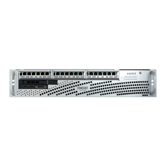
Forcepoint Next Generation Firewall 2U Hardware Guide Model 3201 and 3205 features The figures and tables show the appliance components and features. Front panel This panel has the following parts. Interface modules Indicator lights Power button USB ports Console port (speed 9600 bps) - Page 4 Forcepoint Next Generation Firewall 2U Hardware Guide Back panel This panel has the following parts. AC or DC power supplies IPMI port (usage not recommended) Console port (not used) USB ports VGA port Fixed Ethernet ports...
-
Page 5: Model 3202 Features
Forcepoint Next Generation Firewall 2U Hardware Guide Model 3202 features The figures and tables show the appliance components and features. Front panel This panel has the following parts. Interface module slots Indicator lights Power button USB ports Console port (primary; speed 9600 bps) - Page 6 Forcepoint Next Generation Firewall 2U Hardware Guide Back panel This panel has the following parts. AC or DC power supplies Solid-state drive (SSD) Fan enclosure USB ports IPMI port (usage not recommended) Console port (secondary; speed 9600 bps) VGA port...
-
Page 7: Model 3206 And 3207 Features
Forcepoint Next Generation Firewall 2U Hardware Guide Model 3206 and 3207 features The figures and tables show the appliance components and features. Front panel This panel has the following parts. Interface module slots Indicator lights Power button USB ports Console port (primary; speed 9600 bps) - Page 8 Forcepoint Next Generation Firewall 2U Hardware Guide Back panel This panel has the following parts. AC or DC power supplies Solid-state drive (SSD) Fan enclosure Console port (secondary; speed 9600 bps) IPMI port (usage not recommended) USB ports Fixed Ethernet ports...
-
Page 9: Model 3301 And 3305 Features
Forcepoint Next Generation Firewall 2U Hardware Guide Model 3301 and 3305 features The figures and tables show the appliance components and features. Front panel This panel has the following parts. Interface module slots Indicator lights USB ports Console port (speed 115,200 bps) -
Page 10: Indicator Lights
Forcepoint Next Generation Firewall 2U Hardware Guide Back panel This panel has the following parts. Fan enclosures UID button UID indicator Solid-state drive (SSD) slots (only the upper slot is used) SSD indicators Grounding pin AC or DC power supplies Indicator lights Indicator lights show the status of the appliance and any fixed Ethernet ports. -
Page 11: Ethernet Port Indicators
Forcepoint Next Generation Firewall 2U Hardware Guide Icon Description When flashing, indicates network activity on the onboard Ethernet interface 0. The interface is on the back panel of the appliance. When flashing, indicates SSD activity. Indicates that power is supplied to the system power supply units. This indicator is illuminated when the system is operating normally. -
Page 12: Qsfp+ Port Indicators
Color Explanation Activity/link indicator Amber Link OK, flashes on activity. Link speed indicator Unlit No link. For 3201, 3205, 3206, and 3207 appliances, can indicate a 10 Mbps link. Orange 100 Mbps link. Green 1 Gbps link. QSFP+ port indicators QSFP+ port indicators show the status and speed of the network ports. -
Page 13: Ethernet Port Names For Appliances With Interface Modules
1 is eth1_0. Supported interface modules Forcepoint NGFW appliances support the following types of interface modules. For a list of all available interface modules and compatibility information, see Knowledge Base article 10245. Note Do not remove any stickers from modules —... - Page 14 Forcepoint Next Generation Firewall 2U Hardware Guide Module Identifier Appliance models 8 port gigabit Ethernet RJ45 MOG8 3201, 3202, 3205, 3206, 3207, 3301, 3305 Fiber modules Module Identifier Appliance models 2 port Fiber bypass LC MOE2B 3206, 3207 2 port 10 gigabit Ethernet short reach bypass...
- Page 15 Forcepoint Next Generation Firewall 2U Hardware Guide MO102B module The MO102B module is a two-port 10 gigabit bypass copper module. Number Component Color Description Release lever Activity/link indicator Green Link OK, flashes on activity. Link speed/bypass/disconnect indicator Amber 1 Gbps link, flashes in disconnect mode.
- Page 16 Forcepoint Next Generation Firewall 2U Hardware Guide MOG4B module The MOG4B module is a quad-port gigabit bypass copper module. Number Component Color Description Release lever Activity/link indicator Green Link OK. Link speed/bypass/disconnect indicator Yellow 1 Gbps link, flashes in disconnect mode.
- Page 17 Forcepoint Next Generation Firewall 2U Hardware Guide MOE2B module The MOE2B module is a two-port gigabit bypass fiber module. Number Component Color Description Release lever Activity/link indicator Green Link OK. Link speed/bypass/disconnect indicator Green 1 Gbps link, flashes in bypass mode.
- Page 18 Forcepoint Next Generation Firewall 2U Hardware Guide MO10L2B module The MO10L2B module is a two-port 10 gigabit bypass fiber module. Number Component Color Description Release lever Activity/link indicator Green Link OK. Link speed/bypass/disconnect indicator Blue 10 Gbps link. Green Flashes in bypass mode.
- Page 19 Forcepoint Next Generation Firewall 2U Hardware Guide MO10F2 module The MO10F2 module is a two-port 10 gigabit SFP+ interface module. Number Component Color Description Release lever Activity/link indicator Green Link OK. Link speed indicator Blue 10 Gbps link. MO40F2 module The MO40F2 module is a two-port 40 gigabit QSFP+ interface module.
- Page 20 Forcepoint Next Generation Firewall 2U Hardware Guide Number Component Color Description Release lever Activity/link indicator Green Link OK. Link speed indicator Yellow 1 Gbps link. MO10F4 module The MO10F4 module is a quad-port 10 gigabit SFP+ interface module. Number Component...
-
Page 21: Precautions
The precautions provide safety guidance when working with Forcepoint appliances and electrical equipment. CAUTION Forcepoint appliances cannot be serviced by end users. Never open the appliance covers for any reason. Doing so can lead to serious injury and void the hardware warranty. -
Page 22: Install The Appliance
■ The on-site installer is responsible for installing the appliance. For more information, see the Forcepoint Next Generation Firewall Installation Guide. To prepare for the appliance installation, the SMC administrator must do the following: If the SMC has not yet been installed, install the SMC. - Page 23 Forcepoint Next Generation Firewall 2U Hardware Guide The SMC can manage many NGFW appliances. In the Management Client component of the SMC, create and configure the NGFW Engine element that represents the appliance. In the Management Client component of the SMC, save the initial configuration.
- Page 24 Related concepts General safety precautions on page 21 Install a 3201, 3202, 3205, 3206, or 3207 appliance in a two-post rack Use the rack-mounting brackets to secure the appliance in the rack. Steps Locate the two rack-mounting brackets for the two-post rack installation.
- Page 25 Forcepoint Next Generation Firewall 2U Hardware Guide Install a 3301 or 3305 appliance in a two-post rack Use the rack-mounting brackets to secure the appliance in the rack. Steps Locate the rack-mounting brackets for the two-post rack installation. (Usage optional) Two brackets that attach to the front panel of the appliance.
- Page 26 Use all three screws to attach each rack-mounting bracket to the rack. Using fewer screws might not provide sufficient support and can damage the appliance. Install a 3201, 3202, 3205, 3206, or 3207 appliance in a four-post rack Use the rack-mounting brackets to secure the appliance in the rack.
- Page 27 Forcepoint Next Generation Firewall 2U Hardware Guide Steps Locate the two pairs of brackets, two inner rails that attach to the appliance, and two outer rails that attach to the rack. The rails are marked with "L" for left and "R" for right.
- Page 28 Forcepoint Next Generation Firewall 2U Hardware Guide Attach the second inner rail to the other side of the appliance. Insert the outer rails to the rack. If necessary, push the locking tab on the rail to pull out the outer rails.
- Page 29 Forcepoint Next Generation Firewall 2U Hardware Guide Install a 3301 or 3305 appliance in a four-post rack Use the rack-mounting brackets to secure the appliance in the rack. Use bracket sets of these lengths for installing the appliance in the rack.
- Page 30 Forcepoint Next Generation Firewall 2U Hardware Guide Attach a short bracket to both sides of the appliance using two screws for each bracket. Attach the two longer brackets to the back of the rack with three screws through the holes at the back of each bracket: one screw through the top hole, another through the middle hole, and the third through the bottom hole.
- Page 31 Install the SSD if it is not already installed. The SSD slot is on the front panel of 3201 and 3205 appliances, and on the back panel of 3202, 3206, 3207, 3301, and 3305 appliances. On the 3301 and 3305 appliances, use only the upper slot.
- Page 32 For more information, see the Forcepoint Next Generation Firewall Installation Guide. Network interfaces at both ends of each cable must have identical speed and duplex settings. These settings include the automatic negotiation setting.
- Page 33 Forcepoint Next Generation Firewall 2U Hardware Guide Ethernet port mapping For appliances that have removable interface modules, Ethernet port names are based on the slot and port numbers. The first number in the name represents the slot on the appliance, and the second number represents the port on the slot.
- Page 34 NGFW Engine command line. For sg-bootconfig more information, see Command line tools in the Forcepoint Next Generation Firewall Product Guide. Connect network cables to SFP ports If you installed an SFP interface module on the appliance or the appliance has an integrated SFP port, insert the copper or fiber-optic SFP transceiver into the port, then connect the cables.
-
Page 35: Maintenance
Forcepoint NGFW appliances ship with replaceable components. Turn off the appliance Most Forcepoint NGFW appliance hardware components are not hot-swappable. Turn off the appliance from the NGFW Engine command line. The only hot-swappable components are power supplies, and the 3202, 3206, 3207, 3301, and 3305 appliance fans. - Page 36 Wait until the power indicator light turns red or is unlit, then unplug all power cables from the appliance. Replace the power supply The power supplies are replaceable on most Forcepoint NGFW appliances. If both power supplies are connected to a power source, the power supplies are hot-swappable.
- Page 37 Forcepoint Next Generation Firewall 2U Hardware Guide Replace the appliance fans Replace failed fans to ensure proper cooling of the appliance. There are four front fans and one back fan on 3202, 3206, and 3207 appliances. There are three back fans on 3301 and 3305 appliances.
- Page 38 Replace an SSD with another of the same model. The SSD slot is on the front panel of 3201 and 3205 appliances, and on the back panel of 3202, 3206, 3207, 3301, and 3305 appliances. On the 3301 and 3305 appliances, use only the upper slot.
- Page 39 Forcepoint Next Generation Firewall 2U Hardware Guide Steps Turn off the appliance and disconnect any power cables. Press the release button to release the lever that locks the SSD into position. Pull the lever carefully, then remove the SSD from the slot.
- Page 40 In the network interface configuration options, make sure that the autodetected information is correct and that all interfaces have been detected. If autodetection fails, add network drivers manually. For detailed instructions, see the Forcepoint Next Generation Firewall Installation Guide. If the number of ports in the new module differs from the old module, adjust the mapping of interfaces to interface IDs.
- Page 41 Forcepoint Next Generation Firewall 2U Hardware Guide Note We recommend fastening a grounding strap to your wrist so that it contacts your bare skin and attaching the other end of the strap to the appliance. Steps Turn off the appliance and disconnect any power cables.
- Page 42 © 2020 Forcepoint Forcepoint and the FORCEPOINT logo are trademarks of Forcepoint. All other trademarks used in this document are the property of their respective owners. Published 06 August 2020...
Need help?
Do you have a question about the 3201 and is the answer not in the manual?
Questions and answers