
Related Manuals for Forcepoint 3201


Summary of Contents for Forcepoint 3201
- Page 1 Next Generation Firewall Hardware Guide Models 3201, 3202, 3205, 3206, 3207, 3301, 3305 Revision H...
-
Page 2: Table Of Contents
On the Forcepoint support website, you can find information about a released product, including product documentation, technical articles, and more. You can get additional information and support for your product on the Forcepoint support website at https://support.forcepoint.com. There, you can access product documentation, Knowledge Base articles,... -
Page 3: Model 3201 And 3205 Features
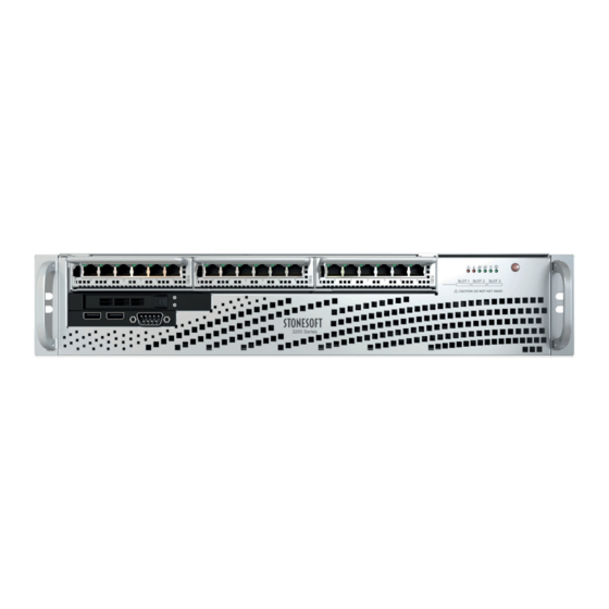
Forcepoint Next Generation Firewall 2U Hardware Guide Model 3201 and 3205 features The figures and tables show the appliance components. Front panel Interface modules Indicator lights Power button USB ports Console port (speed 9600 bps) Solid-state drive (SSD) - Page 4 Forcepoint Next Generation Firewall 2U Hardware Guide Back panel AC or DC power supplies IPMI port (usage not recommended) Console port (not used) USB ports VGA port Fixed Ethernet ports Ethernet port names Ethernet port names are based on the slot and port numbers. The first number in the name represents the slot on the appliance.
-
Page 5: Model 3202, 3206, And 3207 Features
Forcepoint Next Generation Firewall 2U Hardware Guide Model 3202, 3206, and 3207 features The figures and tables show the appliance components. Front panel Interface module slots Indicator lights Power button USB ports Console port (primary; speed 9600 bps) Fan enclosure plate... - Page 6 Forcepoint Next Generation Firewall 2U Hardware Guide 3202 appliance back panel AC or DC power supplies Solid-state drive (SSD) Fan enclosure USB ports IPMI port (usage not recommended) Console port (secondary; speed 9600 bps) VGA port Fixed Ethernet ports...
- Page 7 Forcepoint Next Generation Firewall 2U Hardware Guide 3206 and 3207 appliance back panel AC or DC power supplies Solid-state drive (SSD) Fan enclosure Console port (secondary; speed 9600 bps) IPMI port (usage not recommended) USB ports Fixed Ethernet ports VGA port Ethernet port names Ethernet port names are based on the slot and port numbers.
-
Page 8: Model 3301 And 3305 Features
Forcepoint Next Generation Firewall 2U Hardware Guide Model 3301 and 3305 features The figures and tables show the appliance components. Front panel Interface module slots Indicator lights USB ports Console port (speed 115,200 bps) VGA port QSFP+ port (3305 appliances only) Note: You can only use a short-range transceiver in this port. - Page 9 Forcepoint Next Generation Firewall 2U Hardware Guide Back panel Fan enclosures UID button UID indicator Solid-state drive (SSD) slots (only the upper slot is used) SSD indicators Grounding pin AC or DC power supplies Ethernet port names Ethernet port names are based on the slot and port numbers. The first number in the name represents the slot on the appliance.
-
Page 10: Fixed Port Indicators
Activity indicator Amber Link OK, flashes on activity. Link indicator Unlit No link. Note: For 3201, 3205, 3206, or 3207 appliances, an unlit link indicator can indicate that the speed is 10 Mbps. Orange 100 Mbps link. Green 1 Gbps link. -
Page 11: Front Panel Indicator Lights
Front panel indicator lights The front panel indicators vary depending on the appliance model. The SSD indicators are the same for all 2U appliances. Front panel indicators on models 3201, 3202, 3205, 3206, 3207 Indicates that a power supply cable is detached. -
Page 12: Supported Interface Modules
An SSD is in the bay. Disk indicator Unlit This indicator is not used. Supported interface modules Forcepoint NGFW appliances support copper, fiber, and small form-factor pluggable (SFP) modules. Note: Do not remove any stickers from modules — they contain important information. - Page 13 Forcepoint Next Generation Firewall 2U Hardware Guide For a list of all available interface modules and compatibility information, see Knowledge Base article 10245. Table 1: Copper modules Module Identifier Appliance models 2 port 10 gigabit Ethernet RJ45 module MO102 3201, 3202, 3205, 3206,...
- Page 14 Forcepoint Next Generation Firewall 2U Hardware Guide Copper interface modules Forcepoint NGFW appliances support these copper interface modules. MO102 module The MO102 module is a two-port 10 gigabit copper interface module. Number Component Color Description Release lever Activity/link indicator Green Link OK, flashes on activity.
- Page 15 Forcepoint Next Generation Firewall 2U Hardware Guide MOG4 module The MOG4 module is a quad-port gigabit interface module. Number Component Color Description Release lever Activity/link indicator Green Link OK. Link speed indicator Green 1 Gbps link. Amber 100 Mbps link.
- Page 16 1 Gbps link. Green 100 Mbps link. Unlit 10 Mbps link. Release lever Fiber interface modules Forcepoint NGFW appliances support these fiber interface modules. MOE2B module The MOE2B module is a two-port gigabit bypass fiber module. Number Component Color Description...
- Page 17 Forcepoint Next Generation Firewall 2U Hardware Guide Number Component Color Description Activity/link indicator Green Link OK. Link speed/bypass/disconnect indicator Green 1 Gbps link, flashes in bypass mode. Yellow Flashes in disconnect mode. MO10S2B module The MO10S2B module is a two-port 10 gigabit bypass fiber module.
- Page 18 Green 1 Gbps link, flashes in bypass mode. Yellow Flashes in disconnect mode. SFP interface modules Forcepoint NGFW appliances support these SFP interface modules. MO10F2 module The MO10F2 module is a two-port 10 gigabit SFP+ interface module. Number Component Color...
- Page 19 Forcepoint Next Generation Firewall 2U Hardware Guide MO40F2 module The MO40F2 module is a two-port 40 gigabit QSFP+ interface module. Number Component Color Description Release lever Activity/link/link speed indicator Green 40 Gbps link (other speeds not supported), flashes on activity.
- Page 20 Forcepoint Next Generation Firewall 2U Hardware Guide MO10F4 module The MO10F4 module is a quad-port 10 gigabit SFP+ interface module. Number Component Color Description Release lever Activity/link indicator Green Link OK. Link speed indicator Blue 10 Gbps link. MOE10F4 module The MOE10F4 module is a quad-port 10 gigabit SFP+ interface module.
-
Page 21: Precautions
Forcepoint Next Generation Firewall 2U Hardware Guide Precautions The precautions provide safety guidance when working with Forcepoint appliances and electrical equipment. Safety precautions Read the safety information and follow the procedures whenever you are working with electronic equipment. CAUTION: Forcepoint appliances cannot be serviced by end users. Never open the appliance covers for any reason. - Page 22 To avoid injury, do not open the enclosures of power supplies or solid-state drives (SSDs). Power supply safety precautions Depending on the type of power supply that your Forcepoint NGFW appliance uses, different safety precautions and installation guidelines apply. Note: If the appliance has two power supplies, we recommend that you use both power supplies for redundancy.
-
Page 23: Install The Appliance
Forcepoint Next Generation Firewall 2U Hardware Guide Install the appliance Prepare and install the appliance in your network. Before you begin • Install a Security Management Center (SMC) on a separate server. • Configure the NGFW Engine element (Firewall, IPS, or Layer 2 Firewall) in the Management Client, and save the initial configuration. - Page 24 Forcepoint Next Generation Firewall 2U Hardware Guide Install a 3201, 3202, 3205, 3206, or 3207 appliance in a two-post rack Use the rack-mounting brackets to secure the appliance in the rack. Steps Locate the two rack-mounting brackets for the two-post rack installation.
- Page 25 Forcepoint Next Generation Firewall 2U Hardware Guide Install a 3301 or 3305 appliance in a two-post rack Use the rack-mounting brackets to secure the appliance in the rack. Steps Locate the rack-mounting brackets for the two-post rack installation. (Usage optional) Two brackets that attach to the front panel of the appliance.
- Page 26 CAUTION: Use all three screws to attach each rack-mounting bracket to the rack. Using fewer screws might not provide sufficient support and can damage the appliance. Install a 3201, 3202, 3205, 3206, or 3207 appliance in a four-post rack Use the rack-mounting rails to secure the appliance in the rack.
- Page 27 Forcepoint Next Generation Firewall 2U Hardware Guide Steps Locate the two pairs of brackets, two inner rails that attach to the appliance, and two outer rails that attach to the rack. The rails are marked with "L" for left and "R" for right.
- Page 28 Forcepoint Next Generation Firewall 2U Hardware Guide Align the holes against the corresponding buttons. When all are aligned, push the holes toward the corresponding buttons. Front of appliance Top of appliance Screws Secure the rail to the appliance with a screw.
- Page 29 Forcepoint Next Generation Firewall 2U Hardware Guide Line up the rear of the inner rails with the front of the extended outer rails. Top of appliance Front of appliance Slide the inner rails into the outer rails, keeping the pressure even on both sides.
- Page 30 Forcepoint Next Generation Firewall 2U Hardware Guide Steps Locate the two pairs of brackets in the delivery package: two short brackets that attach to the appliance and two longer brackets that attach to the rack. Short bracket (attaches to the appliance) Longer bracket (attaches to the rack) Attach a short bracket to both sides of the appliance using two screws for each bracket.
- Page 31 Install the SSD Install the SSD if it is not already installed. The SSD is on the front panel of 3201 and 3205 appliances, and on the back panel of 3202, 3206, 3207, 3301, and 3305 appliances. There are two SSD slots on the back panel of 3301 and 3305 appliances. Use only the upper slot.
- Page 32 Forcepoint Next Generation Firewall 2U Hardware Guide Install an interface module If needed, install any interface modules. Before you begin • Read the safety precautions. • Make sure any interface modules you install are the correct type for your appliance.
- Page 33 Use at least CAT5e-rated cables for gigabit networks. Always use standard cabling methods. Use crossover cables to connect the appliance to hosts and straight cables to connect the appliance to switches or hubs. For more information, see the Forcepoint Next Generation Firewall Installation Guide.
- Page 34 Forcepoint Next Generation Firewall 2U Hardware Guide Figure 1: Original interface ID mapping If you replace the four-port module installed in slot 1 with a two-port module, eth1_2 with ID 10 and eth1_3 with ID 11 are removed. Figure 2: Changed interface ID mapping Connect network and management cables Connect the appliance to your networks.
- Page 35 To use the serial console after the initial configuration on these appliances, use the command sg-bootconfig on the engine command line. For more information, see Command line tools in the Forcepoint Next Generation Firewall Product Guide for more information.
-
Page 36: Maintenance
Forcepoint NGFW appliances ship with replaceable components. Turn off the appliance Most Forcepoint NGFW 2U appliance hardware components are not hot-swappable. The only hot-swappable components are power supplies, and the 3202, 3206, 3207, 3301, and 3305 appliance fans. Turn off the appliance and disconnect power before replacing other hardware components. - Page 37 Forcepoint Next Generation Firewall 2U Hardware Guide Replace the power supply The appliances support both AC and DC power supplies. In the event of a failure, replace the power supply. CAUTION: Do not open the casing of a power supply module. Power supply modules can only be repaired by a qualified technician from the manufacturer.
- Page 38 CAUTION: Do not use excessive force when reinserting fans. Doing so can damage or misalign the power connector. Reattach the fan enclosure plate. Replace the back fan on 3201, 3206, and 3207 appliances Access the back fan from the fan enclosure on the back panel.
- Page 39 Replace the SSD Replace an SSD with another of the same model. The SSD is on the front panel of 3201 and 3205 appliances, and on the back panel of 3202, 3206, 3207, 3301, and 3305 appliances. There are two SSD slots on the back panel of 3301 and 3305 appliances. Use only the upper slot.
- Page 40 In the network interface configuration options, make sure that the autodetected information is correct and that all interfaces have been detected. If autodetection fails, add network drivers manually. For detailed instructions, see the Forcepoint Next Generation Firewall Installation Guide. If the number of ports in the new module differs from the old module, adjust the mapping of interfaces to interface IDs.
- Page 41 Forcepoint Next Generation Firewall 2U Hardware Guide Steps Turn off the appliance and disconnect any power cables. Unplug all power cables from the system or the wall outlets. Disconnect the cable from the SFP transceiver. Pull down the latch on the transceiver and carefully pull the SFP transceiver out of the port slot.
- Page 42 © 2018 Forcepoint Forcepoint and the FORCEPOINT logo are trademarks of Forcepoint. Raytheon is a registered trademark of Raytheon Company. All other trademarks used in this document are the property of their respective owners.
Need help?
Do you have a question about the 3201 and is the answer not in the manual?
Questions and answers