Table of Contents
Advertisement
Quick Links
Download this manual
See also:
Hardware Manual
Advertisement
Table of Contents

Related Manuals for Forcepoint 3201


Summary of Contents for Forcepoint 3201
- Page 1 Stonesoft Next Generation Firewall Hardware Guide Models 3201, 3202, 3205, 3206, 3207, 3301, 3305 Revision F...
-
Page 2: Table Of Contents
Table of contents 1 Appliance features............................... 3 Model 3201 and 3205 features........................3 Model 3202, 3206, and 3207 features......................4 Model 3301 and 3305 features........................6 Indicator lights..............................7 Interface modules............................9 2 Precautions................................. 15 Safety precautions............................15 Electrical safety precautions........................15 Power supply safety precautions.........................16... -
Page 3: Appliance Features
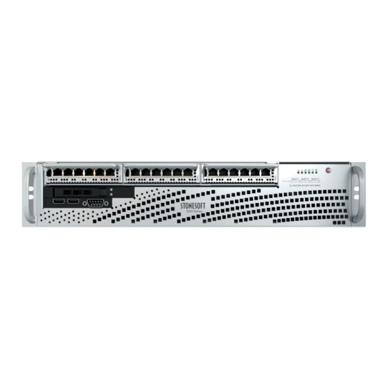
Appliance features Familiarize yourself with the front panel, back panel, and indicator lights. Model 3201 and 3205 features The figures and tables show the appliance components. Front panel Interface modules Indicator lights Power button USB ports Console port (speed 9600 bps) -
Page 4: Model 3202, 3206, And 3207 Features
Ethernet port names Ethernet port names are based on the slot and port numbers. The first number in the name represents the slot on the appliance. The second number represents the port on the slot. Example: eth2_0 is located on port 0 of slot 2. Component Slot number Slot location... - Page 5 3202 appliance back panel AC or DC power supplies Solid-state drive (SSD) Fan enclosure USB ports IPMI port (usage not recommended) Console port (secondary; speed 9600 bps) VGA port Fixed Ethernet ports 3206 and 3207 appliance back panel AC or DC power supplies Solid-state drive (SSD) Fan enclosure Console port (secondary;...
-
Page 6: Model 3301 And 3305 Features
Component Slot number Slot location Port numbers Interface modules 1–3 Front panel The port numbers start from 0 and increase from The slot numbers for the left to right. interface modules start from 1 and increase from Example: The port farthest left to right. -
Page 7: Indicator Lights
The front panel indicators vary depending on the appliance model. The SSD indicators are the same for all 2U appliances. Front panel indicators on Stonesoft NGFW 3201, 3202, 3205, 3206, 3207 appliances Indicates that a power supply cable is detached. - Page 8 When flashing, indicates a fan failure. When continuously on, indicates an overheat condition, which can be caused by cables obstructing the airflow in the system or the ambient room temperature being too warm. When flashing, indicates network activity on the onboard Ethernet interface 1. The interface is on the back panel of the appliance.
-
Page 9: Interface Modules
Activity indicator Amber Link OK, blinks on activity. Link indicator Unlit No link. Note: For 3201, 3205, 3206, or 3207 appliances, this could indicate that the speed is 10 Mbps. Orange 100 Mbps link. Green 1 Gbps link. Interface modules Stonesoft NGFW appliances support four types of modules. - Page 10 Copper interface modules Stonesoft NGFW appliances support these copper interface modules. Dual-port modules • MOD-EM1-10G-2 (10G2) — 10 gigabit interface module • MOD-10G-2-B (10G2B) — 10 gigabit bypass module Number Component Color Description Release lever Activity/link indicator Green Link OK, blinks on activity. MOD-EM1-10G-2 (10G2) —...
- Page 11 Number Component Color Description MOD-GE-4 (GE4) — Link speed indicator Green 1 Gbps link. Amber 100 Mbps link. MOD-GE-4-B (GE4B) — Link speed/bypass/ Yellow 1 Gbps link, blinks in disconnect indicator disconnect mode. Green 100 Mbps link, blinks in bypass mode. Unlit 10 Mbps link.
- Page 12 Number Component Color Description 3, 6 Link speed indicator Yellow 1 Gbps link. Green 100 Mbps link. Unlit 10 Mbps link. Release lever Fiber interface modules Stonesoft NGFW appliances support these fiber interface modules. Dual-port bypass modules • MOD-GE-SX-2-B (GESX2B) — Gigabit bypass module (not 3301 or 3305 appliances) •...
- Page 13 Number Component Color Description Release lever Activity/link indicator Green Link OK. Link speed/bypass/disconnect indicator Green 1 Gbps link, blinks in bypass mode. Yellow Blinks in disconnect mode. SFP interface modules Stonesoft NGFW appliances support these SFP interface modules. Dual-port interface modules •...
- Page 14 Number Component Color Description Release lever Activity/link/link speed indicator Green 40 Gbps link (other speeds not supported), blinks on activity. Quad-port interface modules • MOD-GE-SFP-4 (GE4SFP) — Gigabit interface module (SFP) • MOD-10G-SFP-4 (10GSFP4) — 10 gigabit interface module (SFP+) (not 3207, 3301, and 3305 appliances) •...
-
Page 15: Precautions
Precautions The precautions provide safety guidance when working with Forcepoint appliances and electrical equipment. Safety precautions Read the safety information and follow the procedures whenever you are working with electronic equipment. CAUTION: Forcepoint appliances cannot be serviced by end users. Never open the appliance covers for any reason. -
Page 16: Power Supply Safety Precautions
• To avoid injury, do not open the enclosures of power supplies or solid-state drives (SSDs). Power supply safety precautions Depending on the type of power supply that your Stonesoft NGFW appliance uses, different safety precautions and installation guidelines apply. AC power supplies The appliance has 1–2 connectors for an AC power supply. -
Page 17: Install The Appliance
Install the SSD Install the SSD if it is not already installed. The SSD is on the front panel of 3201 and 3205 appliances, and on the back panel of 3202, 3206, 3207, 3301, and 3305 appliances. There are two SSD slots on the back panel of 3301 and 3305 appliances. Use only the upper slot. -
Page 18: Rack-Mount The Appliance
To maintain proper cooling, always keep the front door of the rack and all panels and components on the appliances closed when not servicing. Install a 3201, 3202, 3205, 3206, or 3207 appliance in a two-post rack Use the rack-mounting brackets to secure the appliance in the rack. - Page 19 Locate the three pairs of supports on the side of the appliance and the corresponding holes on the brackets. Align the holes against the two supports toward the rear of the appliance and push the bracket under the supports. The brackets are marked with "L" for left and "R" for right. Secure the bracket to the appliance by inserting a screw through the hole at the end of the bracket.
- Page 20 CAUTION: Use all three screws to attach each rack-mounting bracket to the rack. Using fewer screws might not provide sufficient support and can damage the appliance. Install a 3201, 3202, 3205, 3206, or 3207 appliance in a four-post rack Use the rack-mounting rails to secure the appliance in the rack.
- Page 21 Align the holes against the corresponding buttons. When all are aligned, push the holes toward the corresponding buttons. Front of appliance Top of appliance Screws Secure the rail to the appliance with a screw. Attach the second inner rail to the other side of the appliance. Insert the outer rails to the rack.
- Page 22 Top of appliance Front of appliance Slide the inner rails into the outer rails, keeping the pressure even on both sides. Tip: You might have to press the locking tabs when inserting the rails. When the appliance is pushed completely into the rack, the locking tabs click as the rails lock. Install a 3301 or 3305 appliance in a four-post rack Use the rack-mounting brackets to secure the appliance in the rack.
- Page 23 Short bracket (attaches to the appliance) Longer bracket (attaches to the rack) Attach a short bracket to both sides of the appliance using two screws for each bracket. Attach the two longer brackets to the back of the rack with three screws through the holes at the back of each bracket: one screw through the top hole, another through the middle hole, and the third through the bottom hole.
-
Page 24: Connect The Cables
Note: These screws support the appliance when it is inserted into the rack. The number and position of the screws depends on the depth of the rack. Line up the screws that you have attached to the appliance with the groove in the brackets attached to the rack. - Page 25 During the initial configuration of the appliance, the Ethernet ports are mapped to the interface IDs that you defined in the Management Client. The NGFW Configuration Wizard displays the mapping between the interface IDs and port names. In the command line version of the NGFW Configuration Wizard, Interface IDs appear in the column and port names appear in the Name...
- Page 26 Connect network cables to SFP ports If you installed an SFP interface module on the appliance, insert the copper or fiber-optic SFP transceiver into the module and connect the cables. Insert the SFP transceiver in the port slot until you feel the connector on the transceiver snap into place. Note: Make sure that the latch on the SFP transceiver is up when you insert the SFP transceiver in the port slot.
-
Page 27: Maintenance
Maintenance Stonesoft NGFW appliances ship with several replaceable components. Turn off the appliance Most Stonesoft NGFW 2U appliance hardware components are not hot-swappable. The only hot-swappable components are the 3202, 3206, 3207, 3301, and 3305 appliance fans. Turn off the appliance and disconnect power before replacing other hardware components. -
Page 28: Replace Appliance Fans
Replace appliance fans There are four front fans and one back fan on 3202, 3206, or 3207 appliances. There are three back fans on 3301 and 3305 appliances. You can change the fans without turning off the appliance. We recommend that you replace all appliance fans at the same time. -
Page 29: Replace The Ssd
Replace the SSD Replace an SSD with another of the same model. The SSD is on the front panel of 3201 and 3205 appliances, and on the back panel of 3202, 3206, 3207, 3301, and 3305 appliances. There are two SSD slots on the back panel of 3301 and 3305 appliances. Use only the upper slot. -
Page 30: Remove Sfp Transceivers
Remove SFP transceivers Remove or replace an SFP transceiver. CAUTION: Invisible laser radiation is emitted from the end of a fiber-optic cable and from the fiber port. Do not stare into the beam and avoid direct exposure to the beam. Note: We recommend fastening a grounding strap to your wrist so that it contacts your bare skin and attaching the other end of the strap to the appliance. -
Page 31: Find Product Documentation
On the Forcepoint support website, you can find information about a released product, including product documentation, technical articles, and more. You can get additional information and support for your product on the Forcepoint support website at https:// support.forcepoint.com. There, you can access product documentation, Knowledge Base articles, downloads, cases, and contact information.
Need help?
Do you have a question about the 3201 and is the answer not in the manual?
Questions and answers