
Related Manuals for Forcepoint 330 Series


Summary of Contents for Forcepoint 330 Series
- Page 1 Next Generation Firewall 330 Series Hardware Guide Models 330, 331, 335, 335W Revision B...
-
Page 2: Table Of Contents
On the Forcepoint support website, you can find information about a released product, including product documentation, technical articles, and more. You can get additional information and support for your product on the Forcepoint support website at https://support.forcepoint.com. There, you can access product documentation, Knowledge Base articles,... -
Page 3: Model 330 And 331 Features
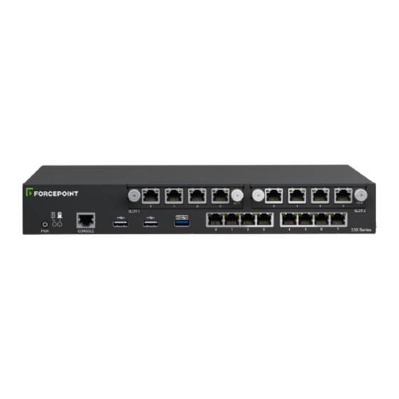
Forcepoint Next Generation Firewall Hardware Guide | Models 330, 331, 335, 335W Model 330 and 331 features The figures and tables show the appliance components and features. Front panel This panel has the following parts. Power button. The indicator on the button shows if the power is on. -
Page 4: Model 335 And 335W Features
Forcepoint Next Generation Firewall Hardware Guide | Models 330, 331, 335, 335W Model 335 and 335W features The figures and tables show the appliance components and features. Front panel This panel has the following parts. Interface module slot 1 Interface module slot 2 Power button. -
Page 5: Indicator Lights
Forcepoint Next Generation Firewall Hardware Guide | Models 330, 331, 335, 335W Back panel This panel has the following parts. (Model 335W only) Antenna connectors CFast Card 19V DC power connectors A and B from left to right CAUTION: The power connectors are intended to provide power to the Forcepoint appliance only. -
Page 6: Ethernet Port Indicators
Forcepoint Next Generation Firewall Hardware Guide | Models 330, 331, 335, 335W Icon Indicator Color Description Wireless status Green The wireless interface is configured as a wireless access point and is active. (Model 335W only) Ethernet port indicators Ethernet port indicators show the status and speed of the network ports. -
Page 7: Supported Interface Modules
Forcepoint Next Generation Firewall Hardware Guide | Models 330, 331, 335, 335W Supported interface modules Forcepoint NGFW appliances support the following types of interface modules. For a list of all available interface modules and compatibility information, see Knowledge Base article 10245. - Page 8 Forcepoint Next Generation Firewall Hardware Guide | Models 330, 331, 335, 335W MMGE4 module The MMGE4 module is a quad-port gigabit interface module. Number Component Color Description Activity/link indicator Green Link OK, flashes on activity. Link speed indicator Green 1 Gbps link.
-
Page 9: Precautions
Thumbscrews Precautions The precautions provide safety guidance when working with Forcepoint appliances and electrical equipment. CAUTION: Forcepoint appliances cannot be serviced by end users. Never open the appliance covers for any reason. Doing so can lead to serious injury and void the hardware warranty. -
Page 10: Install The Appliance
Forcepoint Next Generation Firewall Hardware Guide | Models 330, 331, 335, 335W Operating precautions Follow these precautions when operating the appliance. • Do not open the power adapter casing. Only the manufacturer's qualified technician can access and service power adapters. - Page 11 Forcepoint Next Generation Firewall Hardware Guide | Models 330, 331, 335, 335W Important: Do not install the SMC on the NGFW appliance. The SMC can manage many NGFW appliances. In the Management Client component of the SMC, create and configure the NGFW Engine element that represents the appliance.
- Page 12 Forcepoint Next Generation Firewall Hardware Guide | Models 330, 331, 335, 335W Install the appliance in a two or four-post rack Use the rack-mounting brackets to secure the appliance in the rack. The bracket and screws are not included by default. You can order them separately. When you install the appliance in a four-post rack, only two posts are used.
- Page 13 Forcepoint Next Generation Firewall Hardware Guide | Models 330, 331, 335, 335W Install an interface module If needed, install any interface modules. Before you begin Read the safety precautions and make sure any interface modules you install are the correct type for your appliance.
- Page 14 Forcepoint Next Generation Firewall Hardware Guide | Models 330, 331, 335, 335W The settings for inline interfaces must be identical for all four interfaces. The pair on the appliance and the interfaces on the two devices connecting to the appliance must have the same speed and duplex settings configured.
- Page 15 Forcepoint Next Generation Firewall Hardware Guide | Models 330, 331, 335, 335W Steps Locate the antennas included in the appliance delivery. Attach the antennas to the connectors on the back panel of the appliance. Tighten the knurled nuts at the base of the antennas to secure them firmly to the appliance.
-
Page 16: Maintenance
Some Forcepoint NGFW appliances ship with replaceable components. Turn off the appliance Most Forcepoint NGFW appliance hardware components are not hot-swappable. Turn off the appliance from the NGFW Engine command line. Turn off the appliance and disconnect power before replacing the CFast card or interface modules. - Page 17 Forcepoint Next Generation Firewall Hardware Guide | Models 330, 331, 335, 335W Wait until the power indicator light turns red or is unlit, then unplug all power cables from the appliance. Replace the CFast card Replace the CFast card with another card that you received from Forcepoint.
- Page 18 In the network interface configuration options, make sure that the autodetected information is correct and that all interfaces have been detected. If autodetection fails, add network drivers manually. For detailed instructions, see the Forcepoint Next Generation Firewall Installation Guide. If the number of ports in the new module differs from the old module, adjust the mapping of interfaces to interface IDs.
-
Page 19: Compliance Information
If needed, insert a replacement SFP transceiver in the slot. Compliance information Forcepoint NGFW appliances that have wireless support are in compliance with certain EU directives and FCC standards for wireless devices intended for home and office use. This information is valid for all dual band products (2.4 GHz, IEEE 802.11b/g/n, and 5 GHz, IEEE 802.11a/n/ac). - Page 20 Forcepoint Next Generation Firewall Hardware Guide | Models 330, 331, 335, 335W EU Directives This appliance is in compliance with: • EMC directive 2014/30/EU • LVD directive 2014/35/EU • RED directive 2014/53/EU The frequencies and maximum transmitted power in the EU are: •...
- Page 21 Forcepoint Next Generation Firewall Hardware Guide | Models 330, 331, 335, 335W this device must accept any interference, including interference that may cause undesired operation of the device. 1 Le présent appareil est conforme aux CNR d'Industrie Canada applicables aux appareils radio exempts de licence.
- Page 22 Forcepoint Next Generation Firewall Hardware Guide | Models 330, 331, 335, 335W for devices with detachable antenna(s), the maximum antenna gain permitted for devices in the band 5725-5850 MHz shall be such that the equipment still complies with the e.i.r.p. limits as appropriate;...
- Page 23 © 2019 Forcepoint Forcepoint and the FORCEPOINT logo are trademarks of Forcepoint. All other trademarks used in this document are the property of their respective owners.
Need help?
Do you have a question about the 330 Series and is the answer not in the manual?
Questions and answers