Table of Contents
Advertisement
Advertisement
Table of Contents

Related Manuals for King gates Intro 230


Summary of Contents for King gates Intro 230
- Page 1 Intro Motorgear for swing gates INSTRUCTION MANUAL MADE IN ITALY...
- Page 2 1 - TYPICAL AUTOMATION 1- Operators 6-Key-switch 2- Flashing warning light 7-Electronic control unit 3- Antenna 8-Warning sign 4- Photocell 9-Stop locks 5- Small columm...
-
Page 3: Technical Data
2 - TECHNICAL DATA Intro 230 Intro 24 Power supply 230 V 230 V Motor power supply 230 V 24 V Motor power 200 W 50 W Consuption 1,3 A 2,5 A Capacitor 12,5 nF Working temperature -20 ÷ +55 °C -20 ÷... -
Page 4: Typical Connection And Cable Section
4 - TYPICAL CONNECTION AND CABLE SECTION STAR 2 x 1.5 mm (Intro 24) 3 x 1.5 mm (Intro 230) 2 x 0.75 mm 4 x 0.75 mm 2 x 0.75 mm 230V 3 x 1.5 mm INTRO 230 CONNECTION... -
Page 5: Installation
5 - INSTALLATION -The installation and testing operations must be performed solely by qualified personnel in order to guarantee the proper and safe operation of the automatic gate. -Antoniolli Mario & C. s a s, declines any responsibility for damage caused by incorrect installations due to incompetence and/or negligence. -
Page 6: Box Installation Procedure
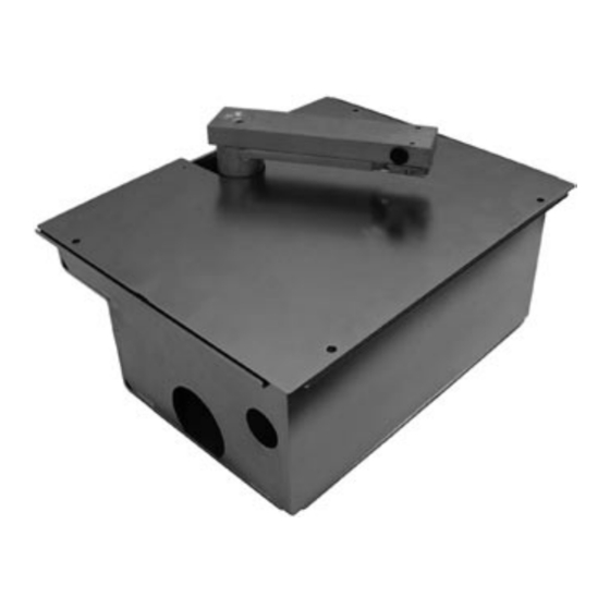
5.2 BOX INSTALLATION PROCEDURE Dig a hole big enough to hold the box containing the operator. Insert the tubes for water drainage in the prepared holes (A) Insert the sheath for laying the power cables and limit switch (B). Note: while positioning the box, keep in mind the minimum distance there must be between the pillar and the centre of rotation of the gate hinge. - Page 7 6 OPERATOR AND LEVERS 6.1 ASSEMBLING Place the operator in the box and fasten it with the nuts provided. Insert the ball in the pin located on the box and fit the gate anchorage lever (L1).
-
Page 8: Fastening The Operator Lever To The Gate
Insert the lever (L3) onto the motor shaft Fit the connecting lever (L2) 6.2 FASTENING THE OPERATOR LEVER TO THE GATE Insert the cover and fasten it with the screws provided Position the gate wing and the lever (L1) so that they are perfectly aligned and fasten them by welding or similar... -
Page 9: Emergency Release Procedure
6.3 EMERGENCY RELEASE PROCEDURE -Insert the key (C) provided into the appropriate hole (D), on the lever L1. -Turn the key clockwise by about 45°... -
Page 10: Safety Precautions
7 SAFETY PRECAUTIONS These warnings are an essential, integral part of the product and must be given to the user. They provide important indications on the installation, use and maintenance and must be read carefully. This form must be preserved and passed on to subsequent users of the system. The incorrect installation or improper use of the product may be dangerous. -
Page 11: Spare Parts
8 SPARE PARTS PART NUMBER MOTOR VERSION CODE Intro 230 / Intro 24 RI01LC Intro 230 / Intro 24 RI02LM Intro 230 RI230MO Intro 24 RI24MO Intro 230 RI01MR Intro 24 RI02MR Intro 230 / Intro 24 RI01CA... - Page 12 TELEPHONE NUMBER: CONTACT PERSON: PRODUCER REFERENCE KING gates - Brand of Antoniolli Mario & C. s a s Via A. Malignani, 42 - 33077 Sacile (PN) ITALY Tel. +39 0434 737082 - Fax +39 0434 783382 e-mail: info@king-gates.com web: www.king-gates.com...
Need help?
Do you have a question about the Intro 230 and is the answer not in the manual?
Questions and answers