
Related Manuals for King gates jet


Summary of Contents for King gates jet
- Page 1 Automatika varstomiems vartams Motor gear for swing gates MONTAVIMO INSTRUKCIJOS INSTRUCTION MANUAL PAGAMINTA ITALIJOJE...
-
Page 2: Techniniai Duomenys
Prieš pradedant montuoti automatiką, atidžiai perskaitykite visus šios knygelės skyrius. Jeigu nesate tikri dėl kažkurių veiksmų, nedelsdami nutraukite automatikos instaliavimą ir susisiekite su UAB “Idomus” įmonės darbuotoju arba KING-gates klientų aptarnavimo skyriumi. -Svarbu: pasilikite šią montavimo instrukciją automatikos priežiūrai ir likvidavimui. JET ASORTIMENTAS 1B - TECHNINIAI DUOMENYS Kodas... - Page 3 2 - PAJUNGIMO SCHEMA 2A - PAJUNGIMO SCHEMA A - Pavara B - Valdymo blokas C - Švyturėlis D - Fotoelementai E - Stulpeliniai fotoelementai F - Raktinis jungiklis 2B - LAIDŲ PAJUNGIMO SCHEMA RG58 (dist max 5m) 0,5mm2 (dist max 50m) 0,5mm2 (dist max 20m) 0,5mm2 (dist max 50m) 0,5mm2 (dist max 20m)
- Page 4 2C - laikiklis laikiklis 130mm 130mm 40mm 60mm 60mm laikiklis 130mm...
- Page 5 3 - LAIKIKLIŲ MONTAVIMO SCHEMA 3A - KAIP NAUDOTIS SCHEMA Pamatuokite "E" ir brėžkite horizontalią liniją. (pav.3.3, 3.4, 3.5, 3.6). Pasirinkite tašką nubrėžtoje linijoje, priklausomai nuo pasirinkto atidarymo kampo. Brėžkite vertikalią liniją nuo to paties taško, kad nustatytumėt A reikšmę. Įsitikinkite, kad A reikšmė...
- Page 6 3B - MONTAVIMO SCHEMA: MECHANINIAI RIBOTUVAI ATIDARYMUI MECHANINIAI RIBOTUVAI ATIDARYMUI 90° 100° 110° A (mm) Pav. 3.3...
- Page 7 3C - MONTAVIMO SCHEMA: MECHANINIAI RIBOTUVAI UŽDARYMUI MECHANINIAI RIBOTUVAI UŽDARYMUI 90° 100° 110° A (mm) Pav. 3.4...
- Page 8 3D - MONTAVIMO SCHEMA: MECHANINIAI RIBOTUVAI ATIDARYMUI IR UŽDARYMUI MECHANINIAI MECHANINIAI RIBOTUVAI RIBOTUVAI ATIDARYMUI UŽDARYMUI 90° 100° A (mm) Pav. 3.5...
- Page 9 3E - MONTAVIMO SCHEMA: BE MECHANINIŲ RIBOTUVŲ BE MECHANINIŲ RIBOTUVŲ 90° 100° 110° A (mm) Pav. 3.4...
- Page 10 4 - MONTAVIMAS 4A - ĮVADAS Prieš pradėdami šios sistemos montavimo darbus, perskaitykite šią instrukciją.Naudokite šią įrangą tik pagal tą paskirtį, kuri yra nurodyta šioje instrukcijoje. Montuotojas, montuojantis šį gaminį, vartotojui turi pateikti visą informaciją apie šio gaminio funkcijas ir vartotojo instrukciją. 4B - LAIKIKLIŲ...
-
Page 11: Rankinis Valdymas
5 - RANKINIS VALDYMAS 5A - ĮVADAS ! Pirmiausia atjunkite pavaros maitinimą Rankinis valdymas skirtas naudoti tada, kai nutrūksta elektros tiekimas. 5B - ATPALAIDAVIMAS INSTRUKCIJA (pav. 4). - Įstatykite raktą į spyną ir pasukite 90° pagal laikrodžio rodyklę. - Pastatykite pavarą reikiamoje padėtyje. 5C - ATSATYMAS INSTRUKCIJA (Pav.5). - Page 12 Ši procedūra gali būti atliekama tik įgaliotų darbuotojų. Išardykite jungtį atsukdami varžtą "A" (pav.6) DĖMESIO: elektros jungtis pavaroje yra įdiegta. 6A - JUNGTIS PRIE MAITINIMO 1 Fazė 1 JET 230 F 2 Fazė 2 3 Bendra Įžeminimas JET 24 1 M+...
- Page 13 7 - MECHANINIAI RIBOTUVAI 7A - ĮVADAS Mechaniniai ribotuvai reikalingi, kad automatika sustabdytu vartus reikiamoje pozicijoje. 7B - REGULIAVIMO INSTRUKCIJA INSTRUKCIJA (pav.7): - Paruoškite pavarą rankiniam valdymui (pav.4). - Atsukite mechaninio ribotuvo varžtą (B ar D). - Pasukite vartus norimoje atidarymo/uždarymo pozicijoje. - Pastatykite mechaninį...
-
Page 14: General Description
1 - GENERAL DESCRIPTION 1A - WARNINGS Unfulfilment of the below listed instructions will release the KING gates srl, from any responsibility for damage caused to people or things. -Do not modify the product in any part. -To optimize the functioning of the automation use KING gates accessories only. -
Page 15: Typical System
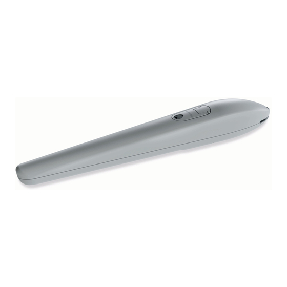
2 - TYPICAL SYSTEM 2A - TYPICAL SYSTEM A - Gear-motor B - Control unit C - Flashing-light with antenna D - Photocells (while closing) E - Photocells (while opening) F - Key selector G - Warning sign H - Stop locks 2B - TYPICAL CONNECTION AND CABLE SECTION RG58 (dist max 5m) 0,5mm2 (dist max 50m) - Page 16 2C - DIMENSIONS Front Rear braket braket 130mm 130mm 40mm 60mm Rear vertical 60mm braket 130mm...
- Page 17 3 - BRACKETS INSTALLATION SCHEME 3A - HOW TO USE THE SCHEME Measure "E" and draw a horizontal line in the scheme (pic.3.3 or 3.4 or 3.5 or 3.6) at the corresponding value. Choose a point on the drawn line, considering the desired opening angle. Draw a vertical line from that point and determinate the A value.
- Page 18 3B - INSTALLATION SCHEME: MECHANICAL LIMIT SWITCH IN OPENING MECHANICAL LIMIT SWITCH IN OPENING 90° 100° 110° A (mm) Pic. 3.3...
- Page 19 3C - INSTALLATION SCHEME: MECHANICAL LIMIT SWITCH IN CLOSING MECHANICAL LIMIT SWITCH IN CLOSING 90° 100° 110° A (mm) Pic. 3.4...
- Page 20 3D - INSTALLATION SCHEME: MECHANICAL STOPS (IN OPENING AND CLOSING, JET TOP VERSION) OPENING CLOSING MECHANICAL MECHANICAL STOP STOP 90° 100° A (mm) Pic. 3.5...
- Page 21 3E - INSTALLATION SCHEME: NO MECHANICAL STOPS NO MECHANICAL STOPS 90° 100° 110° A (mm) Pic. 3.4...
-
Page 22: Installation
4 - INSTALLATION 4A - INTRODUCTION Read the instructions with care before installing the product. The producer disclaims all responsibility for any damage or bad functioning caused by inobservance of the instructions or bad connection that may result in poor safety and functioning of the gear-motor. -
Page 23: Manual Override
5 - MANUAL OVERRIDE 5A - INTRODUCTION Before operating the manual override disconnect the power Manual override has been thought for manual opening of the gate in case of power-cut or motor breakdown. 5B - OVERRIDE INSTRUCTION (see pic.4). - Operate the manual override by moving back the key hole cover. - Insert the key in the cylinder lock and turn it of 90°... -
Page 24: Electrical Connection
ATTENTION: the electrical connection within the gear-motor is already provided. 6A - CONNECTION TO THE POWER STATION 1 Phase 1 JET 230 F 2 Phase 2 JET 230 S JET 230 F TOP 3 Common JET 230 S TOP Ground JET 24 1 M+... -
Page 25: Stop Adjustment
7 - STOP ADJUSTMENT 7A - INTRODUCTION The mechanical-stop enables to stop the gate at a required position, avoiding the door to hit the stop devices. 7B - INSTRUCTION FOR THE REGOLATION INSTRUCTION (see pic.7): - Set the gear-motor on manual override (pic.4). - Twist off the screw of the mechanical-stop (B or D). - Page 26 Montuotojo duomenys ĮMONĖ A.V. ADRESAS MIESTAS Telefonas Kontaktinis asmuo Gamintojo duomenys King Gates S.r.l. Phone +39.0434.737082 Fax +39.0434.786031 info@king-gates.com www.king-gates.com...
Need help?
Do you have a question about the jet and is the answer not in the manual?
Questions and answers