Table of Contents
Advertisement
Quick Links
Advertisement
Table of Contents

Related Manuals for Insportline inCondiT6000i


Summary of Contents for Insportline inCondiT6000i
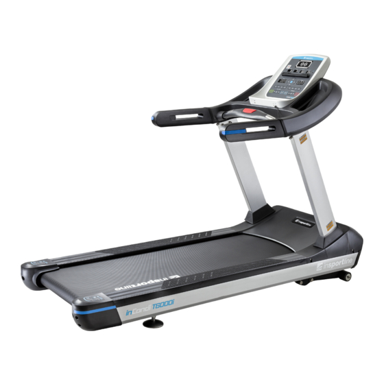
- Page 1 USER MANUAL – EN IN 13149 Motorized Treadmill inSPORTline inCondiT6000i...
-
Page 2: Table Of Contents
CONTENTS SAFETY INSTRUCTIONS ........................3 IMPORTANT ELECTRICAL INFORMATION ..................4 IMPORTANT OPERATION INSTRUCTIONS ..................4 ASSEMBLY INSTRUCTIONS ......................... 5 ASSEMBLY STEPS ..........................6 EMERGENCY BUTTON INSTRUCTIONS ................... 11 GROUNDING METHODS ........................11 OPERATION GUIDE ..........................12 EXERCISE INSTRUCTIONS ........................ 20 THE WARM UP PHASE ........................ -
Page 3: Safety Instructions
Special tips: 1. Before installation and operation, please read this operation manual carefully. 2. Please save this manual for future reference. 3. Product may vary slightly from the item pictured due to model upgrades. SAFETY INSTRUCTIONS WARNING - Read all instructions before using this treadmill. It is important your treadmill receives regular maintenance to prolong its useful life. -
Page 4: Important Electrical Information
IMPORTANT ELECTRICAL INFORMATION WARNING! 1) NEVER use a ground fault circuit interrupt (GFCI) wall outlet with this treadmill. Route the power cord away from any moving part of the treadmill including the elevation mechanism and transport wheels. 2) NEVER operate treadmill on Generator or UPS power supply. 3) NEVER remove any cover without first disconnecting AC power. -
Page 5: Assembly Instructions
ASSEMBLY INSTRUCTIONS When you open the carton, you will find the below spare parts: Parts List: DES. Specification Nos. Main Frame Left upright tube Right upright tube Bolt M10*20 Spring washer Flat Washer Console top cover Console panel Screw ST4.2*12 Left upright tube cover Right upright tube cover Left handle bar... -
Page 6: Assembly Steps
8#Allen wrench 5#Allen wrench Phillips screwdriver Assembly tools: 5#Allen wrench 5mm 1pc, 8#Allen wrench 8mm 1pc, T shape Allen wrench 6mm 1pc, Open wrench 1pc, Phillips screwdriver 1pc Notice: Do not get through power before complete assembly ASSEMBLY STEPS Step 1: 1. - Page 7 Step 2: Lift up the left and right motor side covers (13, 14) by using Phillips screwdriver (81) and ST4.2*12 screw (96). Step 3: 1. Connect the middle signal wire (47) and lower signal wire (48). 2. Fix the left and right upright tubes (C, D) to the main frame (1) with bolts M10*20 (106), spring washer (126) and flat washer (120) by using 8#Allen wrench (79).
- Page 8 2. Fix the console panel (B) to the console top cover (A) with screw ST4.2*12 (96) by using the Phillips screwdriver (81). Step 5: 1. Connect the top signal wire (46) and middle signal wire (47) first. 2. Insert the left and right upright tube covers (15, 16) into left and right upright tubes (C, D). 3.
- Page 9 Step 6: Fix left and right motor side cover (13, 14) to the motor top cover (11) with screw ST4.2*12 (96) by using Phillips screwdriver (81). Step 7: Fix the Left and right upright tube covers (15, 16) to the motor top cover (11).
- Page 10 Step8: Fix the left and right handle bar (E, F) to the console (A) with bolt M8*15(133) and washer (124) by using 5# Allen Wrench (80). Step 9: 1. Assemble the left and right handle bar (69, 70) to the console (A). 2.
-
Page 11: Emergency Button Instructions
EMERGENCY BUTTON INSTRUCTIONS Attach the clip of the safety pulling rope (64) to your cloth. For any emergency situation, press the emergency button (63) or pull out the safety pulling rope (64), the treadmill will stop immediately. GROUNDING METHODS This product must be grounded. If there is any fault, grounding can reduce the risk of electric shock. The plug of machine is equipped with grounding conductor, to ensure your safety;... -
Page 12: Operation Guide
OPERATION GUIDE WINDOW DISPLAY 1. ”Time” window: Display running time. Display the exercise time positive direction clock from 0:00 - 18 hours and 12 mins., when count to the end, the machine will not stop and count again from 0:00; when count down, it will show from the setting time to 0:00, when down to 0:00, the machine will stop smoothly and show “End”, and will enter into standby mode. - Page 13 4. “Pulse “window: When the runner holds handle pulse with two hands, the system can calculate the runner’s heart beat and window will display the runner heartbeat, the range is 50-200 beats/min (this data is just for reference, cannot be used as the medical data). 5.
- Page 14 “VOL+” Press this button can increase the volume. (Available for both MP3 and USB connection). “VOL-” Press this button can reduce the volume. (Available for both MP3 and USB connection). “PLAY/ PAUSE” button: Press this button, you can stop or restart the music. Self-lubrication function: In order to ensure a better maintenance, this machine has a self-lubrication function system, which will make the machine lubricate the running belt automatically with stored...
- Page 15 3. Press incline down will reduce the incline section. 4. Press incline up will increase the incline section. 5. Press speed shortcut button will adjust speed correspondingly. 6. Press incline shortcut button will adjust incline correspondingly. 7. Press STOP will reduce until it stopped. 8.
- Page 16 INCLINE SPEED INCLINE SPEED INCLINE SPEED INCLINE SPEED INCLINE SPEED INCLINE SPEED INCLINE SPEED INCLINE SPEED INCLINE SPEED INCLINE SPEED INCLINE SPEED INCLINE SPEED INCLINE SPEED INCLINE SPEED INCLINE SPEED INCLINE SPEED INCLINE SPEED INCLINE SPEED INCLINE...
- Page 17 SPEED INCLINE SPEED INCLINE SPEED INCLINE SELF-DEFINE PROGRAM Besides 24 inner installed programs, there are 3 user self-define programs: U1, U2, U3 1. User self-define program setting: In the initial situation, press “PROGRAM” continuously till U1,U2,U3, and the “TIME” window glitter, show the time 15:00, press “INCLINE+”, “INCLINE-”, “SPEED+”, “SPEED-”...
- Page 18 L-H: Min to Max heart rate available adjustment range 1. Press “HRC” button under standby mode, you can choose heart rate control from HP1 to HP2. HP1: The max speed will be 10.0KM/H, and the default heart rate is 120hypo/min. HP2: The max speed will be 12.0KM/H, and the default heart rate is 130hypo/min.
- Page 19 1.00 DISTANCE (KM) 0.00 0.50-99.9 0.00-99.9 PULSE (HYPO/MIN) 50-200 CALORIE (THERM) 10-999 0-999 BODY TESTER At the beginning state, press “PROGRAM” Continuously entering FAT body fat tester, press “MODE“, enter F-1, F-2, F-3, F-4, F-5 (F-1 SEX, F-2 AGE, F-3 HEIGHT, F-4 WEIGHT, F-5 FAT TESTER). Press “SPEED+”, “SPEED-”...
-
Page 20: Exercise Instructions
EXERCISE INSTRUCTIONS THE WARM UP PHASE This stage helps to get the blood flowing around the body and the muscles working properly. It will also reduce the risk of cramp and muscle injury. It is advisable to do a few stretching exercises as shown below. -
Page 21: After Each Use
WARNING: UNPLUG POWER CORD BEFORE MAINTENANCE. WARNING: STOP TREADMILL BEFORE FOLDING. AFTER EACH USE After each use, clean and inspect, following these steps: 1) Turn off the treadmill with the on/off switch, and then unplug the power cord at the wall outlet. 2) Wipe down the running belt, deck, motor cover, and console casing with a damp cloth. - Page 22 TO CENTER WALRUNNING BELT Place treadmill on a level surface Run treadmill with speed of 6kmh/3.5 mph. If the belt moves to the right, turn the right adjusting bolt quarter circle with clockwise, if the belt does not run to central position, adjust again. (Picture A) ...
-
Page 23: Exploded Drawing
EXPLODED DRAWING... -
Page 24: Parts List
PARTS LIST PART NO. Description Main Frame Incline Bracket Console Bracket Left upright tube Right upright tube Front roller Rear roller Motor belt Running desk Running belt Motor top cover Motor front cover Left motor side cover Right motor side cover Left upright tube cover Right motor trim cover Left side rail... - Page 25 Incline tube Tension bolt Tension spring AC motor Incline motor Inverter Error code board Wheel Ball bearing with prismatic base PCB board Top signal wire Middle signal wire Bottom signal wire Console top cover Console bottom cover Console middle top cover Console middle bottom cover...
- Page 26 Handle bar decoration strip Wheel bushing AC single wire Brown AC single wire Blue Magnetic ring Magnetic core T shape Allen Wrench Open Wrench 19mm 8# Allen Wrench 5# Allen Wrench Phillips screwdriver Big washer Square oil bottle Oil driving system top cover Oil driving system bottom cover...
-
Page 27: Trouble Shooting
Bolt M8*35 Bolt M8*16 Bolt M8*65 Bolt M8*80 Bolt M10*70 Bolt M8*12 Bolt M6*12 Screw ST4.2*12 Screw ST4.2*13 Screw ST4.2*20 Screw ST4.2*8 Extra-large washer C (φ11*φ34*3.0) Flat washer C Flat washer C Flat washer C Flat washer C Lock washer Lock washer Lock washer Lock washer... -
Page 28: Terms And Conditions Of Warranty, Warranty Claims
A. Please check the connection of top and middle and lower sign wires are well connected. B. Please change a new PCB board. C. Please change a new inverter. 2. Inverter problem: The inverter light will be on, please check by following steps: A. - Page 29 otherwise specified in the Purchase Agreement, in the Amendment to this Contract or in another written agreement. Warranty Conditions Warranty Period The Seller provides the Buyer Warranty for Goods Quality (60 months for the main frame and 24 months for other components), unless otherwise specified in the Certificate of Warranty, Invoice, Bill of Delivery or other documents related to the Goods.
- Page 30 VAT ID: CZ26847264 Phone: +420 556 300 970 E-mail: eshop@insportline.cz reklamace@insportline.cz servis@insportline.cz Web: www.insportline.cz INSPORTLINE s.r.o. Headquarters, Warranty & Service centre: Elektricna 6471, 911 01 Trencin, Slovakia CRN: 36311723 VAT ID: SK2020177082 Phone: +421(0)326 526 701 E-mail: objednavky@insportline.sk reklamacie@insportline.sk servis@insportline.sk Web: www.insportline.sk...
Need help?
Do you have a question about the inCondiT6000i and is the answer not in the manual?
Questions and answers