Table of Contents
Advertisement
Quick Links
Advertisement
Table of Contents

Related Manuals for Insportline IN 13150


Summary of Contents for Insportline IN 13150
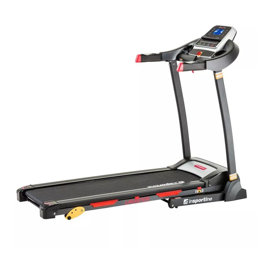
- Page 1 USER MANUAL – EN IN 13150 Motorized treadmill inSPORTline Lavister...
-
Page 2: Table Of Contents
CONTENTS IMPORTANT SAFETY INSTRUCTIONS ....................3 IMPORTANT ELECTRICAL INFORMATION ..................4 IMPORTANT OPERATION INSTRUCTIONS ..................4 ASSEMBLY INSTRUCTIONS ......................... 6 ASSEMBLY STEPS ..........................7 FOLDING INSTRUCTION ........................11 GROUNDING METHODS ........................11 COMPUTER INSTRUCTIONS ......................12 BUTTON FUNCTION ..........................13 EXERCISE INSTRUCTIONS ........................ -
Page 3: Important Safety Instructions
Special tips: 1. Before installation and operation, please read this operation manual carefully. 2. Please save this manual for future reference. 3. Product may vary slightly from the item pictured due to model upgrades. IMPORTANT SAFETY INSTRUCTIONS WARNING - Read all instructions before using this treadmill. It is important your treadmill receives regular maintenance to prolong its service life. -
Page 4: Important Electrical Information
22) WARNING! The heart rate frequency monitoring may not be completely accurate. Overexertion during training can lead to a serious injury or even death. If you start to feel faint, stop the exercise immediately. Remove the safety key after use to prevent unauthorized treadmill operation. IMPORTANT ELECTRICAL INFORMATION WARNING! 1) NEVER use a ground fault circuit interrupter (GFCI) wall outlet with this treadmill. - Page 5 Warning: Now here we suggest that you should consult with your physician or health professional before starting your workout, especially for the age up to 35 old or once-health problem people. We take no responsibility for any troubles or hurts if you don’t follow our specifications. Treadmill will be carefully assembled and covered by the motor shield, then connect to the power.
-
Page 6: Assembly Instructions
ASSEMBLY INSTRUCTIONS When you open the carton, you will find the below spare parts: Spare parts list: DES. Specification Nos. MAIN FRAME WRENCH W/SCREW S=13,14,15 DRIVER 5#ALLEN WRENCH 5 mm BOTTLE HOLDER SAFETY KEY LEFT UPRIGHT TUBE COVER RIGHT UPRIGHT TUBE COVER BOLT M5*12... -
Page 7: Assembly Steps
ASSEMBLY STEPS ASSEMBLY STEP 1: Open the carton and remove contents. Place the Main Frame (A) on level ground, ensure that you have a work area that is clean and has adequate space. Please do not cut packing belt (F) before you finish assembly. ASSEMBLY STEP 2: Lift up the console (B) and left &... - Page 8 ASSEMBLY STEP 3: Use the 5# Allen wrench (B08) and M8*15 bolt (E09) and lock washer (E25), lock the left & right upright tube (A04, A05) onto main frame (A01). ASSEMBLY STEP 4: Use the 5# Allen wrench (B08) and M8*15 bolt (E09) and lock washer (E25), lock the console (B) onto the left and right upright tube (A04, A05).
- Page 9 ASSEMBLY STEP 5: Push the Left & Right upright tube covers (C11, C12) onto the base frame (A01) and Left & Right upright tube (A04, A05). ASSEMBLY STEP 6: Put the bottle holder (C30) into the console (B) kettle slot. NOTE: Please insert the bottle holder of slot side along with the gap H.
- Page 10 ASSEMBLY STEP 7: Cut Packing Belt (F) after finish the assembly of the treadmill. ASSEMBLY STEP 8: Before running, please insert the Safety Key (C06) into the magnetic area of the Console (B) and fasten the safety key clip (C06) with your clothes.
-
Page 11: Folding Instruction
FOLDING INSTRUCTION Pulling up: Support place K with a hand, and then pull up in the direction of the arrow, until hearing that the CYLINDER (J) is locked into the round tube. Pulling down: Support place K with a hand, press the frame slightly, then kick the place J, and the base frame will fall down automatically. -
Page 12: Computer Instructions
This product is for use on a nominal voltage circuit and has a grounding plug that looks like the plug illustrated in sketch A in following figure. Make sure that the product is connected to an outlet having the same configuration as the plug. No adapter should be used with this product. COMPUTER INSTRUCTIONS WINDOW DISPLAY SPEED/ PULSE: Displays the speed. -
Page 13: Button Function
it will count from the setting time to 0:00. When the clock reaches 0:00, the machine will stop smoothly and display “End” and then automatically reset to the initial setting after 5 seconds. CALORIES: Displays the amount of calories the runner has burned. Calories will count from 0 to 999. When the count reaches 999, it will reset and start back from 0 again. - Page 14 2. Press START/STOP button and the system will enter into 3 seconds count down, the buzzer will chime and the speed window will display a count down. The belt will run at 1.0 km/h after 3 seconds. 3. After start-up, you can use speed up or down to adjust the speed and use incline up or down to adjust the incline.
- Page 15 PROGRAM EXERCISE CHART TIME INTERVAL = SETTING TIME/10 SPEED SPEED SPEED SPEED SPEED SPEED SPEED SPEED SPEED SPEED SPEED SPEED RANGE OF PROGRAM PROGRAM ORIGINAL SET UP DISPLAY RANGE RANGE TIME (MIN: 0:00 10:00 5:00 - 99:00 0:00 - 99:59 SECOND) SPEED (KM/H) 1.0 - 14.0...
-
Page 16: Exercise Instructions
01 male 02 female 10 - 99 Height 100 - 200 Weight 20 - 150 ≤19 Underweight = (20 - 25) Normal weight = (26 - 29) Overweight ≥30 Obesity SAFETY KEY FUNCTION If you pull out the safety pulling rope, the treadmill will stop immediately. All the windows will display “―――”... -
Page 17: The Cool Down Phase
This stage should last a minimum of 12 minutes though most people start at about 15 - 20 minutes. THE COOL DOWN PHASE This stage is to let your Cardio-vascular System and muscles wind down. This is a repeat of the warm up exercise e.g. -
Page 18: Centering The Running Belt
CENTERING THE RUNNING BELT Place the treadmill on level ground and set it at 3 - 5 km/h to check if the running belt drifts. If the running belt moves to the right, turn the adjusting bolt on the right side ¼ turn clockwise, then turn the left adjustment bolt ¼... -
Page 20: Exploded Drawing
EXPLODED DRAWING... -
Page 21: Parts List
PARTS LIST Q’ty Description Specification BASE FRAME MAIN FRAME CONSOLE FRAME LEFT UPRIGHT TUBE RIGHT UPRIGHT TUBE DC MOTOR BRACKET FRONT ROLLER BACK ROLLER CYLINDER IRON SHEET TURNING BUSHING FIX PIN WRENCH W/SCREW DRIVER S=13,14,15 5# ALLEN WRENCH 5 mm SPEAKER NET CONSOLE TOP COVER CONSOLE PANEL... - Page 22 WHEEL COVER ADJUSTABLE FOOT PAD RING PROTECTING WIRE PLUG FOOT PAD CYLINDRICAL PLUG BLUE CUSHION WIRE BUCKLE RUBBER PAD ADJUSTABLE RUBBER PAD BOTTLE HOLDER IPAD HOLDER COMPUTER BOARD CONTROL BOARD KEYBOARD KEYBOARD CONNECTING WIRE TOP SIGNAL WIRE MIDDLE SIGNAL WIRE BOTTOM SIGNAL WIRE PULSE WITH /START&STOP PULSE WITH SPEED...
- Page 23 SIGNAL WIRE GROUNDING WIRE INDUCTANCE CONNECTING BOARD BOLT M5*8 SCREW ST4.2*12 SCREW ST2.9*6.0 AUDIO OUTPUT & INPUT CABLES AUDIO MODULE FIXED CAP AUDIO CONNECTING WIRE SPEAKER MP3 WIRE USB POWER WIRE if available only USB MODULE if available only AUDIO CONTROL WIRE USB OUTPUT CABLES if available only BLUETOOTH MODULE...
-
Page 24: Trouble Shooting Guide
SCREW ST2.9*6 SCREW ST4.2*12 φ26*φ10*2.0 WASHER WASHER WASHER WASHER WASHER SCREW ST2.9*4 SCREW ST3.5*10 TROUBLE SHOOTING GUIDE 1. There is no display on screen after the machine is connected to the power source a. Please check the overload button, if the overload protector button bounces, please press this button;... -
Page 25: Terms And Conditions Of Warranty, Warranty Claims
6. E05 on display: Overload current protection a. If the current is too strong, the system will protect itself by shutting down. Please restart the machine. b. It is possible a part of the machine is locked which caused a problem with the motor. Please add oil to the machine and restart. - Page 26 Borivojova 35/878, 130 00 Praha 3, Czech Republic Headquarters: Delnicka 957, 749 01 Vitkov, Czech Republic Warranty & Service Centre: Cermenska 486, 749 01 Vitkov, Czech Republic CRN: 26847264 VAT ID: CZ26847264 Phone: +420 556 300 970 E-mail: eshop@insportline.cz reklamace@insportline.cz...
- Page 27 Web: www.insportline.cz INSPORTLINE s.r.o. Headquarters, Warranty & Service centre: Elektricna 6471, 911 01 Trencin, Slovakia CRN: 36311723 VAT ID: SK2020177082 Phone: +421(0)326 526 701 E-mail: objednavky@insportline.sk reklamacie@insportline.sk servis@insportline.sk Web: www.insportline.sk Date of Sale: Stamp and Signature of Seller:...
Need help?
Do you have a question about the IN 13150 and is the answer not in the manual?
Questions and answers