Table of Contents
Advertisement
Quick Links
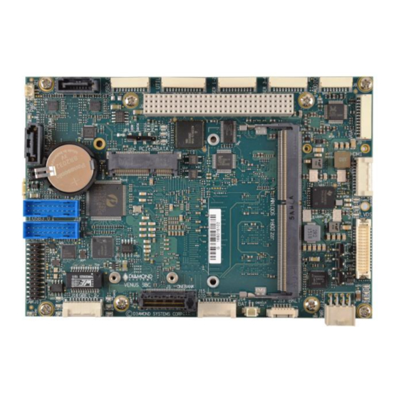
Venus Single Board Computer
with Intel "Skylake" Core i7 6th Generation Processor
Revision
1.00
1.1a
1.1b
1.1c
1.1d
1.1e
FOR TECHNICAL SUPPORT
PLEASE CONTACT:
support@diamondsystems.com
Venus User Manual Rev 1.1d
3.5" Form Factor SBC
Date
03/13/2017
Initial Release
06/20/2017
Power Supply and Thermal Solutions
section updated.
08/24/2017
Updated JP2 jumper section
08/31/2017
Updated Digital IO spec and connector
mating parts
09/11/2017
Updated default jumper settings and Video
features
10/06/2017
RTC battery details are added
www.diamondsystems.com
Comment
Diamond Systems Corporation
158 Commercial Street
Sunnyvale, CA 94086 USA
www.diamondsystems.com
Copyright 2017
Tel 1-650-810-2500
Fax 1-650-810-2525
Page 1
Advertisement
Table of Contents

Related Manuals for Diamond Systems Venus VNS766-4GD


Summary of Contents for Diamond Systems Venus VNS766-4GD
- Page 1 09/11/2017 Updated default jumper settings and Video features 1.1e 10/06/2017 RTC battery details are added Copyright 2017 FOR TECHNICAL SUPPORT Diamond Systems Corporation PLEASE CONTACT: 158 Commercial Street Sunnyvale, CA 94086 USA support@diamondsystems.com Tel 1-650-810-2500 Fax 1-650-810-2525 www.diamondsystems.com Venus User Manual Rev 1.1d www.diamondsystems.com...
-
Page 2: Table Of Contents
CONTENTS Important Safe Handling Information ......................4 Introduction ...............................6 Standard Configurations ..........................6 Features .................................6 Operating System Support ..........................7 Mechanical, Electrical, Environmental ......................7 Functional Block Diagram ..........................8 Feature Descriptions .............................9 3.1.1 Processor and Chipset ..........................9 3.1.2 Memory ..............................9 3.1.3 Ethernet..............................9 3.1.4 SATA ..............................9 3.1.5 USB ...............................9 3.1.6... - Page 3 LED ................................32 Quiet / Quick Boot / Splash Screen ......................32 Serial Port Configuration ..........................32 Getting Started ............................... 33 10.1 Development Kit ............................33 10.2 Quick Setup ..............................33 10.3 Boot Device Options ........................... 33 10.4 Installing OS and Booting ........................... 34 Video Features ...............................
-
Page 4: Important Safe Handling Information
This creates many opportunities for accidental damage during handling, installation and connection to other equipment. The list here describes common causes of failure found on boards returned to Diamond Systems for repair. This information is provided as a source of advice to help you prevent damaging your Diamond (or any vendor’s) embedded computer boards. - Page 5 Overvoltage on analog input – If a voltage applied to an analog input exceeds the design specification of the board, the input multiplexor and/or parts behind it can be damaged. Most of our boards will withstand an erroneous connection of up to 35V on the analog inputs, even when the board is powered off, but not all boards, and not in all conditions.
-
Page 6: Introduction
2 INTRODUCTION Venus is a 3.5” standard SBC based on 6th generation Intel Skylake processor i7-6600U. The U-series processors are offered in a 1-chip platform that includes the 6th generation Intel Platform Controller Hub (PCH) die on the same package as the processor die. Board provides expansion option over One bank PCIe/104 and PCI-104 connector. -
Page 7: Operating System Support
2.3 Operating System Support Windows 10, 8, 7, Linux Driver packages and/or BSPs available for each OS 2.4 Mechanical, Electrical, Environmental 3.5” Standard form factor (146 x 102mm / 5.75” x 4.00”) Form factor Cooling Conduction cooling, bottom side heat spreader Power input +9V to +18VDC in;... -
Page 8: Functional Block Diagram
3 FUNCTIONAL BLOCK DIAGRAM BLOCK DIAGRAM Gigabit DDR4 Memory DDR4 CH1 Magnetics SML0 Intel I219 Ethernet Down 4GB Gigabit MAC/PHY PCIe x1 Magnetics DDR4 SODIMM DDR4 CH2 Ethernet Intel I210 4GB/8GB/16GB 1x USB 2.0 Mini PCIe / DDI1 HDMI mSATA PCIe x1 Socket DDI2... -
Page 9: Feature Descriptions
3.1 Feature Descriptions This section describes the key subsystems of the Venus SBC. 3.1.1 Processor and Chipset Venus is based on 6th generation Intel Skylake processor i7-6600U. The U-series processors are offered in a 1- chip platform that includes the 6th generation Intel Platform Controller Hub (PCH) die on the same package as the processor die. -
Page 10: Video
3.1.6 Video The board offers three video output options: HDMI, VGA and LVDS LCD. The HDMI port is directly from the processor and is made available on a dual row 1.25mm pitch latching connector. VGA is realized from the processor’s DisplayPort (DP) port using a DP to VGA bridge chip and is available on a 1.25mm pitch latching connector. -
Page 11: Pcie Minicard Socket
3.1.12 PCIe Minicard Socket The board has two full size (51mm length) PCIe Minicard socket. The top side socket supports both PCIe Minicard and mSATA modules. A PCIe/mSATA switch is used to auto select which interface is active based on the state of CLKREQ# pin driven by an installed module. -
Page 12: Bios Features
3.1.16 BIOS Features The Venus BIOS provides the following user configurable and controllable features: Boot from LAN (PXE) as well as USB and SATA ports Free boot sequence configuration to allow different boot sequences as first, second and third boot devices Support multi display mode. -
Page 13: Power Supply
3.1.18 Power Supply The board will operate with an input voltage in the range 9VDC to 18VDC. Nominal input voltage is +12VDC. Typical operating power consumption is in the range of 13-14W (1.1-1.2A at 12V). The supports ACPI for pushbutton on/off control and also supports standby mode. In standby mode, the board may be powered on via the Wake on Lan feature or using a power button. -
Page 14: Mechanical Board Drawing
4 MECHANICAL BOARD DRAWING Dimensions are in inches [mm]. Connector dimensions indicate the center of the pad for pin 1 (pin A1 for the PCI- 104 connector). Figure 2: Mechanical Board Drawing Venus User Manual Rev 1.1d www.diamondsystems.com Page 14... -
Page 15: Board Layout (Connector And Jumper Locations)
5 BOARD LAYOUT (CONNECTOR AND JUMPER LOCATIONS) J4 JP1 Block 2 Block 1 Block 3 Block 4 Block 7 Block 5 Block 6 Venus User Manual Rev 1.1d www.diamondsystems.com Page 15... - Page 16 I/O Connectors, Jumpers and LED Summary Connec Function Jumper Function PC/104 SATA DOM/Cable selection, PCI I/O Express Voltage selection – PC/104 LVDS Vcc & Backlight, Digital IO voltage PLUS PCI and pull resistors SATA port 2 USB 2.0 Port LED Block 1 Utility SATA Activity Connector...
-
Page 17: O Connectors
6 I/O CONNECTORS 6.1 Connector Pin-out and Signal Description 6.1.1 Power In (J12) Vin is 9-18VDC (12VDC nominal). Ground Ground Ground Ground Connector used is a custom version of Samtec IPL1. Mating Cable: DSC 6980512 6.1.2 External Battery (J14) VBAT Ground VBAT = +3.0V Connector used is 22-05-7025 right angle type friction lock pin header. - Page 18 Venus User Manual Rev 1.1e www.diamondsystems.com Page 18...
-
Page 19: Usb 3.0 Port (J18, J19)
6.1.4 USB 3.0 Port (J18, J19) There are two USB3.0 headers with identical pinouts Each USB3.0 header also provides access to two USB 3.0 ports with USB 2.0 backward compatibility. The pinout for the connector is compatible with the Intel standard for USB 3.0 motherboard connectors. -
Page 20: Sata (J3)
6.1.7 SATA (J3) A standard 7 Pin SATA connector is used for external SATA storage devices. Ground SATA 1 TX+ SATA 1 TX- Ground SATA 1 RX- SATA 1 RX+ Ground 6.1.8 SATA/DOM (J20) A second standard 7 pin SATA connector is provided for either an external SATA device or a board-mounted SATA-DOM storage device. -
Page 21: Lvds Lcd (J11)
6.1.11 LVDS LCD (J11) VDD 5V/3.3V VDD 5V/3.3V VDD 5V/3.3V VDD 5V/3.3V CLK+ Odd CLK+ Even CLK- Odd CLK-Even Ground Ground D0+ Odd D0+ Even D0- Odd D0- Even D1+ Odd D1+ Even D1- Odd D1- Even D2+ Odd D2+ Even D2- Odd D2- Even D3+ Odd... -
Page 22: Hdmi (J10)
6.1.14 HDMI (J10) Data 2+ Ground Data 2- Data 1+ Ground Data 1- Data 0+ Ground Data 0- Clock+ Ground Clock- CEC (NC) Reserved DDC Clock DDC Data Ground Hot Plug Detect Chassis ground Connector used is SM20B-GHDS-GAN-TF. Side entry type friction lock pin header. 6.1.15 Digital I/O (J15) VIO (fused) DIO A0... -
Page 23: Msata / Pcie Minicard Socket (J23, J24)
6.1.17 mSATA / PCIe MiniCard Socket (J23, J24) Two mini card sockets are used. One is used for PCIe mini card interface and other socket can be used for both PCIe MiniCard and mSATA disk module. The configuration is selected with a switch that is controlled by pin 7. A PCIe Minicard will tie pin 7 to ground, while an mSATA module will leave pin 7 open. -
Page 24: Pcie/104 (J1)
6.1.18 PCIe/104 (J1) This connector is implemented to facilitate I/O expansion modules to be plugged onto Venus SBC. Note that, 3 nos of x1 PCIe lanes are connected to the One bank PCIe/104 connector. USB-OC# PCIe Reset# +3.3V +3.3V USB_1+ USB_0+ USB_1- USB_0-... - Page 25 6.1.19 PCI-104 (J2) The board contains a non-stack through / short pin PCI-104 connector on the top side in the standard position as described by the PC/104-Plus specification. GND/5.0V KEY Reserved AD00 VI/O AD02 AD01 AD05 AD04 AD03 C/BE0* AD07 AD06 AD09 AD08...
-
Page 26: Pci-104 (J2)
6.2 List of Connectors The following table provides a summary of all I/O connectors on the board. Function Manufacturer Part no. Description Mating part Mating Cable Power in Samtec ASP-194529-01 header IPD1-04-D-K 6980512 Right angle .1” pitch External Molex 22-05-7025 2 pos. -
Page 27: O Cables
7 I/O CABLES Photo No: Cable Part No Description Venus Connector 6980514 Utility 6980517 Digital I/O 6980507 6980508 Audio 6989101 SATA J20, J3 6980513 Ethernet 6980500 Serial ports J6, J7 6980100 USB 3.0 J18, J19 6980503 USB 2.0 6980524 Battery 6980512 Power in 6980519... -
Page 28: Jumper Description
8 JUMPER DESCRIPTION Following drawing shows only the connectors and jumper blocks on the board. The default jumper positions are shown in blue. Figure 3 Default Jumper locations Jumper Description SATA DOM Power, PCI VIO LVDS LCD VCC and Backlight 8.1 SATA DOM Power / PCI VIO (JP1) The 7th pin of the SATA connector J20 can be configured for SATA DOM or for SATA cable. -
Page 29: Lvds Backlight And Lvds Vdd (Jp2)
Figure 4 Jumper Block JP1 The following table shows the different combinations of jumper block JP1. The row in bold and italics shows the default configuration of jumper block JP1. Note: 1. Jumpers should be installed in either positions 4-5 or 5-6. 8.2 LVDS Backlight and LVDS VDD (JP2) Jumper block JP2 configures the voltage supply for the LCD backlight, LVDS VDD and DIO Voltage as well. - Page 30 Figure 5 Jumper Block JP2 The following table shows different combinations of jumper locations on JP2. LVDS LVDS Backlight 3.3V 3.3V DIO Voltage 3.3V Note: 1. Voltage supply on LVDS backlight will not depend on or affect the voltage input of LVDS. 2.
-
Page 31: Bios Key Features
9 BIOS KEY FEATURES The BIOS on Venus provides access to many valuable features. These instructions show how to enter the BIOS and set up features. 9.1 Entering the BIOS The BIOS may be entered during startup by pressing the DEL key on an attached keyboard. Press the key repeatedly soon after a power-on or reset until the BIOS screen appears. -
Page 32: Led
9.6 LED A green BIOS LED has been provided to indicate that the board has been booted to BIOS GUI. The location of the BIOS LED is being shown in the Board Layout Section. 9.7 Quiet / Quick Boot / Splash Screen Quiet boot replaces the system status and configuration screen that appears during startup with a blank screen or custom splash screen (if available). -
Page 33: Getting Started
10 GETTING STARTED This section describes the steps needed to get Venus SBC up and running, and assumes that user also has a Venus Development Kit or Venus Cable Kit. The Cable Kit includes all cables needed for the I/O, except the LCD and backlight. -
Page 34: Installing Os And Booting
10.4 Installing OS and Booting Ensure that SATA data cable and power cable are connected to SATA HDD. Follow below steps to install Windows 8.1/10 operating system in SATA HDD. Connect a USB pen drive to a USB port of (J4) Venus board having Windows 10 installation image. Boot the Venus board to BIOS. -
Page 35: Video Features
11 VIDEO FEATURES Venus SBC offers three video output options: 2 DDI and one eDP. The DDI ports are configurable for either HDMI 1.4, DP 1.1a, or eDP. All the three outputs can be active at any time. DDI port 1 is configured as HDMI 1.4 and supports a maximum resolution of 1920 x 1080 x 60Hz x 24bpp. DDI port 2 is used for VGA and VGA is realized using DP to VGA converter. -
Page 36: Serial Ports And System Console
12 SERIAL PORTS AND SYSTEM CONSOLE 12.1 Configuration Venus SBC supports total 4 serial ports. All the 4 ports support RS-232/422/485 modes. The modes can be configured in BIOS. Both TX and RX termination selection option are available under BIOS menu. 12.2 Console redirection Connect any of the Venus serial ports to PC. -
Page 37: Digital I/O
13 DIGITAL I/O The 16 digital I/O lines are realized using the I2C to GPIO expander and are available on external header (J15). The digital I/O voltage can be configured as either +3.3V or 5V via jumper settings. The digital I/O lines can be software-configured for pull-up / down resistors. -
Page 38: Software Driver Overview
SATA DOM installed with either Windows 10 or Linux. All the necessary I/O drivers are also available as part of the Development Kit. Please contact Diamond Systems for more details. Some of the drivers that are required with the Windows 10 operating system are given below. These drivers are available for download from Diamond Systems’... -
Page 39: Thermal Solutions
15 THERMAL SOLUTIONS Venus SBCs come with a heat spreader which is mounted on the bottom side of the board The mechanical drawing of the heat spreader and the drawing for the heat spreader installed on the board are shown below. 15.1 Heat Spreader Drawing Figure 6 Mechanical Drawing of the Heat Spreader (Bottom View) 15.2 Mounting Hole Specifications. -
Page 40: Heat Spreader Installation
15.3 Heat Spreader Installation Observe ESD safe handling procedures always. 1. Inspect the Heat Spreader and make sure thermal pads are in good condition. 2. Remove all thermal pad liners from bottom of heat spreader. Avoid any contamination of exposed thermal pad surfaces. -
Page 41: Heat Spreader Installed On The Board
15.4 Heat Spreader Installed on the Board Figure below shows the side view of the heat spreader installed on the Board Figure 9 Heat Spreader Installed on the board. Venus User Manual Rev 1.1e www.diamondsystems.com Page 41... -
Page 42: Heat Spreader With Brackets Installed On The Board
15.5 Heat Spreader with brackets Installed on the Board Figure below shows the side view of the heat spreader with the bracket installed on the Board Figure 10 Heat Spreader with Bracket Venus User Manual Rev 1.1e www.diamondsystems.com Page 42... -
Page 43: Specifications
16 SPECIFICATIONS Item VNS766-4GD VNS563-4GD Processor 2.6 GHz dual core Skylake i7-6600U 2.4GHz dual core Skylake i5-6300U Speed 2.6GHz 2.4GHz Cooling Heat Spreader System bus SDRAM memory Up to 20GB DDR4 4GB onboard + upto 16GB via SODIMM Display type HDMI Dual Channel LVDS LCD USB ports...
Need help?
Do you have a question about the Venus VNS766-4GD and is the answer not in the manual?
Questions and answers