Anritsu Site Master S331L User Manual
Handheld cable and antenna analyzer featuring
classic and advanced modes
Hide thumbs
Also See for Site Master S331L:
- Maintenance manual (44 pages) ,
- Scpi programming manual (96 pages)
Table of Contents
Advertisement
Quick Links
User Guide
Site Master™
S331L User Guide
Handheld Cable and Antenna Analyzer Featuring
Classic and Advanced Modes
2 MHz to 4 GHz Cable & Antenna Analyzer
50 MHz to 4 GHz Power Meter
Anritsu Company
Part Number: 10580-00321
490 Jarvis Drive
Revision: M
Morgan Hill, CA 95037-2809
Published: July 2017
USA
Copyright 2017 Anritsu Company
http://www.anritsu.com
Advertisement
Table of Contents

Related Manuals for Anritsu Site Master S331L


Summary of Contents for Anritsu Site Master S331L
- Page 1 Classic and Advanced Modes 2 MHz to 4 GHz Cable & Antenna Analyzer 50 MHz to 4 GHz Power Meter Anritsu Company Part Number: 10580-00321 490 Jarvis Drive Revision: M Morgan Hill, CA 95037-2809 Published: July 2017 Copyright 2017 Anritsu Company http://www.anritsu.com...
-
Page 3: Table Of Contents
Additional Documents ..... . 1-2 Contacting Anritsu for Sales and Service ..1-3 Instrument Description ......1-3 Available Options . - Page 4 Table of Contents (Continued) Touchscreen Display Overview ....2-12 Main Menu Keys ......2-13 Submenu Keys .
- Page 5 Table of Contents (Continued) Trace ........3-44 Measurement Review .
- Page 6 Table of Contents (Continued) General Measurement Setup ....5-3 Connection and Offset..... . . 5-3 Set the Measurement Frequency .
- Page 7 Table of Contents (Continued) MA24105A Inline Power Sensor ....6-12 Introduction ......6-12 In-Line Sensor Setup .
- Page 8 Table of Contents (Continued) Calibration Procedures......7-5 Calibration Procedure ..... . . 7-5 Cal Info .
- Page 9 10-3 Battery Replacement......10-2 Chapter 11—Anritsu Tool Box 11-1 Introduction ....... . 11-1 11-2 Line Sweep Tools (LST) .
- Page 10 Table of Contents (Continued) 12-4 Operation ........12-6 VIP Image Analysis .
-
Page 11: Chapter 1-General Information
Antenna measurements. About this Manual This chapter provides a general overview and information about the Site Master S331L Cable and Antenna Analyzer and a description of manual conventions, additional documents, preventive maintenance, and annual verification requirements. Chapter 2, “Instrument Overview”... -
Page 12: Document Conventions
• Site Master S331L Product Brochure (11410-00640). Includes an overview of the of the Site Master S331L instrument, ordering information, and accessories information. PN: 10580-00321 Rev. M S331L UG... -
Page 13: Contacting Anritsu For Sales And Service
Instrument Description The Site Master S331L is a one-port, 2 MHz to 4 GHz hand held cable and antenna analyzer designed to make Return Loss, VSWR, Cable Loss, Distance-To-Fault (DTF), and power measurements in the field. -
Page 14: Available Options
1-2 Instrument Description General Information Anritsu Line Sweep Tools (LST) can be used with the Site Master to create reports, view and organize data, edit markers and limit lines, and perform trace analysis. LST is available for download on the Anritsu website. -
Page 15: Battery Information
The batteries are charged in the instrument and only removed for replacement. Use only Anritsu-approved batteries, adapters, and chargers with this instrument. The batteries will charge at a faster rate when the instrument is turned off or is set to standby mode. Charging the batteries... -
Page 16: Instrument Care And Preventive Maintenance
1-3 Instrument Care and Preventive Maintenance General Instrument Care and Preventive Maintenance Site Master preventive maintenance consists of cleaning the unit and inspecting and cleaning the RF connectors on the instrument and all accessories. Clean the Site Master with a soft, lint-free cloth dampened with water or water and a mild cleaning solution. -
Page 17: Rf Input Warning
The instrument will require a new calibration if the internal instrument temperature changes more than ±20 ºC after calibration. Anritsu recommends an annual calibration and performance verification of the Site Master by local Anritsu service centers. Anritsu service also recommends a semi-annual verification of OSL calibration components. S331L UG... -
Page 18: Secure Environment Workplace
1-5 Secure Environment Workplace General Information The Site Master is self-calibrating and there are no field-adjustable components. The OSL calibration components and the Internal InstaCal are crucial to the integrity of the user calibration. As a result, they must be verified periodically to ensure performance conformity. This is especially important if the OSL calibration components have been accidentally dropped or over-torqued. -
Page 19: Erase All User Files In Internal Memory
General Information 1-5 Secure Environment Workplace Erase All User Files in Internal Memory Perform a Master Reset: 1. Press the Preset (9) button. 2. Press the Reset drop down submenu then press the Reset button. Select Master Reset and read the description on the screen (Figure 1-1). -
Page 20: Usage In A Secure Environment
1-5 Secure Environment Workplace General Information Usage in a Secure Environment Not all USB flash drives are compatible with the S331L. Anritsu recommends performing a full FAT 32 long format prior to use Note with the instrument. Some USB devices may not be recognized even after formatting, in these cases the device must be replaced with another type. - Page 21 General Information 1-5 Secure Environment Workplace 3. Press the Location button then double-tap on the word DRIVE press the left arrow key until the external USB drive is displayed. Figure 1-4. Choose a Storage Drive 4. Double-tap on USB. The Location breadcrumb will change to DRIVE : USB.
- Page 22 1-5 Secure Environment Workplace General Information 1-12 PN: 10580-00321 Rev. M S331L UG...
-
Page 23: Chapter 2-Instrument Overview
Chapter 2 — Instrument Overview Introduction This chapter provides an overview of the Anritsu Site Master S331L. The intent of this chapter is to acquaint the user with the instrument and general functionality. For detailed line sweeping information, refer Chapter 3... - Page 24 2-2 Turning On the Site Master Instrument Overview Momentarily pressing the On/Off button when the Site Master is operating will place the instrument into standby mode. A message “Going into Standby Mode” will be displayed and the touchscreen display will turn off. The green power LED will slowly pulse when the instrument is in standby mode.
- Page 25 Instrument Overview 2-2 Turning On the Site Master 1 Status Tool Bar 2 System Function Tool Bar (not available in Classic mode) 3 RF Out/Reflect In Connector 4 Power Meter/Internal InstaCal Connector 5 Menu Key 6 Rotary Knob 7 Enter Key and Arrow Keys 8 ESC Key 9 Numeric Keypad and Menu Keys 10 Charge LED...
-
Page 26: Test Panel Connector Overview
17 Measurement Settings Summary (touchscreen menu shortcuts) Figure 2-1. Site Master Instrument Overview (2 of 2) Test Panel Connector Overview The test panel for the Site Master S331L is shown in Figure 2-2. 1 RF Out/Reflect In port (Type N, Female) – 50 ohm impedance;... - Page 27 When connecting the Site Master to a local area network, use an Anritsu-approved USB-to-RJ45 adapter. The instrument will obtain an IP address via DHCP, or a static IP address can be set by the user. Refer to “Status Menu”...
-
Page 28: Front Panel Overview
The rotary knob, the four arrow keys, and the keypad can also be used to change the value of most active parameters. The Site Master S331L is shipped with a Stylus Pen that can be used for touchscreen entry. The Site Master is also compatible with a standard corded USB mouse. -
Page 29: S331L Ug Pn: 10580-00321 Rev. M
Instrument Overview 2-4 Front Panel Overview The shortcut icons on the left of the Menu screen are available for direct access. These shortcuts do not appear in Classic mode and are therefore not available for direct access. The shortcuts are only available in Classic mode by pressing the Menu key. - Page 30 2-4 Front Panel Overview Instrument Overview 1 Installed Measurement Modes 2 Close Box 3 Icon to Launch easyTest. Refer to “easyTest Tools” on page 11-2. 4 Help for Menu Screen 5 Installed Setup and Menu Shortcuts (Screen 1 of 3) 6 Shortcuts Displayed in All Menus (not available in Classic Mode) Figure 2-4.
-
Page 31: Keypad Menu Keys (1 To 9)
Instrument Overview 2-4 Front Panel Overview ESC Key Press this key to cancel any setting that is currently being made or to close the currently dialog box. Enter Key Press this key to finalize data input or select a highlighted item from a list. - Page 32 2-4 Front Panel Overview Instrument Overview Table 2-1. Site Master Keypad Functions (1 of 2) Menu Description Displays options to view information about the instrument Help status, an on screen list of Frequently Asked Questions (FAQ) and the User Guide in .html format. Refer to Chapter Allows the user to save, recall, copy, and delete files in File...
-
Page 33: Led Indicators
Instrument Overview 2-4 Front Panel Overview Table 2-1. Site Master Keypad Functions (2 of 2) Menu Description Opens the Save menu to allow for quick saving of the current Save measurement, setup, or screen shot of the current display to internal memory or an external USB device. -
Page 34: Touchscreen Display Overview
Figure 2-5 illustrates some of the Site Master user interface features. 1 Anritsu Logo. Displays the System Status dialog screen. Press ESC to close. Refer to the “Status Menu” on page 9-15 additional information. -
Page 35: Main Menu Keys
Instrument Overview 2-5 Touchscreen Display Overview 6 Expanded submenu. Expanded submenus display the function buttons. 7 Active trace sweeping between Start Frequency (F1) and Stop Frequency (F2). 8 Marker Table. Refer to “Markers” on page 3-37. 9 Marker 1. 10 Main Menu keys with Freq/Dist selected. Refer to “Main Menu Keys ”... - Page 36 2-5 Touchscreen Display Overview Instrument Overview Figure 2-6, the Measurement main menu is selected (Green depressed state) and the Return Loss measurement button is selected (Green semicircle). Figure 2-6. Return Loss Measurement 2-14 PN: 10580-00321 Rev. M S331L UG...
-
Page 37: Submenu Button Types
Instrument Overview 2-5 Touchscreen Display Overview Submenu Button Types The Site Master interface uses several submenu button types. Each is described below in Table 2-2. Table 2-2. Submenu Button Examples (1 of 2) Button Description Button Example 1. Numeric Entry Start Frequency (F1) example: 2000 MHz... -
Page 38: Instrument Overview
2-5 Touchscreen Display Overview Instrument Overview Table 2-2. Submenu Button Examples (2 of 2) Button Description Button Example 3. Parameter Value Standard Standa example: Measurement main menu. Return Loss Return This button is used when there are several options for the parameter. The current value is indicated by the glowing Return Loss green semicircle at the left of the button. -
Page 39: Status Tool Bar
Instrument Overview 2-5 Touchscreen Display Overview Status Tool Bar The Status Tool Bar includes icons to display the current time and date, battery charge, GPS status, and screen lock state. Tap one of the icons for additional information. Figure 2-7 shows the icons that are displayed in the Status Tool Bar area. - Page 40 (Figure 2-9) and screen captures. GPS status icon states: a. GPS module (H/W) is not connected. Connect an Anritsu approved GPS module. b. H/W connected without a current location fix. Module attempts to establish a location fix during this state.
- Page 41 Instrument Overview 2-5 Touchscreen Display Overview Use only Anritsu-approved batteries, adapters, and Caution chargers with this instrument. Figure 2-8. GPS Info Figure 2-9. Location Data Saved in Measurement File S331L UG PN: 10580-00321 Rev. M 2-19...
-
Page 42: System Function Tool Bar
2-5 Touchscreen Display Overview Instrument Overview System Function Tool Bar The System Function Tool Bar icons allow quick access to functions that are not measurement specific. Figure 2-10 shows the icons that are displayed in the Status Tool Bar Area (not available in Classic mode). 1 Preset icon. -
Page 43: S331L Ug Pn: 10580-00321 Rev. M
Instrument Overview 2-5 Touchscreen Display Overview Figure 2-11. Mode Selector Table Standard View Full Screen View Figure 2-12. Comparison of Standard Mode vs. Full Screen Mode S331L UG PN: 10580-00321 Rev. M 2-21... -
Page 44: Dual Display Format
2-5 Touchscreen Display Overview Instrument Overview Dual Display Format The Site Master S331L can display two different measurements simultaneously by setting the Display Format to Dual and then selecting the measurement to display. Advanced measurements can be combined with Standard measurements. - Page 45 Instrument Overview 2-5 Touchscreen Display Overview 4. To maximize either the top display or bottom display while still in Dual display format, tap the magnifying glass symbol in the upper-right corner of either graph. The graph will maximize, and the magnifying glass symbol will change from a (+) to a (–). Figure 2-14 on page 2-23 shows the Top graph maximized.
-
Page 46: Display Modes
2-5 Touchscreen Display Overview Instrument Overview Display Modes The Site Master S331L offers the following display color schemes: Standard is the default display mode, suitable for normal lighting conditions. Daytime is used for challenging daytime viewing conditions requiring increased contrast. -
Page 47: S331L Ug Pn: 10580-00321 Rev. M
Instrument Overview 2-5 Touchscreen Display Overview Standard Daytime Nighttime Figure 2-15. Site Master Color Schemes in Full Screen Mode S331L UG PN: 10580-00321 Rev. M 2-25... -
Page 48: Calibration Symbols
Notes and Transmission (using External Sensor) Standard or Flex calibration types can be performed with either the built-in InstaCal module or using external Anritsu OSL calibration components. Cal Status -- The Site Master has not yet been calibrated. Perform a calibration before making measurements. -
Page 49: Soft Carrying Case
Instrument Overview 2-7 Soft Carrying Case Soft Carrying Case The soft carrying case (Figure 2-16) includes a detachable and adjustable carrying shoulder strap, which is connected to the D-rings of the case. For convenient use, connect the shoulder strap to opposite corners of the case and wear the strap around the neck with the unit hanging at waist height (Figure 2-17 on page... - Page 50 RF ports. Store the stylus pen in the sleeve when not in use. Replacement stylus pens with the coiled tether cord are available from Anritsu. Refer to the Site Master data sheet (11410-00616).
-
Page 51: Chapter 3-Cable And Antenna Measurements
Chapter 3 — Cable and Antenna Measurements Overview This chapter provides an overview of Cable and Antenna measurements and how to set up the instrument and perform basic line sweeps. Use the Menu key and confirm that the instrument is in Cable Note &... -
Page 52: Common Rf Terms
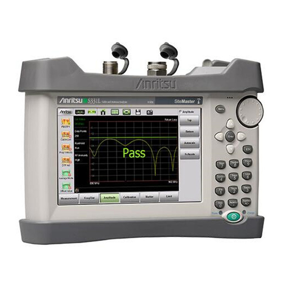
3-2 Common RF Terms Cable and Antenna Measurements 4 Measurement Type 5 Marker 2 (Marker to Valley) 6 Stop Frequency (F2) 7 Pass Message (Active trace is below the limit line in Return Loss measurement) 8 Marker Table 9 Start Frequency 10 Measurement Details (also Menu Shortcuts) 11 User-defined Setup and Menu Shortcuts (not available in Classic mode) - Page 53 Cable and Antenna Measurements 3-2 Common RF Terms Insertion Loss (Cable Loss): Measures the total amount of signal energy absorbed (lost) by the cable assembly. Measured in dB. S21 is another name for this measurement. This is often a pass/fail measurement. Return Loss: Measurement in dB of reflected energy caused by impedance mismatch.
-
Page 54: Overview
3-3 Overview Cable and Antenna Measurements Overview What is Measured? Line sweeping is a quality measure of the transmission lines and/or antenna system. Systems may include cables, connectors, lightning protectors, tower mounted amplifiers, and antennas (Figure 3-2). Line sweeping can measure the power losses in the system at the functional frequencies and measures system impedance and confirms whether the system meets carrier specifications. -
Page 55: Why Measure
Cable and Antenna Measurements 3-3 Overview The Site Master does not measure system linearity (PIM Testing). Anritsu also sells the PIM Master available Note in several carrier bands that does test for passive intermodulation. Why Measure? The basic goal of a wireless communication system is to transfer the... -
Page 56: Line Sweeping
3-3 Overview Cable and Antenna Measurements Line Sweeping System performance issues are seen in two ways: excessive reflections (more common) caused by impedance mismatches or excessive insertion losses (less common) caused by energy dissipated in the connectors or cables. The two measurements used to determine communication system performance are: •... - Page 57 Cable and Antenna Measurements 3-3 Overview 1 Failure at Jumper (1.22 m) 2 Possible Failure at 8.31 m 3 Example of Good Connector (~30 dB) 4 Precision Load Connected at End of Cable (24.65 m) Figure 3-5. Distance to Fault Measurement Shows the Failing Components The second common Line Sweeping measurement is Cable Loss (Figure 3-6 on page...
-
Page 58: Calibration
OPEN, SHORT, and LOAD (OSL), which are sold separately. Alternatively, you can use the internal InstaCal. The external InstaCal Calibration Module is NOT compatible with the Site Master S331L. For Transmission measurements, the external USB sensor itself is used as part of the calibration step, and no additional components are needed. -
Page 59: Line Sweep Measurements
Cable and Antenna Measurements 3-4 Line Sweep Measurements Anritsu recommends allowing the S331L to warm up for 5 minutes to typical operation temperature before calibrating. Note The instrument will require a new OSL calibration if the internal instrument temperature changes more than 20 ºC after calibration. - Page 60 3-4 Line Sweep Measurements Cable and Antenna Measurements Return Loss measures the reflected power of the system in decibels (dB). This measurement can also be taken in the Standing Wave Ratio (SWR) mode, which is the ratio of voltage peaks to voltage valleys caused by reflections.
-
Page 61: Cable Loss Measurement
3. Press the Amplitude main menu key and enter the top and bottom values for the display or press Fullscale. 4. Press the Calibration main menu key and perform a calibration of the instrument. Anritsu suggests using a phase-stable test port cable. See Chapter 7 for details. - Page 62 3. Press the Amplitude main menu key and enter top and bottom values for the display or press Full Scale. 4. Press the Calibration main menu key to start calibration of the instrument. Anritsu suggests using a phase-stable test port cable. Chapter 7 for details.
-
Page 63: Dtf Measurement
Cable and Antenna Measurements 3-4 Line Sweep Measurements DTF Measurement Distance-To-Fault (DTF) measurements are made with the antenna disconnected and replaced with a 50 Ω precision load at the end of the transmission line. This measurement allows analysis of the various components of the transmission feed line system in the DTF mode. - Page 64 Incorrect propagation velocity values affect the distance accuracy, and inaccurate cable attenuation values affect the accuracy of the amplitude values. The Site Master S331L is equipped with a cable list (Freq/Dist > DTF Setup > Cable List) including most of the common cables currently used.
- Page 65 Line Sweep Tools (LST). Instructions for using the LST Cable Editor are available in the software Help menu. The latest version of LST is available from the Anritsu web site: http://www.anritsu.com/. The name, propagation velocity, and cable loss of the selected cable are displayed below the trace window during distance measurements (Measurement >...
- Page 66 3-4 Line Sweep Measurements Cable and Antenna Measurements Distance Resolution Distance resolution is the Site Master’s ability to separate two closely spaced discontinuities. If the resolution is 5 meters and there are two faults 3 meters apart, the Site Master will not be able to show both faults until the resolution is improved by widening the frequency span.
- Page 67 Cable and Antenna Measurements 3-4 Line Sweep Measurements Windowing The theoretical requirement for inverse FFT is for the data to extend from zero frequency to infinity. Side lobes appear around a discontinuity because the spectrum is cut off at a finite frequency. Windowing reduces the side lobes by smoothing out the sharp transitions at the beginning and the end of the frequency sweep.
- Page 68 3-4 Line Sweep Measurements Cable and Antenna Measurements Rectangular Nominal Minimum Figure 3-13. Effects of Windowing on a Sample Trace DMax (Maximum Usable Distance) DMax is the maximum horizontal distance that can be analyzed. The Stop Distance cannot exceed DMax. If the cable is longer than DMax, DMax needs to be improved by increasing the number of data points or lowering the frequency span (ΔF).
- Page 69 Cable and Antenna Measurements 3-4 Line Sweep Measurements 3. Press the Distance submenu key and then select DTF Aid. Use the touchscreen, rotary knob, or Up/Down arrow keys to navigate through all the DTF parameters. a. Highlight a parameter in the DTF Aid table to edit, then press Edit or Enter to display a parameter for editing.
- Page 70 3-4 Line Sweep Measurements Cable and Antenna Measurements Figure 3-14. DTF Return Loss with a Short at the End of the Cable (20.5 m) Figure 3-14, M1 and M2 are jumper cable connections. The Note peak beyond the end of the cable at M3 is the return reflection of the M2 peak.
- Page 71 Cable and Antenna Measurements 3-4 Line Sweep Measurements Figure 3-15. DTF Return Loss Measurement (Antenna at 20.83 m) Figure 3-16. Failing DTF Return Loss Measurement (Load at 20.83 m) S331L UG PN: 10580-00321 Rev. M 3-21...
- Page 72 3-4 Line Sweep Measurements Cable and Antenna Measurements The jumper connector at 17.5 m was found to be loose and dirty. After cleaning and tightening to specification, another DTF measurement showed that the connector now passed the carrier 25 dB specification, indicated by the limit line (Figure 3-17).
- Page 73 Cable and Antenna Measurements 3-4 Line Sweep Measurements Figure 3-18 shows the same system with the antenna reattached. The reflection of the jumper connector in now reduced to 27.64 dB. Figure 3-18. DTF Return Loss Measurement (Antenna at 20.83 m) S331L UG PN: 10580-00321 Rev.
-
Page 74: Advanced Measurements
3-5 Advanced Measurements Cable and Antenna Measurements Advanced Measurements Smith Chart The Smith Chart is a graphical tool for plotting impedance data versus frequency. It converts the measured reflection coefficient data into impedance data and displays it in a manner that makes the Smith Chart a useful tool for determining and tuning input match. - Page 75 Cable and Antenna Measurements 3-5 Advanced Measurements Figure 3-20. Set Reference Impedance for Smith Chart Calculations S331L UG PN: 10580-00321 Rev. M 3-25...
-
Page 76: 1-Port Phase
3-5 Advanced Measurements Cable and Antenna Measurements 1-Port Phase The S331L can display the phase of the reflection measurements at the RF Out/Reflect In port. The Phase display range is from –450 degrees to +450 degrees. The 1-port phase measurement is most useful when making relative measurements (comparing the phase of one device to the phase of another) by utilizing the Trace Math function (Trace –... -
Page 77: Transmission (Ext. Sensor)
Cable and Antenna Measurements 3-5 Advanced Measurements Transmission (Ext. Sensor) To make more accurate cable loss measurements, especially for cables with more than 10 dB of loss, you can use the Transmission measurement with External Sensor. For this measurement, connect the cable under test to the RF Out/Reflect In port of the Site Master, and connect a USB power sensor to the other end of the cable. -
Page 78: Measurement Setup
3-6 Measurement Setup Cable and Antenna Measurements Measurement Setup This section describes how to set up the Cable and Antenna parameters, markers, and limit lines. Frequency Setting up the Measurement Frequency using Start and Stop Frequencies 1. Press the Freq/Dist main menu key then Frequency if the menu is collapsed. -
Page 79: Sweep
Cable and Antenna Measurements 3-6 Measurement Setup Setting the Amplitude using Autoscale With Autoscale, the instrument will automatically set the top and bottom scales to display the current measurement. 1. Press the Amplitude main menu key. 2. Press the Autoscale submenu key. Setting the Amplitude using Fullscale With Fullscale, the instrument will automatically set the top and bottom scales to the default values based on the measurement type. - Page 80 3-6 Measurement Setup Cable and Antenna Measurements Run/Hold This key is used to start and stop line sweeping. When the Sweep Type is set to Single mode, this key triggers a single sweep. 1. Press the Sweep (3) menu key. 2.
-
Page 81: Limit Lines
Cable and Antenna Measurements 3-6 Measurement Setup Limit Lines Limit lines are used for visual reference or for pass/fail criteria using the limit alarm and pass/fail message settings. Pressing either the Limit (6) key or the Limit main menu key displays the Limit menu. Overview of limit lines: •... - Page 82 3-6 Measurement Setup Cable and Antenna Measurements 4. Tap on a limit line segment, then choose to Add, Edit, or Delete the segment. For editing purposes, consider a single, full-span limit line as a single segment. Press the Close submenu key or the ESC key to close the Segments submenu and return to the Limit menu.
- Page 83 Cable and Antenna Measurements 3-6 Measurement Setup When editing a segmented limit line, a table is displayed with each segment in a separate row (Figure 3-24). The type is displayed as U or L. The Start and Stop settings are displayed as Start(x1,y1) and Stop(x2,y2).
- Page 84 3-6 Measurement Setup Cable and Antenna Measurements Figure 3-26 shows a sequence of creating limit line segments for a filter measurement. Figure 3-26. Creating Limit Line Segments 3-34 PN: 10580-00321 Rev. M S331L UG...
- Page 85 Cable and Antenna Measurements 3-6 Measurement Setup Figure 3-27 shows the result of moving limit line segments. Note that when moving upper or lower segments, all segments of the same type will be moved by the same amplitude value, meaning all upper or lower segments will move simultaneously.
- Page 86 3-6 Measurement Setup Cable and Antenna Measurements Pass/Fail Messages When set to On, a message is displayed. Fail is displayed Pass Fail when the trace crosses or touches a limit line, as illustrated in Figure 3-28. Note that Upper(U) or Lower (L) or both (U, L) are displayed.
-
Page 87: Markers
Cable and Antenna Measurements 3-6 Measurement Setup Markers Markers can be applied to active or recalled measurements. The instrument supports eight markers. Marker information is stored in measurement and setup files and is displayed when either file type is recalled. Pressing the Marker main menu key will bring up the marker functions. - Page 88 3-6 Measurement Setup Cable and Antenna Measurements Figure 3-29. Markers 1, 2, and 5 are Out of Range Select, Activate, and Place a Marker / Delta Marker 1. Press the Marker main menu key. One of the markers is automatically selected. Select a different marker with the Select(1-8) button.
- Page 89 Cable and Antenna Measurements 3-6 Measurement Setup Marker Table The Marker Table displays below the sweep window. The table is automatically sized to display all markers that are turned on. The table displays marker frequency/distance, amplitude and delta information for delta markers. To display the marker table: 1.
- Page 90 3-6 Measurement Setup Cable and Antenna Measurements Figure 3-31. Marker Search, Marker 1 Set to Peak Peak Between Markers Another marker search option is to select the peak or valley between two Markers instead of the entire displayed frequency or distance span. Markers 5 and 7 can be used to find the peak or valley between Marker 1 and Marker 2.
- Page 91 Cable and Antenna Measurements 3-6 Measurement Setup Figure 3-32. Bounded Marker Search Searching for peaks or valleys turns on any required markers Note and place them in the default locations. Tracking Markers A tracking marker is set to a peak or to a valley. As the peak (or valley) varies in the measurement trace, the tracking marker stays at the peak (or valley).
- Page 92 3-6 Measurement Setup Cable and Antenna Measurements Figure 3-33, Marker M1 is set for Tracking a Valley. The three images show how the marker remains at the valley as the measurement trace changes. Figure 3-33. Tracking Marker Set to Valley 3-42 PN: 10580-00321 Rev.
- Page 93 Cable and Antenna Measurements 3-6 Measurement Setup Figure 3-34, Marker M5 is set for Tracking a Valley between markers M1 and M2. Marker M6 is Tracking a Valley between markers M3 and M4. The table of markers (below the sweep window in Figure 3-34) shows only 4 markers, but the table can be expanded or reduced by...
-
Page 94: Trace
Cable and Antenna Measurements Trace The Site Master S331L allows the user to concurrently view the live trace and a second trace that is stored in trace memory. The user can compare the two traces visually or using trace math functions. Pressing the Trace (5) main menu key will bring up the trace functions. - Page 95 Cable and Antenna Measurements 3-7 Trace From the Trace menu, users can Copy Trace to Display Memory. The copied trace can be displayed on the Site Master and used for trace math. Trace Display allows viewing of two traces at the same time to compare the trace stored in memory to the live trace.
- Page 96 3-7 Trace Cable and Antenna Measurements Trace Math Example The example below illustrates how the trace math features can be used to compare the phase of two cables. 1. Complete the steps described in “Trace Overlay” on page 3-45. 2. Press Trace Math and select Trace - Mem , Trace + Mem, or (Figure 3-37).
- Page 97 Cable and Antenna Measurements 3-7 Trace The trace math functions often seem backwards to new users. The points to remember with Trace - Memory, Trace + Memory, and (Trc + Mem) / 2 are: Notes • The numbers on the y-axis are negative. •...
- Page 98 3-7 Trace Cable and Antenna Measurements Table 3-1. Trace Math Details (2 of 2) Example from Figure 3-37 Example Description (Trace + Memory) / 2 In the (Trace + Memory) / 2 graph the yellow trace (not shown) is the result of adding the purple trace to the active trace and then dividing the result by 2.
-
Page 99: Measurement Review
Cable and Antenna Measurements 3-8 Measurement Review Measurement Review Table 3-2 provides a summary of the typical measurements and required cable end tool. The typical values are for general information purposes. The carriers will provide final values in the acceptance testing specification. -
Page 100: C&A Menus
3-9 C&A Menus Cable and Antenna Measurements C&A Menus Figure 3-38 Figure 3-39 show the map of the Cable and Antenna Analyzer menus. The following sections describe main menus and associated submenus. The submenus are listed in the order they appear on the display from top to bottom under each main menu. - Page 101 Cable and Antenna Measurements 3-9 C&A Menus Sweep ScrnShot Limit AutoScl See Limit Menu Refer to Chapter 9 See Amplitude Menu Sweep Setup Sweep Setup Data Points Data Points Run/Hold Save Trace Run/Hold Run/Hold /H ld See Sweep Menu Hold Hold Refer to Chapter 8 Trace...
-
Page 102: Measurement Menu
3-10 Measurement Menu Cable and Antenna Measurements 3-10 Measurement Menu Key Sequence: Measurement Standard: Measurement Return Loss: Return Loss is used to characterize RF components and systems. The Return Loss indicates how well the system is matched by taking the ratio of Standard Standa the reflected signal to the incident signal, and... - Page 103 Cable and Antenna Measurements 3-10 Measurement Menu Measurement Menu (Continued) Advanced: Smith Chart: Press this submenu key to view the Measurement measurement results in a Smith Chart. The Smith Chart is a graphical tool that is used to plot the impedance of Standard Standa the device connected to the Site Master.
-
Page 104: Freq/Dist Menu
3-11 Freq/Dist Menu Cable and Antenna Measurements 3-11 Freq/Dist Menu Key Sequence: Freq/Dist Frequency: Freq/Dist Start Frequency (F1): Press the Start Frequency (F1) submenu key and enter the desired frequency using the Up/Down arrow keys, the rotary knob, or the Frequency keypad. -
Page 105: Freq/Dist Menu (Continued)
Cable and Antenna Measurements 3-11 Freq/Dist Menu Freq/Dist Menu (Continued) Key Sequence: Freq/Dist DTF Setup: DTF Setup Cable List: The Cable List submenu key opens a list of available cable specifications (Figure 3-11). Using Cable List Up/Down arrow keys, the rotary knob, or the touchscreen, select the desired cable and press Enter. -
Page 106: Windowing Menu
3-11 Freq/Dist Menu Cable and Antenna Measurements Windowing Menu Key Sequence: Freq/Dist > DTF Setup > Windowing Rectangular: Rectangular Windowing shows the highest side lobe levels (worst) and the greatest main Freq/Dist lobe resolution (best). Nominal Side Lobe: Nominal Side Lobe Windowing Windowing shows less side lobe levels than Rectangular Windowing (good) but lower main lobe resolution... -
Page 107: Amplitude Menu
Cable and Antenna Measurements 3-12 Amplitude Menu 3-12 Amplitude Menu Key Sequence: Amplitude Top: Sets the top amplitude value using the keypad, the arrow keys, or the rotary knob. Press Enter to Amplitude complete the entry. Bottom: Sets the bottom amplitude value using the Amplitude keypad, the arrow keys, or the rotary knob. - Page 108 3-12 Amplitude Menu Cable and Antenna Measurements Figure 3-46. Set Reference Impedance for Smith Chart Measurement 3-58 PN: 10580-00321 Rev. M S331L UG...
-
Page 109: Calibration Menu
Cable and Antenna Measurements 3-13 Calibration Menu 3-13 Calibration Menu Key Sequence: Calibration Start Calibration: Opens the Calibration dialog box. Refer to Chapter 7, “Calibration” for detailed Calibration information. Cal Info: Displays the Calibration Information table Calibration showing the current and active calibration settings. Cal Correction: Turn Cal Correction On to apply Start Start... -
Page 110: Marker Menu
3-14 Marker Menu Cable and Antenna Measurements 3-14 Marker Menu Key Sequence: Marker Marker Setup: Marker Select (1-8) M#: Press to turn on a marker (1 to 8) and selects which marker is active (green half circle). Current active marker is displayed on the button (M1). Marker Setup Edit: Press to change the position of the active marker using the Up/Down arrow keys, rotary knob or the... -
Page 111: Marker Menu (Continued)
Cable and Antenna Measurements 3-14 Marker Menu Marker Menu (Continued) Key Sequence: Marker Marker Search: Marker Search Tracking (On Off): When turned On, the active marker becomes a tracking marker and defaults to Tracking Tracking tracking the peak. To track Valleys, press the Marker to Valley button after turning on Tracking. -
Page 112: Limit Menu
3-15 Limit Menu Cable and Antenna Measurements 3-15 Limit Menu Limit lines can be used for visual reference only, or for pass/fail criteria using the limit alarm and Pass/Fail Message keys. Limit alarm failures are reported whenever a signal crosses the limit line. Key Sequence: Limit (6) or Limit Limit Active Limit (Upper Lower): This key toggles the... -
Page 113: Limit Menu (Continued)
Cable and Antenna Measurements 3-15 Limit Menu Limit Menu (Continued) Key Sequence: Limit > Limit State Limit State Limit State Limit St Off: The limit line state is set to off. Single: The limit line state is set to on and the limit line type is set to single. -
Page 114: Sweep Menu
3-16 Sweep Menu Cable and Antenna Measurements 3-16 Sweep Menu Key Sequence: Sweep (3) Data Points: Sets the number of data points: 130, Sweep 259, 517, 1033 or 2065. Run/Hold: Toggles between Run and Hold. When in Hold mode, pressing this key starts the sweeping and Sweep Setup provides a trigger. -
Page 115: Trace Menu
Cable and Antenna Measurements 3-17 Trace Menu 3-17 Trace Menu Key Sequence: Trace (5) Trace: Trace Copy Trace to Display Memory: Copies the current trace display to memory for use in Trace Math and Trace Display options. Trace Trace Display: Press to change the display Copy Trace To options. -
Page 116: Other Menus Keys
3-18 Other Menus Keys Cable and Antenna Measurements 3-18 Other Menus Keys Refer to Table 2-1, “Site Master Keypad Functions” on page 2-10. 3-66 PN: 10580-00321 Rev. M S331L UG... -
Page 117: Chapter 4-Classic Mode Operation
Chapter 4 — Classic Mode Operation Introduction The Site Master S331L features a Classic Cable and Antenna Analyzer measurement mode, which allows users of Site Master legacy series (up to series D) to become efficient immediately. To provide quick and easy... - Page 118 4-1 Introduction Classic Mode Operation “Classic” Mode (Chapter 4) “Classic” Mode (Chapter 4) “Advanced” Mode (Chapter 3) Figure 4-1. Display Appearance in Classic Mode vs. Advanced Mode PN: 10580-00321 Rev. M S331L UG...
- Page 119 Classic Mode Operation 4-1 Introduction Descriptions of the main menus and associated submenus that are common between the Classic and Advanced measurement modes are provided in Chapter 3 Figure 3-40 through Figure 3-54. Table 4-1. Menu Differences Between Classic Mode and Advanced Mode Advanced S331L Cable and Antenna Classic Mode...
- Page 120 4-1 Introduction Classic Mode Operation Figure 4-2 Figure 4-3 show an overview of the Classic Cable and Antenna Analyzer menus. Mode Freq/Dist Amplitude Calibration Marker Meas/Disp Meas/Disp Amplitude Calibration Marker Freq - SWR Frequency Start Start Data Points a Points Calibration a a l l bration...
- Page 121 Classic Mode Operation 4-1 Introduction Sweep ScrnShot Limit AutoScl See Amplitude Menu Refer to Chapter 9 Meas/Disp Single Limit Limit Line Limit Line Data Points a Points Run/Hold Trace Run/Hold n/Hold Edit Value See Meas/Disp Menu Hold Hold Trace Sweep Type Sweep Type Limit Alarm Limit Alarm...
-
Page 122: Marker Menu
4-2 Marker Menu Classic Mode Operation Marker Menu Key Sequence: Marker Marker After pressing the Marker button, Marker 1 (M1) is Marker automatically turned ON and appears at the last used location. If there is no last used location (after a preset, for example), Marker 1 will appear in the center of the Marker Marker... -
Page 123: Marker Menu (Continued)
Classic Mode Operation 4-2 Marker Menu Marker Menu (Continued) Key Sequence: Marker > M 1 Marker Marker 1 Marker 1 M 1 (On Off): Press this key to turn OFF the selected marker (M1 to M6). Edit: Press this key to enter a marker value. Edit Type (Ref Delta): Press this key to toggle the marker type between Reference and Delta. -
Page 124: Limit Menu
4-3 Limit Menu Classic Mode Operation Limit Menu Limit lines can be used for visual reference only, or for pass/fail criteria using the limit alarm and Pass/Fail Message keys. Limit alarm failures are reported whenever a signal crosses the limit line. Key Sequence: Limit (6) Single Limit Limit Line: This key toggles the limit line on or off. - Page 125 Classic Mode Operation 4-3 Limit Menu Table 4-2. Limit Lines Messages Typical End Measurement Tool Pass/Fail Criteria Return Loss Load Pass when the trace is below the limit line DTF Return Loss Load Pass when the trace is below the limit line Cable Loss Short or Open Pass when the trace is above the limit line...
- Page 126 4-3 Limit Menu Classic Mode Operation 4-10 PN: 10580-00321 Rev. M S331L UG...
-
Page 127: Chapter 5-Internal Power Meter
Chapter 5 — Internal Power Meter Overview This chapter provides an overview of power meter measurements and how to set up the instrument to use the power meter. The power meter displays measured input power at the power meter connector in dBm and Watts or relative power in dB and percentage. -
Page 128: Introduction
5-2 Introduction Internal Power Meter Introduction Figure 5-1 illustrates the preset Power Meter display with limits turned on and no source power. 1 Preset -90 dBm Lower Limit 2 Blue Ticks Indicate Approximate Power Meter Range 3 Power Meter Mode 4 Preset 90 dBm Upper Limit 5 Current Power in dBm and Watts (including any Offset Value) or “No Signal Detected”... -
Page 129: General Measurement Setup
Internal Power Meter 5-3 General Measurement Setup General Measurement Setup Maximum power level to the Site Master S331L Power Meter Warning connector without causing damage is 27 dBm. Connection and Offset 1. Connect the source to be measured to the power meter connector. - Page 130 5-3 General Measurement Setup Internal Power Meter Press the Autoscale submenu key to adjust the range automatically. The current power level will be centered with Min Value automatically set at 90% of the current power and Max Value automatically set at 110% of the current power. Refer Figure 5-2.
-
Page 131: Changing The Display Units
Internal Power Meter 5-3 General Measurement Setup Changing the Display Units The power meter scale can be displayed in dBm or Watts. Use the following procedure to change the displayed units: 1. Press the Amplitude main menu key. 2. Press the Units submenu key and select the display units. Displaying Relative Power Use the following procedure to select Relative Power through the Amplitude menu. - Page 132 5-3 General Measurement Setup Internal Power Meter Relative First Power Level in dBm and mW First Power Level, Relative On Reduced Second Power Level, -6 dB (25%) of First Figure 5-3. Relative Power Example Relative power is displayed numerically in dB and Note percentage, scale is absolute.
-
Page 133: Setting Upper And Lower Limits
Internal Power Meter 5-3 General Measurement Setup Setting Upper and Lower Limits Maximum and minimum limits can be set as follows: 1. Press the Limit main menu key and set Limit to On. 2. Press the Upper Value submenu key and use the keypad, Up/Down arrow keys, or the rotary knob to set the desired upper limit. - Page 134 5-3 General Measurement Setup Internal Power Meter Limits Turned Off (Yellow Needle, White Text) Power Level Within Limits (Green Text and Needle) Power Level Beyond Limits (Red Text and Needle) Figure 5-4. Limit Setting Display Changes PN: 10580-00321 Rev. M S331L UG...
-
Page 135: Average Menu Options
Internal Power Meter 5-3 General Measurement Setup Average Menu Options If the displayed values are unstable increase the Running Average from the default value of 1. Maximum value is 60. Increasing the running average is useful when measuring unstable sources or when measuring near the zero calibration level described below. - Page 136 5-3 General Measurement Setup Internal Power Meter 4. Turn on the RF source of the Device Under Test or connect the source from the test apparatus. The power meter will now display the power level with the unwanted interference signal subtracted out.
-
Page 137: Power Meter Menus
Internal Power Meter 5-4 Power Meter Menus Power Meter Menus Figure 5-6 shows the map of the Power Meter menus. The following sections describe main menus and associated submenus. The submenus are listed in the order they appear on the display from top to bottom under each main menu. -
Page 138: Frequency Menu
5-5 Frequency Menu Internal Power Meter Frequency Menu Key Sequence: Frequency Measurement Frequency: Sets the frequency at the Frequency center of the measurement. Frequencies can be entered using the keypad and then selecting a unit (GHz, MHz, kHz, or Hz) submenu key or by using the Frequency rotary knob, or the Up/Down arrow keys and pressing Enter to set the frequency, or Esc to restore the... -
Page 139: Calibration Menu
Internal Power Meter 5-7 Calibration Menu Calibration Menu Key Sequence: Calibration Zero On Off: Toggles the zero calibration On or Off to remove noise or interference power. Refer to Calibration “Calibration” on page 5-9 for additional information. Calibration Zero Zero Figure 5-9. -
Page 140: Limit Menu
5-9 Limit Menu Internal Power Meter Limit Menu Key Sequence: Limit or Limit (6) Limit: Turns the limits On or Off. Limit Upper Value: Sets the upper limit (displayed as red hash marks). Enter the desired number by using the keypad, the rotary knob, or the Up/Down arrow keys. -
Page 141: Chapter 6-High Accuracy Power Meter
Chapter 6 — High Accuracy Power Meter Overview This chapter provides an overview of power meter measurements and how to set up the instrument to use an external USB Sensor in the High Accuracy Power Meter mode. Actual power is measured at the USB sensor connector in dBm and Watts or relative power in dB and percentage. -
Page 142: Introduction
6-2 Introduction High Accuracy Power Meter Introduction Figure 6-1 illustrates the preset Power Meter display with limits turned on and no source power. 1 Preset -90 dBm Lower Limit 2 Power Meter Needle 3 High Accuracy Power Meter Mode and Connected USB Sensor 4 Preset 90 dBm Upper Limit 5 Current Power in dBm and Watts (including any Offset Value) or “No USB sensor detected”... -
Page 143: General Measurement Setup
High Accuracy Power Meter 6-3 General Measurement Setup General Measurement Setup Refer to the label on the USB sensor for information on Note frequency range and dynamic range. Connection RF IN Connection Setup for PSN50, S331AL SiteMaster Menu MA24106A/08/18A/26A Enter Preset System Save... -
Page 144: Connection And Offset
6-3 General Measurement Setup High Accuracy Power Meter Connection and Offset 1. Connect the source to be measured to the USB sensor. Use any required external attenuation or gain so the expected power level is within specification for the sensor. 2. - Page 145 High Accuracy Power Meter 6-3 General Measurement Setup Before Autoscale After Autoscale Figure 6-3. Autoscale to Zoom In on a Measurement S331L UG PN: 10580-00321 Rev. M...
-
Page 146: Changing The Display Units
6-3 General Measurement Setup High Accuracy Power Meter Changing the Display Units The power meter scale can be displayed in dBm or Watts. Use the following procedure to change the displayed units: 1. Press the Amplitude main menu key. 2. Press the Units submenu key and select the display units. Displaying Relative Power Use the following procedure to select Relative Power through the Amplitude menu. - Page 147 High Accuracy Power Meter 6-3 General Measurement Setup Relative First Power Level in dBm and mW First Power Level, Relative On Reduced Second Power Level, -6 dB (25%) of First Figure 6-4. Relative Power Example Relative power is displayed numerically in dB and Note percentage, scale is absolute.
-
Page 148: Setting Upper And Lower Limits
6-3 General Measurement Setup High Accuracy Power Meter Setting Upper and Lower Limits Maximum and minimum limits can be set as follows: 1. Press the Limit main menu key and set Limit to On. 2. Press the Upper Value submenu key and use the keypad, Up/Down arrow keys, or the rotary knob to set the desired upper limit. - Page 149 High Accuracy Power Meter 6-3 General Measurement Setup Limits Turned Off (Yellow Needle, White Text) Power Level Within Limits (Green Text and Needle) Power Level Beyond Limits (Red Text and Needle) Figure 6-5. Limit Setting Display Changes S331L UG PN: 10580-00321 Rev. M...
-
Page 150: Average Menu Options
6-3 General Measurement Setup High Accuracy Power Meter Average Menu Options If the displayed values are unstable increase the Running Average from the default value of 1. Maximum value is 60. Increasing the running average is useful when measuring unstable sources or when measuring near the zero calibration level described below. -
Page 151: Zero Failure
High Accuracy Power Meter 6-3 General Measurement Setup Zero Failure This message appears if the zero operation is unsuccessful. The reason could be the presence of RF power at the input of the sensor. Turn off the RF input to the sensor or disconnect the sensor from the RF source and try the zero operation again. -
Page 152: Ma24105A Inline Power Sensor
6-4 MA24105A Inline Power Sensor High Accuracy Power Meter MA24105A Inline Power Sensor Refer to the previous sections in this chapter for a general overview of using USB sensors with the Site Master. This section is specific to the additional options and settings Note available when the MA24105A in-line sensor is attached (Figure 6-2 on page... -
Page 153: In-Line Sensor Setup
High Accuracy Power Meter 6-4 MA24105A Inline Power Sensor Figure 6-7. Summary Table View In-Line Sensor Setup The Sensor Settings submenu under the Display main menu adjusts the in-line sensor parameters (Figure 6-8). The on screen instructions provide information for each parameter. To change a parameter, select it with the Up/Down arrows or the touchscreen and press Edit. - Page 154 6-4 MA24105A Inline Power Sensor High Accuracy Power Meter Figure 6-8. Sensor Settings Modulation In the Sensor Settings dialog, highlight the Modulation = ... row and press Edit. Use the Up/Down keys, rotary knob or touchscreen to highlight the desired modulation type, and then press Select. Figure 6-9.
- Page 155 High Accuracy Power Meter 6-4 MA24105A Inline Power Sensor Duty Cycle Sets the duty cycle used for averaging when the forward measurement is set to Burst Average Manual. Select a value from 0% to 100%. In the Sensor Settings dialog, highlight the Duty Cycle = ... row and press Edit. Use the Up/Down keys, rotary knob or key pad to set the duty cycle and then press Enter.
- Page 156 6-4 MA24105A Inline Power Sensor High Accuracy Power Meter CCDF Threshold Sets the power threshold value used in the Complementary Cumulative Distribution Function (CCDF) forward measurement. CCDF describes the probability that the signal power is greater than the user-define threshold value. In the Sensor Settings dialog, highlight the CCDF Threshold ...
-
Page 157: Displayed Measurements
High Accuracy Power Meter 6-4 MA24105A Inline Power Sensor Displayed Measurements Select the forward and reverse measurements to display in the graph area (the analog graph always shows the forward measurement). Select Forward Display and/or Reverse Display under the Display main menu and choose a measurement. -
Page 158: Summary View
6-4 MA24105A Inline Power Sensor High Accuracy Power Meter Summary View The Summary Table button under the Display main menu provides a summary of Site Master instrument settings, DUT forward and reverse measurements, and sensor settings (Figure 6-12). Figure 6-12. Summary Table Modifying sensor settings is described in “In-Line Sensor Note... -
Page 159: Displaying Relative Power
High Accuracy Power Meter 6-4 MA24105A Inline Power Sensor Displaying Relative Power Use the following procedure to select Relative Power through the Amplitude menu. 1. With the desired base power (reference) levels connected to the USB in-line sensor, press the Amplitude main menu key. 2. -
Page 160: Limits For Forward And Reverse Measurements
6-4 MA24105A Inline Power Sensor High Accuracy Power Meter Limits for Forward and Reverse Measurements Connecting the MA24105 sensors enhances the limit menu by providing upper and lower limits for both forward and reverse measurements. 1. Press the Limit main menu key and set Limit to On. 2. -
Page 161: High Accuracy Menus
High Accuracy Power Meter 6-5 High Accuracy Menus High Accuracy Menus Figure 6-15 shows the map of the High Accuracy Power Meter menus. The following sections describe main menus and associated submenus. The submenus are listed in the order they appear on the display from top to bottom under each main menu. -
Page 162: Frequency Menu
6-6 Frequency Menu High Accuracy Power Meter Frequency Menu Key Sequence: Frequency Measurement Frequency: Sets the frequency at the Frequency center of the measurement. Frequencies can be entered using the keypad and then selecting a unit (GHz, MHz, kHz, or Hz) submenu key or by using the Frequency rotary knob, or the Up/Down arrow keys and pressing Enter to set the frequency, or Esc to restore the... -
Page 163: Calibration Menu
High Accuracy Power Meter 6-8 Calibration Menu Calibration Menu Key Sequence: Calibration Zero Sensor: Initiates the zero calibration of the sensor. A message box is displayed with further Calibration instructions. Refer to “Calibration” on page 6-10 additional information. Calibration Zero Sensor Figure 6-18. -
Page 164: Limit Menu
6-10 Limit Menu High Accuracy Power Meter 6-10 Limit Menu Key Sequence: Limit or Limit (6) Limit: Turns the limits On or Off. Limit Upper Value: Sets the upper limit (displayed as red hash marks). Enter the desired number by using the keypad, the rotary knob, or the Up/Down arrow keys. -
Page 165: Ma24105A Menus
High Accuracy Power Meter 6-11 MA24105A Menus 6-11 MA24105A Menus Figure 6-15 shows the map of the High Accuracy Power Meter menus when the MA24105A sensor is attached to the Site Master. The following sections describe main menus and associated submenus. The submenus are listed in the order they appear on the display from top to bottom under each main menu. -
Page 166: Display Setup Menu
6-12 Display Setup Menu High Accuracy Power Meter 6-12 Display Setup Menu Key Sequence: Display Setup Sensor Settings: Displays the Forward Settings table Display Setup (Figure 6-8) for the MA24105A sensor. Select a sensor parameter using the Up/Down arrow keys or the touchscreen. -
Page 167: Forward Menu
High Accuracy Power Meter 6-12 Display Setup Menu Forward Menu Key Sequence: Display Setup > Forward Average Power: Press this submenu key to have the sensor measure the average power in the forward Display Setup direction. Crest Factor: Press this submenu key to have the Forward Forwar sensor measure the Crest Factor in the forward... -
Page 168: Reverse Menu
6-12 Display Setup Menu High Accuracy Power Meter Reverse Menu Key Sequence: Display Setup > Reverse Average Power: Press this submenu key to have the sensor measure the average power in the reverse Display Setup direction. Reflection Coefficient: Press this submenu key to Reverse Reverse measure the reflection coefficient:... -
Page 169: Frequency Menu
High Accuracy Power Meter 6-13 Frequency Menu 6-13 Frequency Menu Key Sequence: Frequency Measurement Frequency: Sets the frequency at the center of the measurement. Frequencies can be Frequency entered using the keypad and then selecting a unit (GHz, MHz, kHz, or Hz) submenu key or by using the rotary knob, or the Up/Down arrow keys and pressing Frequency Enter to set the frequency, or Esc to restore the... -
Page 170: Amplitude Menu
6-14 Amplitude Menu High Accuracy Power Meter 6-14 Amplitude Menu Key Sequence: Amplitude Amplitude: Amplitude Max Value: Sets the maximum value on the display in dBm or Watts. Min Value: Sets the minimum value on the display in Amplitude dBm or Watts. Autoscale: Adjusts the Top and Bottom values so that Max Value the power meter needle will be shown in the middle of... -
Page 171: Calibration Menu
High Accuracy Power Meter 6-15 Calibration Menu 6-15 Calibration Menu Key Sequence: Calibration Zero Sensor: Initiates the zero calibration of the sensor. A message box is displayed with further Calibration instructions. Refer to “Calibration” on page 6-10 additional information. Calibration Zero Sensor Figure 6-27. -
Page 172: Limit Menu
6-17 Limit Menu High Accuracy Power Meter 6-17 Limit Menu Key Sequence: Limit or Limit (6) Limit: Turns the limits On or Off. Limit Fwd Upper Value: Sets the forward measurement upper limit (displayed as red hash marks). Enter the desired number by using the keypad, the rotary knob, Limit or the Up/Down arrow keys. -
Page 173: Trace Menu
High Accuracy Power Meter 6-19 Trace Menu 6-19 Trace Menu This menu is not available in High Accuracy Power Meter measurement mode. 6-20 Other Menus Keys Refer to Table 2-1, “Site Master Keypad Functions” on page 2-10. S331L UG PN: 10580-00321 Rev. M 6-33... - Page 174 6-20 Other Menus Keys High Accuracy Power Meter 6-34 PN: 10580-00321 Rev. M S331L UG...
-
Page 175: Chapter 7-Calibration
Anritsu recommends connecting a phase-stable test port cable (3 meters maximum length) to the RF Out/Reflect In connector and calibrating at the open end of the cable using the Site Master S331L internal InstaCal or external OSL components. Calibrating at the end of the test port cable will remove ripple and loss associated with the cable. - Page 176 7-1 Introduction Calibration Before Calibration After Calibration Figure 7-1. Comparison of Test Port Cable Before and After Calibration PN: 10580-00321 Rev. M S331L UG...
-
Page 177: Calibration Methods
Calibration 7-2 Calibration Methods Calibration Methods For accurate results, the instrument must be calibrated before Note making any measurements. The instrument must be re-calibrated whenever the internal instrument temperature exceeds the calibration temperature window (±20 ºC) or when the test port extension cable is removed or replaced. Unless the calibration type is Flex Cal, the instrument must also be re-calibrated every time the frequency range changes. - Page 178 7-2 Calibration Methods Calibration While OSL Cal tee, InstaCal, or Tranmission (Ext. Sensor) provide alternatives for the tools needed to perform the calibration, Standard Cal or Flex Cal determines the calibration frequency range. The default standard calibration is for a selected frequency range, and is no longer valid if the frequency is changed.
-
Page 179: Calibration Procedures
Calibration 7-3 Calibration Procedures Calibration Procedures In Cable and Antenna Analyzer Mode, calibration is required when the “Cal Status Off” or “Cal Status X” message is displayed or when the test port cable has been changed. The following sections detail how to perform OSL and InstaCal calibration. -
Page 180: Cal Info
7-3 Calibration Procedures Calibration Figure 7-2. Calibration Setup OSL Cal Cal Info From the Calibration main menu, press Cal Info to review the Active Cal Settings and a summary of the current instrument settings (Figure 7-3). Press ESC to close. Figure 7-3. -
Page 181: Temperature Window
The calibration coefficients are saved and can be reapplied by setting Cal Correction back to On. Temperature Window Anritsu recommends allowing the instrument to warm up for ~10 minutes to typical operating temperature before calibrating. Any applied calibration factor will automatically be turned off if the internal temperature moves outside the valid cal window. -
Page 182: Instacal Module Verification
7-4 InstaCal Module Verification Calibration InstaCal Module Verification InstaCal module verification identifies any failures in the module due to circuitry damage or failure of the control circuitry. This test does not attempt to characterize the InstaCal module, which is performed at the factory or the service center. -
Page 183: Calibrate Menu
Calibration 7-5 Calibrate Menu Calibrate Menu Key Sequence: Calibration Start Calibration: Press this submenu key and follow the instruction on screen. Calibration Measure: Starts the calibration process. Cal Method: Select one of the choices Calibration presented – OSL, InstaCal, Transmission (Ext. Sensor), or OSL + Transmission (Ext. - Page 184 7-5 Calibrate Menu Calibration 7-10 PN: 10580-00321 Rev. M S331L UG...
-
Page 185: Chapter 8-File Management
Chapter 8 — File Management Introduction This chapter reviews the file management features of the Site Master S331L. The File menu and associated submenus allow you to save, recall, rename, copy, and delete files in internal memory or on an external USB drive. -
Page 186: File Types
8-3 File Types File Management File Types File name extensions used in the Site Master S331L include: *.dat for Cable and Antenna measurement files *.pm for Power Meter measurement files *.hipm for High Accuracy Power Meter measurement files *.ett for easyTest files *.stp for Setup files... -
Page 187: File Name
File Management 8-4 Save File 1 File name edit box 2 Recent file names (tap to view) 3 Close dialog box (without saving) 4 Press Save to save the file and close the dialog box. Press Esc or the Close button (item 3 above) to cancel. 5 Delete or Backspace key (applies to file name field) 6 EZ Name Keys 7 Digits and symbols keyboard... - Page 188 8-4 Save File File Management To enter a custom file name, simply type over the default name. Optionally, you can use the EZ Name keyboards to quickly enter character strings that make up a custom file name. EZ Name Keyboards Some carriers may require files to be named according to specific conventions, including site ID, color coding, measurement type, termination device, and frequency information.
- Page 189 File Management 8-4 Save File The Separator keys determine whether to automatically insert a separating character (hyphen or underscore) after each name string entered by pressing an EZ Name key. EZ Name Keys Pressing an EZ Name key inserts the associated character string into the name of the file being saved.
-
Page 190: File Type
8-4 Save File File Management User-defined EZ Name keys are saved until a Master Reset is performed or you delete custom files with Preset (9) > Reset Note > Delete Custom Files > Keyboard EZ Names. Refer to the “Preset Menu” on page 9-23 for additional information. -
Page 191: Save Location
File Management 8-4 Save File Save Location The current save destination is shown on the Location button in the Save dialog box. To change to another location, press the Location button and select where to save the file. Double-tap a folder to open it. Figure 8-6. -
Page 192: Recall File
8-5 Recall File File Management Recall File You can recall a previously saved measurement or setup or a screen shot file either from the instrument internal memory or from a removable USB drive. Only one file of any type can be recalled at a time. Recalling a measurement or setup may change the current Note instrument settings and turn off any calibration correction. - Page 193 File Management 8-5 Recall File 5. In the preview screen that opens, press Enter to complete recalling the measurement. To cancel the recall and return to the File Recall menu, press ESC. Figure 8-9. Preview of a Recalled Measurement Figure 8-10 illustrates a recalled measurement and active trace.
-
Page 194: Recall A Setup
8-5 Recall File File Management The recalled measurement is the purple trace and is overlaid on the current active (yellow) trace. In Figure 8-10, the recalled measurement is used to compare the cable loss of two different RF cables. Recalled measurements are automatically saved to trace memory for use in trace match functions. - Page 195 File Management 8-5 Recall File In the example below, the selected file is located in the default ScrnShots folder in the instrument internal memory. Figure 8-11. Screen Shot Selected for Recall 6. A preview screen displaying the selected screen shot is illustrated Figure 8-12.
-
Page 196: Recall A Vip Measurement (Vip Mode Only)
8-5 Recall File File Management Recall a VIP Measurement (VIP Mode Only) In Video Inspection Probe mode, press the Save/Recall main menu key, then press Recall. Confirm that the Filetype is Measurement or All. See Figure 8-13. Figure 8-13. Recall File Type (VIP Mode) Select the file (.vipi extension) with the touchscreen, rotary knob, or the Up/Down arrow keys, then press Enter (or the Recall submenu key). -
Page 197: Recall A Vip Image (Vip Mode Only)
File Management 8-5 Recall File Recall a VIP Image (VIP Mode Only) In VIP mode, press the Save/Recall main menu key, then press Recall. Confirm that the Filetype is VIP Image or All. Select the file (.png extension) with the touchscreen, rotary knob, or the Up/Down arrow keys, then press Enter (or the Recall submenu key). -
Page 198: Rename File
8-6 Rename File File Management Rename File 1. Press the File (1) key to display the File menu. 2. Press File Mgmnt to open the File Mgmnt dialog box. 3. Navigate to the file you wish to rename and press to select. File selected for renaming Figure 8-16. -
Page 199: Copy And Paste File
Figure 8-18. Renamed File Copy and Paste File The Site Master S331L allows multiple files and folders to be copied or moved at the same time. The example below describes how to copy or move files and folders from internal memory to a removable USB drive. - Page 200 8-7 Copy and Paste File File Management You can select a single or multiple files and folders, as illustrated Figure 8-19. Press the top checkbox to select all files and folders in the current directory. Figure 8-19. Multiple Item Selection 4.
- Page 201 File Management 8-7 Copy and Paste File destination folder. Move will place copies in the destination folder and remove the selected files from the source location. Figure 8-20. Paste File 9. If files with the same name already exist in the destination folder, a confirmation dialog will display, prompting you to select whether to overwrite some or all of the files.
-
Page 202: Delete Files
File Management Delete Files The Site Master S331L allows multiple files and folders to be deleted at the same time from either internal memory or an external USB drive. The example below describes deleting all the files from a folder in internal memory. -
Page 203: Create A Folder
File Management 8-9 Create a Folder Create a Folder The Site Master S331L allows folders to be created in either internal memory or an external USB drive. This functionality is helpful in organizing traces by date, technician, carrier, and/or site location. - Page 204 8-9 Create a Folder File Management Figure 8-24 illustrates the newly created folder in internal memory. Figure 8-24. New Folder Created 8-20 PN: 10580-00321 Rev. M S331L UG...
-
Page 205: File Menu Overview
File Management 8-10 File Menu Overview 8-10 File Menu Overview Figure 8-25 shows the map of the File menus and submenus. The submenus are listed in the order they appear on the display from top to bottom under each main menu. The selectable file types are different in VIP Mode (see Figure 12-7 on page 12-8). -
Page 206: File Menu
8-11 File Menu File Management 8-11 File Menu Key Sequence: File (1) File: File Save: Press this submenu key to display the “Save Menu” on page 8-23 and the touch screen keyboard. Site Master files can be saved to internal memory or to File a USB flash drive. -
Page 207: Save Menu
File Management 8-11 File Menu Save Menu Key Sequence: File (1) > Save or Save (7) Save: Save Save: Press this key to save to file the current measurement data, setup data, or screen. Save Filetype: Press this key to select the type of data to save. -
Page 208: File Management
8-11 File Menu File Management File Save: Location: Set Location: Press this submenu key to set the \Internal\ n n a a a l\ current location for saving files and then return to “Save Menu” on page 8-23. Choose a storage drive. Create Folder: Press this submenu key to create a new folder in the highlighted location or folder. -
Page 209: Recall Menu
File Management 8-11 File Menu Recall Menu Key Sequence: File (1) > Recall F ile Recall : File Recall Recall: Press this submenu key to recall the selected file. Measurements, setups, or screen shots can be recalled. Recall Recalled measurements are first displayed on the Site Master as a preview. - Page 210 8-11 File Menu File Management Delete: Press this submenu key to delete the files and/or File Recall folders that are selected. Only files or folders from one location can be deleted at a time. Use the checkbox Recall column to select multiple items to delete. Once an item is deleted, it cannot be recovered.
-
Page 211: File Mgmnt Menu
File Management 8-11 File Menu File Mgmnt Menu Key Sequence: File (1) > File Mgmnt File Mgmnt: File Mgmnt Rename: Press this submenu key to rename a selected file or folder. The current name is displayed for editing or Rename appending. - Page 212 8-11 File Menu File Management 8-28 PN: 10580-00321 Rev. M S331L UG...
-
Page 213: Chapter 9-System Operations
If the Site Master is within the temperature operating range with a charged battery and fails the self test, contact your Anritsu Service Center (anritsu.com/contact-us). To start a self test when the system is already powered up: 1. - Page 214 9-2 Self Test System Operations 3. Use the Up/Down arrow keys, rotary knob or on screen navigation keys to move through the test results. 4. Pressing Save to File will automatically create a text file of the test results. The file is saved to internal memory and labeled S331LSelfTest#X.txt.
-
Page 215: Touch Menu
System Operations 9-3 Touch Menu Touch Menu Key Sequence: Touch (2) The touch menu includes touchscreen calibration, an on screen cursor option moved by the arrow keys, and the ability to lock out the touchscreen. Refer to the instructions shown in Figure 9-2 and the additional details provided in... - Page 216 9-3 Touch Menu System Operations TouchScreen: Touch Calibrate: Calibrate the touchscreen if it does not seem to correctly respond to screen presses. Press Calibrate (or the 7 key on the keypad) and follow the on TouchScreen screen instructions to recalibrate the touchscreen. Use the included touchscreen stylus for the most accurate Calibrate results.
-
Page 217: Help Menu
System Operations 9-4 Help Menu Help Menu Key Sequence: Help (0) Displays options to view information about the instrument status, Site Master Frequently Asked Questions (FAQ) or the instrument’s User Guide (see Figure 9-4). Figure 9-4. Main Help Menu Screen S331L UG PN: 10580-00321 Rev. - Page 218 9-4 Help Menu System Operations Press the System Info button to display information about the current status (see Figure 9-5). Figure 9-5. System Info Note that Main Board Temp is displayed in the Hardware Info column. Package Version (in the Software Info column) is the current firmware version.
- Page 219 System Operations 9-4 Help Menu From the main help screen, press the FAQ button to display answers to frequently asked questions including the difference between Classic and Advanced Cable & Antenna Analyzer modes (see Figure 9-6). Scroll through the .html files using the touchscreen navigation aids on the top and bottom of each screen.
- Page 220 9-4 Help Menu System Operations From the main help screen, press the User Guide button to display the instrument’s User Guide onscreen (see Figure 9-7). Figure 9-7. User Guide Each page in the User Guide displays navigation buttons and bread crumbs. Links to the TOC and a compiled index are also available.
-
Page 221: Updating The Site Master Firmware
Updating the Site Master Firmware To view the software package version currently installed on the instrument, press the Anritsu logo in the upper left corner of the display screen, then press the SW Info key in the Status dialog box. -
Page 222: Screen Shot Capture
9-6 Screen Shot Capture System Operations 9. Software version information is displayed in the System Status dialog box. See Figure 9-5 on page 9-6. Do not remove power or turn off the instrument during the Warning firmware update to avoid potential serious damage to the instrument. - Page 223 System Operations 9-6 Screen Shot Capture Settings: Image Capture Size: Full Screen Background Color: Standard Image header/footer: Header Settings: Image Capture Size: Graph Only Background Color: Inverted Image header/footer: Footer Figure 9-9. Screen Shot Settings S331L UG PN: 10580-00321 Rev. M 9-11...
-
Page 224: System Menu Overview
9-7 System Menu Overview System Operations System Menu Overview Figure 9-10 shows the map of the System menus and submenus. The submenus are listed in the order they appear on the display from top to bottom under each main menu. System Info Status Status... -
Page 225: System Menu
System Operations 9-8 System Menu System Menu Key Sequence: System (8) System Info: System Info Status: Press this submenu key to display the “Status Menu” on page 9-15, which includes detailed Status S S S t t t atus instrument, hardware, software and connectivity information. - Page 226 9-8 System Menu System Operations Diagnostics: Diagnostics Self Test: Press this submenu key to initiate a series of diagnostic tests that check the components of the Self Test S S e e e e lf Test instrument. A display lists the individual tests with a pass or fail indication (Figure 9-1 on page 9-2).
-
Page 227: Status Menu
System Operations 9-8 System Menu Status Menu Key Sequence: System (8) > System Info > Status Status: Status Status Instrument Info: Displays the instrument model, installed options, serial number, instrument name, Instrument Info hours of operation, and the number of power cycles. HW Info: Displays information on main board HW Info temperature (internal temperature), module board... -
Page 228: Time And Date Menu
9-8 System Menu System Operations Figure 9-13. System Status Dialog Box Time and Date Menu Key Sequence: System (8) > System Setups > Date/Time Time and Date: Time and Date Time an Time and Date Setting: Press to change the current Time and Date time and/or date using the touchscreen or the numeric Settings... - Page 229 System Operations 9-8 System Menu Figure 9-15. Date/Time Dialog Box S331L UG PN: 10580-00321 Rev. M 9-17...
-
Page 230: Display/Audio Menu
9-8 System Menu System Operations Display/Audio Menu Key Sequence: System (8) > System Setups > Display/Audio Figure 9-16. Display Brightness Dialog Box Brightness: Press this key to access the display Display/Audio Display brightness settings. See Figure 9-16. You can adjust the level for a wide variety of lighting conditions. - Page 231 System Operations 9-8 System Menu Color Schemes: Press this key and use the Display/Audio Display touchscreen to select Standard, Daytime, or Nighttime color scheme. Brightness Daytime increases the contrast of the display and is useful outdoors in bright light or other challenging viewing conditions.
-
Page 232: Gps Menu
9-8 System Menu System Operations GPS Menu To use GPS, you must have an external USB-based GPS module connected. Key Sequence: System (8) > Connectivity > GPS Clear Data: Press this key to clear the Site Master’s GPS Data current GPS location data or last known GPS location data. - Page 233 System Operations 9-8 System Menu An exclamation mark (!) is appended to the GPS location Note data in screen captures when the instrument is using Last Fix instead of current GPS information. Figure 9-20. (!) Indicates Last Fix GPS Data S331L UG PN: 10580-00321 Rev.
-
Page 234: Ethernet Configuration Menu
9-8 System Menu System Operations Ethernet Configuration Menu Key Sequence: System (8) > Connectivity > Ethernet Configuration Ethernet Ethernet Type: Press this key to select the type of IP Address Type Type setting: DHCP or Static. When set to DHCP, the instrument dynamically sets the IP Address and displays DHCP Static... -
Page 235: Preset Menu
System Operations 9-9 Preset Menu Preset Menu Key Sequence: Preset (9) Carefully read the information on screen before performing Note any of the functions under the Preset menu. User files that are deleted cannot be recovered. Preset: Preset Preset: Press this key to reset the instrument to the default conditions. - Page 236 9-9 Preset Menu System Operations Delete Custom Files: Select the custom files to Preset delete including keyboard EZ names, menu shortcuts, and custom cable types (Figure 9-25 on page 9-25). Preset Use the touchscreen to select the custom file types to delete and press the Delete Custom Files button Preset and then press Yes to confirm.
- Page 237 System Operations 9-9 Preset Menu Figure 9-25. Delete Custom Files If the Site Master is not functioning as expected, perform a preset. All the current settings and applied calibration factors will be cleared. Note The next step if a preset does not resolve the issue is a Factory Reset.
- Page 238 9-9 Preset Menu System Operations Figure 9-26. Master Reset 9-26 PN: 10580-00321 Rev. M S331L UG...
-
Page 239: Chapter 10-Battery Replacement
Adapter (40-187-R) or the DC adapter (806-141-R). Refer to Figure 2-7 on page 2-17 for a description of battery symbols. Use only Anritsu Company approved batteries, adapters, and Note chargers with this instrument. The batteries are charged in the instrument and only removed for replacement. -
Page 240: Battery Replacement
10-3 Battery Replacement Battery Replacement 10-3 Battery Replacement The Site Master batteries are installed at the factory and can be replaced by the user. 1. Power off the Site Master and remove the bottom bumper to expose the battery cover plate. 2. - Page 241 Battery Replacement 10-3 Battery Replacement 4. Slide the new batteries into the two battery bays and carefully plug in the battery connectors.(Figure 10-4). Figure 10-4. Adding the Second Battery 5. Reattach the battery cover plate with the 6 six screws and put the bottom bumper back on the Site Master.
- Page 242 10-3 Battery Replacement Battery Replacement 10-4 PN: 10580-00321 Rev. M S331L UG...
-
Page 243: Chapter 11-Anritsu Tool Box
Chapter 11 — Anritsu Tool 11-1 Introduction The Anritsu Tool Box is a suite of applications designed to improve productivity for people who work with large numbers of cable and antenna traces every day. Tool Box applications may be downloaded from the Anritsu website at anritsu.com/en-US/test-measurement/support/technical-support/handh... -
Page 244: Easytest Tools
11-3 easyTest Tools Anritsu Tool Box 11-3 easyTest Tools easyTest Tools is used to create work instruction files that consist of a command sequence and intructions to help less experienced personnel with operating the instrument in the field. • A drag-and-drop tool facilitates the creation of test scripts from a library of commands. -
Page 245: Chapter 12-Video Inspection Probe (Vip)
12-1 Introduction Signal degradation may occur as a result of a dirty or damaged optic fiber ferrule endface. The Site Master S331L supports an application that lets you inspect fiber optic terminations, using a Video Inspection Probe (VIP) such as Anritsu Model G0306A. See Figure 12-1. -
Page 246: Setup And Operation Summary
“Connect the VIP” on page 12-3. 2. Connect the probe to the fiber optic endface and to the USB port on the Site Master S331L. 3. On the Site Master, select VIP Mode. Refer to “Launch the VIP Application” on page 12-4. -
Page 247: Vip Setup
You can change these settings anytime via the Setup menu. Connect the VIP The Anritsu G0306A Video Inspection Probe comes with seven changeable probe tips: four standard tips (SC, LC, and FC) and three universal tips (1.25 mm and 2.5 mm). See Table 12-1. -
Page 248: Launch The Vip Application
1. The Probe Model submenu key shows the currently selected VIP model. The Site Master currently supports only the Anritsu Model G0306A probe. 2. Press the Tip Type submenu key to display the selection box. Use the rotary knob or the Up/Down arrow keys to highlight the appropriate probe tip, then press Enter to save the setting. - Page 249 Video Inspection Probe (VIP) 12-3 VIP Setup 3. Press the Test Profile key to open the selection box. Use the rotary knob or the Up/Down arrow keys to highlight the desired profile, then press Enter to save the setting. Figure 12-3. VIP Test Profile Selection Box 4.
-
Page 250: Operation
12-4 Operation Video Inspection Probe (VIP) 12-4 Operation Once the Video Inspection Probe is properly connected and you have started the VIP application on the Site Master, a live view of the optical fiber endface should display on the instrument screen. See Figure 12-5. - Page 251 Video Inspection Probe (VIP) 12-4 Operation 4. Optionally, use the rotary knob and arrow keys to zoom and pan the image, respectively. The Zoom Control Help key displays the related Help message. 5. To execute the VIP image analysis, press the Analyze submenu key.
- Page 252 12-4 Operation Video Inspection Probe (VIP) 8. To save the VIP data to file with one press of the touchscreen, press the Save icon in the “System Function Tool Bar”. The current auto filename settings are applied to the saved file, provided the Auto Filename submenu key is set to On.
-
Page 253: Vip Reporting
Video Inspection Probe (VIP) 12-4 Operation VIP Reporting You can output the captured VIP image and analysis results to a PDF-formatted file, using the Report main menu key. The report may include current or previously saved data, or both. Figure 12-8. VIP Report Menu 1. - Page 254 12-4 Operation Video Inspection Probe (VIP) 2. In the Header Settings dialog box, press the text field to be edited and use the touchscreen keyboard to enter the information. 3. If you want the report to show your company logo, select the Include Logo checkbox and browse to the location of the desired logo image.
-
Page 255: Vip Menus
Video Inspection Probe (VIP) 12-5 VIP Menus 12-5 VIP Menus Figure 12-11 illustrates the menus available in VIP Mode. The main menu keys appear at the bottom of the display screen. The Save/Recall key brings up the same File menu as does the keypad menu key File (1). Setup File Measurement... -
Page 256: Setup Menu
12-5 VIP Menus Video Inspection Probe (VIP) Setup Menu Key Sequence: Setup Setup Probe Model: This submenu key shows the currently selected probe model. Press the key to display the list of Probe Model supported VIP models from which you can select. G0306A Tip Type: Press this submenu key to display the Tip Type Up/Down arrow... -
Page 257: Measurement Menu
Video Inspection Probe (VIP) 12-5 VIP Menus Measurement Menu Key Sequence: Measurement Live: In Live mode, the instrument displays a live view of Measurement the connector endface. Use the control on the probe to adjust the focus. The image cannot be panned or zoomed until it is captured. -
Page 258: File Menu
12-5 VIP Menus Video Inspection Probe (VIP) File Menu Key Sequence: Save/Recall File Save: Press this key to open the Save dialog (Figure 8-1 on page 8-2). This function is the same as pressing the Save Save Save (7). keypad menu key You can choose to save the VIP image and analysis results, the VIP image alone, or the current display screen. -
Page 259: Report Menu
Video Inspection Probe (VIP) 12-5 VIP Menus Report Menu Key Sequence: Report Report Header Settings: Press this submenu key to enter or change report header information. Refer to “VIP Reporting” Header eader on page 12-9. Settings ttings Generate Report: This submenu key opens the Generate Report dialog, where you can enter the report name, select Generate nerate... - Page 260 12-5 VIP Menus Video Inspection Probe (VIP) 12-16 PN: 10580-00321 Rev. M S331L UG...
-
Page 261: Appendix A-Instrument Messages
9-23 and then cycle the instrument power. If the error message persists, call your Anritsu Service Center. 4. Encountered error in loading cable list. Default file restored: The cable list file has been corrupted and will not be loaded. The default file has been used. - Page 262 Perform a Factory Reset and then cycle the power to the instrument. If error message persists, call your Anritsu Service Center. 10. Error occurred while zeroing. Please zero sensor without...
- Page 263 21. PLL Lock failed: Phase Lock Loop hardware has failed to lock. Perform a Factory Reset and then cycle the power to the instrument. If error message persists, call your Anritsu Service Center. 22. Power Meter Characterization data corrupted: Characterization data stored in the power meter module has been corrupted.
- Page 264 A-1 Introduction Instrument Messages 27. Verifying easyTest File ... : When an easyTest file is first opened, a check is performed to ensure that the file is compatible with the instrument and that it is not corrupted. Once the verification passes the file is recalled.
-
Page 265: Appendix B-Glossary Of Terms
Appendix B — Glossary of Terms Introduction The following terms are related to this product and technology. Glossary Terms Adapter : A fitting that supplies a passage between two sets of equipment when they cannot be directly interconnected. Adaptive Array Antenna : Adaptive array antenna is a type of advanced ’smart’... - Page 266 B-2 Glossary Terms Glossary of Terms Analog Transmission : Analog Transmission refers to signals propagated through the medium as continuously varying electromagnetic waves. Attenuation : Attenuation refers to the decreasing of signal magnitude between two points. These points may be along a radio path, transmission line, or other devices.
-
Page 267: Glossary Terms
Glossary of Terms B-2 Glossary Terms BER : Bit Error Rate or Bit Error Ratio (link quality specification/testing) (BER) is a measure of transmission quality. The ratio of error bits to the total number of bits transmitted. A bit error rate of 10-6 refers to an average of one error per million bits. - Page 268 B-2 Glossary Terms Glossary of Terms Cell Site : Cell Site, also called Base Station, is the local cellular tower and radio antenna (including the radios, controller, switch interconnect, etc.) that handles communication with subscribers in a particular area or cell. A cellular network is made up of many cell sites, all connected back to the switch via landline or microwave.
- Page 269 Glossary of Terms B-2 Glossary Terms CPM : Continuous Phase Modulation (CPM) is a phase modulation technique employing smooth transitions between signal states. This reduces sidelobe spectral energy and improves co-channel performance. DANL : Displayed Average Noise Level (DANL): Displayed average noise level is sometimes confused with the term Sensitivity.
- Page 270 B-2 Glossary Terms Glossary of Terms dBc : Decibels referenced to the carrier (dBc) is a technique for expressing a power measurement in logarithmic form using the carrier power as a reference. The units are used to describe how far down signals and noise are relative to a known signal.
- Page 271 Glossary of Terms B-2 Glossary Terms DVB-H : Digital Video Broadcasting - Handheld (DVB-H) is a technical specification for bringing broadcast services to handheld receivers and was formally adopted as ETSI standard EN 302 304 in November, 2004. The major competitor of this technology is DMB (Digital Multimedia Broadcasting).
- Page 272 B-2 Glossary Terms Glossary of Terms FM Modulation Index : In FM modulated systems, the FM Modulation Index is the ratio of the peak frequency deviation to the maximum modulating frequency. The higher the index, the greater the received quality. FM Modulation Index = (peak frequency deviation / maximum modulation frequency) FM Threshold : FM Threshold is the point at which the input...
- Page 273 Glossary of Terms B-2 Glossary Terms IP Address : An Internet Protocol address (IP address) is usually a numerical label that is assigned to each device (computer or printer, for example) that is participating in a computer network that uses the Internet Protocol for communication.
- Page 274 LRM : Line Reflect Match (LRM) method of calibration developed by Anritsu. In LRM, one of the lines of the LRL method is replaced with a match (or load). For basic LRM, the match is assumed to be perfect, and thus represents a line of infinite length.
- Page 275 Glossary of Terms B-2 Glossary Terms NF : Noise Figure (NF) is a measure of degradation of the signal-to-noise ratio (SNR) that is caused by components in a radio frequency (RF) device. The noise factor (F) of a system is defined as the signal-to-noise ratio of the input power of the system divided by the signal-to-noise ratio of the output power of that system.
- Page 276 B-2 Glossary Terms Glossary of Terms Remote Access Point : Remote Access Point, also known as relay access point, is one of a number of secondary access points in a wireless network that uses Wireless Distribution System (WDS) to extend its range. Remote access points connect to a master access point.
- Page 277 Glossary of Terms B-2 Glossary Terms SOLT : Short-Open-Line_Thru (SOLT) is a calibration (common coaxially) with simple and redundant standards. It is not band-limited. It requires well-defined standards. It has lower accuracy at higher frequencies, and is poor with on-wafer. TMA : A Tower Mounted Amplifier (TMA) amplifies signals from an antenna to reduce the noise figure of a base transceiver station (BTS).
- Page 278 B-2 Glossary Terms Glossary of Terms B-14 PN: 10580-00321 Rev. M S331L UG...
-
Page 279: Index
..1-5, 10-1 connector panel ... . 2-4 contacting Anritsu ..1-3 S331L UG PN: 10580-00321 Rev. - Page 280 Anritsu ..1-3 updating ..9-9, 9-24 version ....9-6 Flex Cal .
- Page 281 P to V setting date ....9-16 parts replacement ..1-3 display units ..5-5, 6-6 pass/fail limits .
- Page 282 Watt ..... 3-3 web site contacting Anritsu ..1-3 windowing ....3-17 Index-4 PN: 10580-00321 Rev.
- Page 284 Anritsu Company Anritsu utilizes recycled paper and environmentally conscious 490 Jarvis Drive inks and toner. Morgan Hill, CA 95037-2809 http://www.anritsu.com...
Need help?
Do you have a question about the Site Master S331L and is the answer not in the manual?
Questions and answers