Table of Contents
Advertisement
Quick Links
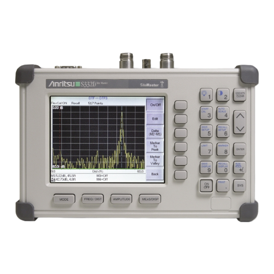
Site Master
S331D/S332D
Cable and Antenna Analyzer
Site Master is the preferred cable and antenna analyzer of
wireless providers, contractors and installers.
S331D
SiteMaster
Site Master
MS2712
SiteMaster
SpectrumMaster
Color display option shown
Programming Manual
MS2711D
MT8212A
Spectrum Master
SpectrumMaster
MS2712
Cell Master
CellMaster
™
CellMaster
MS2712
Advertisement
Table of Contents

Related Manuals for Anritsu Site Master S331D


Summary of Contents for Anritsu Site Master S331D
- Page 1 Site Master S331D/S332D Cable and Antenna Analyzer Site Master is the preferred cable and antenna analyzer of wireless providers, contractors and installers. Color display option shown S331D SiteMaster MS2711D Site Master MS2712 Spectrum Master SpectrumMaster MS2712 SiteMaster SpectrumMaster ™ Programming Manual MT8212A Cell Master CellMaster...
- Page 2 The Anritsu product(s) listed on the title page is (are) warranted against defects in materi- als and workmanship for one year from the date of shipment. Anritsu’s obligation covers repairing or replacing products which prove to be defective during the warranty period. Buyers shall prepay transportation charges for equipment re- turned to Anritsu for warranty repairs.
-
Page 3: Table Of Contents
Table of Contents Programming Overview ........1 Control Byte Summary. - Page 4 Upload Sweep Trace – Control Byte #36 (24h) ......62 Get Options – Control Byte #37 (25h) ........71 Query Power Level –...
- Page 5 Set Spectrum Analyzer Marker to Peak – Control Byte #109 (6Dh) ....86 Set Spectrum Analyzer Marker to Center – Control Byte #110 (6Eh) ....86 Set Spectrum Analyzer Attenuation –...
- Page 6 Set T1/E1 Receive Input Configuration Options - Control Word (A013h) (Option 50 only) ..101 Set T1/E1 Measurement Duration - Control Word (A014h) (Option 50 only) ....101 Set T1/E1 Data Logging - Control Word (A015h) (Option 50 only) .
-
Page 7: Programming Overview
The Site Master is a DTE-type serial device. Communication between the Site Master and a PC is accomplished over a null modem serial cable provided with the Site Master (Anritsu part number 800-441). Connect the cable to the Serial Interface connector on the Site Master test connector panel and to the appropriate COM port connector on the PC. -
Page 8: Documentation Conventions
Exiting Remote Mode To exit remote mode, send the Exit Remote Control byte #255 (FFh) to the Site Master. The Site Master sends a response byte of 255 (FFh) then exits remote mode. Remote mode can also be exited by pressing the ESCAPE/CLEAR front panel key. -
Page 9: Control Byte Summary
Control Byte Summary Control Byte Name 1 (01h) Setup System 2 (02h) Set VNA Frequency 3 (03h) Select Measurement Mode 4 (04h) Set VNA Scale 5 (05h) Set VNA Marker 6 (06h) Set VNA Single Limit 7 (07h) Set DTF Parameters 8 (08h) Set Time/Date 9 (09h) - Page 10 Control Byte Name 42 (2Ah) Power Meter Offset Mode 43 (2Bh) Power Meter Zero Mode Power Meter RMS 44 (2Ch) Averaging On/Off Power Meter Center 45 (2Dh) Frequency and Span 48 (30h) Trigger Sweep 50 (32h) Check Battery Status Set SPA Minimum Sweep 53 (35h) Time 54 (36h)
- Page 11 Control Byte Name Set Spectrum Analyzer 106 (6Ah) Resolution Bandwidth Freq Set Spectrum Analyzer 107 (6Bh) Video Bandwidth Freq Set Spectrum Analyzer 108 (6Ch) Sweep Mode Set Spectrum Analyzer 109 (6Dh) Marker to Peak Set Spectrum Analyzer 110 (6Eh) Marker to Center Set Spectrum Analyzer 111 (6Fh) Attenuation...
- Page 12 Control Byte Name Set T1/E1 Error Insert A004h Type/Value A005h Set T1/E1 Framing Mode Start and Stop T1/E1 A006h Measurement Insert Error for T1/E1 A007h Measurement A008h Get T1/E1 Pattern Get T1/E1 Frame Sync A009h Status Get T1/E1 Pattern Sync A00Ah Status A00Bh...
-
Page 13: Control Byte Descriptions
Control Byte Descriptions Setup System – Control Byte #1 (01h) Description: Sets system status flags and switches. The current value of the flags can be obtained by executing command #29, Query System Setup, and parsing the values from the appropriate bytes. The Site Master acts on the entire byte. So, the state of each of the bits must be defined every time the command is issued. -
Page 14: Select Measurement Mode - Control Byte #3 (03H)
Select Measurement Mode – Control Byte #3 (03h) Description: Sets the measurement mode of the Site Master. The response byte will not be sent until the mode change is complete. See control byte #29 (1Dh) response byte 3 for the current Site Master measurement mode. Bytes to Follow: 1 byte 1) Measurement Mode 00h: RL Frequency... -
Page 15: Set Site Master Vna Marker - Control Byte #5 (05H)
Set Site Master VNA Marker – Control Byte #5 (05h) Description: Sets an individual marker position and status in the current VNA measurement mode. See Control Byte #102 to set markers in Spectrum Analyzer mode. The Site Master sets the position of a marker by its relative position on the graph. The lowest position is 0 at the start frequency (or distance). -
Page 16: Set Dtf Parameter - Control Byte #7 (07H)
Notes: Return Loss & Cable Loss: Limit should be sent as ( dB * 1000 ) Maximum value sent is 60000 which represents 60.00 dB Minimum value sent is 0 which represents 0.0 dB SWR: Limit is in thousandths (of ratio), so it should be sent as ( ratio * 1000 ) Maximum value sent is 65530 which represents 65.53 Minimum value sent is 1000 which represents 1.00 Set DTF Parameter –... -
Page 17: Set Time/Date - Control Byte #8 (08H)
Set Time/Date – Control Byte #8 (08h) Description: Sets the current time and date. This Time/Date is stamped into all stored sweeps (for users’ reference). The Site Master stores bytes as ASCII text. Recommended time form is “hh:mm:ss” (hour:minute:sec). Recommended date format is “mm/dd/yyyy”... -
Page 18: Site Master Vna Single Sweep Mode On/Off - Control Byte #11 (0Bh)
Bytes to Follow: 1 byte 1) Serial Port Echo Status 00h = Off 01h = On Site Master Returns: 1 byte 255 (FFh) Operation Complete Byte 224 (E0h) Parameter Error : Invalid serial port echo status 238 (EEh) Time-out Error Site Master VNA Single Sweep Mode On/Off –... -
Page 19: Sequence Site Master Calibration - Control Byte #13 (0Dh)
Sequence Site Master Calibration – Control Byte #13 (0Dh) Description: Initiates a calibration step. The Site Master must be calibrated to give accurate measurements. The command sequence must be sent in correct order. i.e. Open -> Short -> Load. You can also abort the calibration by command –... -
Page 20: Store Sweep Trace - Control Byte #16 (10H)
Store Sweep Trace – Control Byte #16 (10h) Description: Saves current trace to the next available memory location. Trace name can be set using control byte #9, “Set Reference Number” before executing this command. Bytes to Follow: 0 bytes Site Master Returns: 5 bytes 1-4) Time/Date Stamp (In long integer format) Operation result: 255 (FFh) Operation Complete Byte... - Page 21 63) Stop Frequency 64) Stop Frequency (lowest byte) 65) Minimum Frequency Step Size (highest byte) 66) Minimum Frequency Step Size 67) Minimum Frequency Step Size 68) Minimum Frequency Step Size (lowest byte) 69) Scale Top (highest byte) 70) Scale Top 71) Scale Top 72) Scale Top (lowest byte) 73) Scale Bottom (highest byte)
- Page 22 164) Start Distance 165) Start Distance 166) Start Distance (lowest byte) 167) Stop Distance (highest byte) 168) Stop Distance 169) Stop Distance 170) Stop Distance (lowest byte) 171) Distance Marker 1 (highest byte) 172) Distance Marker 1 (lowest byte) 173) Distance Marker 2 (highest byte) 174) Distance Marker 2 (lowest byte) 175) Distance Marker 3 (highest byte) 176) Distance Marker 3 (lowest byte)
- Page 23 bit 7 : Unit of Measurement (1b = Metric, 0b = English) 194) Status Byte 4: (LSB) bit 0 - 1 : DTF Windowing Mode bit: 1 0 0 0 - Rectangular (No Windowing) 0 1 - Nominal Side Lobe 1 0 - Low Side Lobe 1 1 - Minimum Side Lobe bits 2 –...
- Page 24 77) Ref Level (highest byte) 78) Ref Level 79) Ref Level 80) Ref Level (lowest byte) 81) Scale per div (highest byte) 82) Scale per div 83) Scale per div 84) Scale per div (lowest byte) 85) Frequency Marker 1 (highest byte) 86) Frequency Marker 1 (lowest byte) 87) Frequency Marker 2 (highest byte)
- Page 25 266) VBW Setting (Frequency in Hz) 267) VBW Setting (Frequency in Hz) 268) VBW Setting (Frequency in Hz) (lowest byte) 269) OCC BW Method (0b if % of power, 1b = dB down) 270) OCC BW % Value (highest byte) 271) OCC BW % Value 272) OCC BW % Value 273) OCC BW % Value (lowest byte)
-
Page 26: Save System Setup - Control Byte #18 (12H)
300) Status Byte 5 ( 0b = Off/Beep if data is below line, 1b = On/Beep if data is above line) (LSB) bit 0 : Multiple Limit Upper Segment 3 Status On/Off bit 1 : Multiple Limit Upper Segment 3 Beep Level ABOVE/BELOW bit 2 : Multiple Limit Upper Segment 4 Status On/Off bit 3 : Multiple Limit Upper Segment 4 Beep Level ABOVE/BELOW bit 4 : Multiple Limit Upper Segment 5 Status On/Off... -
Page 27: Recall System Setup - Control Byte #19 (13H)
Bytes to Follow: 1 byte Location to save system setup parameters: 0 – 10 for SWR Mode, Return Loss Mode, Cable Loss Mode and DTF Mode 0 – 5 for Spectrum Analyzer Mode, Transmission Mode (Option 21) and Power Meter Mode (Option 29) 0 –... - Page 28 Site Master Mode Data Points (lower byte) Start Frequency (Frequency in Hz) (highest byte) Start Frequency Start Frequency Start Frequency (lowest byte) Stop Frequency (Frequency in Hz) (highest byte) Stop Frequency 10) Stop Frequency 11) Stop Frequency (lowest byte) 12) Scale Start (highest byte) 13) Scale Start 14) Scale Start 15) Scale Start (lowest byte)
- Page 29 106) Start Distance (highest byte) 107) Start Distance 108) Start Distance 109) Start Distance (lowest byte) 110) Stop Distance (highest byte) 111) Stop Distance 112) Stop Distance 113) Stop Distance (lowest byte) 114) Distance Marker 1 (higher byte) 115) Distance Marker 1 (lower byte) 116) Distance Marker 2 (higher byte) 117) Distance Marker 2 (lower byte) 118) Distance Marker 3 (higher byte)
- Page 30 152) Spectrum Analyzer Minimum Frequency Step Size (highest byte) 153) Spectrum Analyzer Minimum Frequency Step Size 154) Spectrum Analyzer Minimum Frequency Step Size 155) Spectrum Analyzer Minimum Frequency Step Size (lowest byte) 156) Ref Level (highest byte) 157) Ref Level 158) Ref Level 159) Ref Level (lowest byte) 160) Scale per div (highest byte)
- Page 31 340) RBW Setting (highest byte) 341) RBW Setting 342) RBW Setting 343) RBW Setting (lowest byte) 344) VBW Setting (highest byte) 345) VBW Setting 346) VBW Setting 347) VBW Setting (lowest byte) 348) OCC BW Method 349) OCC BW % Value (highest byte) 350) OCC BW % Value 351) OCC BW % Value 352) OCC BW % Value (lowest byte)
- Page 32 bits 6 - 7 : Not Used 249) Status Byte 4: (0b = Off, 1b = On) (LSB) bit 0 : Not Used bit 1 : Spectrum Analyzer Mode Marker 2 Delta On/Off bit 2 : Spectrum Analyzer Mode Marker 3 Delta On/Off bit 3 : Spectrum Analyzer Mode Marker 4 Delta On/Off bits 4-7: Not Used 250) Status Byte 5: ( 0b = Off , 1b = On)
- Page 33 bit 5 : SPA Multiple Limit Upper Segment 1 Beep Level ABOVE/BELOW bit 6 : SPA Multiple Limit Upper Segment 2 Status On/Off bit 7 : SPA Multiple Limit Upper Segment 2 Beep Level ABOVE/BELOW 256) Status Byte 11 : (0b = Off/Beep if data is BELOW line , 1b = On/Beep if data is ABOVE line) (LSB) bit 0 : SPA Multiple Limit Upper Segment 3 Status On/Off bit 1 : SPA Multiple Limit Upper Segment 3 Beep Level ABOVE/BELOW...
-
Page 34: Trigger Self-Test - Control Byte #21 (15H)
bit 5: Channel Power On/Off bit 6: Adjacent Channel Power On/Off bit 7: Not Used 398) Printer Type 399) Current Language (0 = English, 1 = French, 2 = German, 3 = Spanish, 4 = Chinese, 5 = Japanese) 400) LCD Contrast Value (0-255) 401) RTC battery (higher byte) 402) RTC battery (lower byte) -
Page 35: Read Fail Counter - Control Byte #22 (16H)
Notes: Battery Voltage in 1/10th of a Volt (e.g. 124 = 12.4 Volts) Temperature in 1/10th of degree Celsius (e.g., 362 = 36.2°C) or degree Fahrenheit (e.g., 934 = 93.4°F), depending on the current measurement unit (Metric or English) selected Read Fail Counter –... -
Page 36: Upload Spa Sweep Trace - Control Byte #26 (1Ah)
Upload SPA Sweep Trace – Control Byte #26 (1Ah) NOTE: This command exists for backward compatibility with the S33xC models. Features new to the S33xD models are not available here. To access the new features, use Control Byte #33 (21h). This command cannot be used with a frequency converter module attached (Option 6 required). - Page 37 71) Marker 2 (lower byte) 72) Marker 3 (higher byte) 73) Marker 3 (lower byte) 74) Marker 4 (higher byte) 75) Marker 4 (lower byte) 76) Marker 5 (higher byte) 77) Marker 5 (lower byte) 78) Marker 6 (higher byte) 79) Marker 6 (lower byte) 80) Single Limit (highest byte)
- Page 38 262) Attenuation 263) Attenuation 264) Attenuation (lowest byte) 265-280) Antenna Name (16 bytes in ASCII) 281) Status Byte 1: (0b = Off, 1b = On) (LSB) bit 0 : Marker 1 On/Off bit 1 : Marker 2 On/Off bit 2 : Marker 3 On/Off bit 3 : Marker 4 On/Off bit 4 : Marker 5 On/Off bit 5 : Marker 6 On/Off...
-
Page 39: Query Sweep Memory - Control Byte #27 (1Bh)
288) Reference Level Offset (highest byte) 289) Reference Level Offset 290) Reference Level Offset 291) Reference Level Offset (lowest byte) 292-321) Not Used 322-1921) Sweep Data (400 points * 4 bytes/point = 1600 bytes) 4 bytes for each data point 1. - Page 40 48) Stop Frequency (highest byte) 49) Stop Frequency 50) Stop Frequency 51) Stop Frequency (lowest byte) 52) Minimum Frequency Step Size (highest byte) 53) Minimum Frequency Step Size 54) Minimum Frequency Step Size 55) Minimum Frequency Step Size (lowest byte) 56) Scale Top (highest byte) 57) Scale Top 58) Scale Top...
- Page 41 150) Start Distance (highest byte) 151) Start Distance 152) Start Distance 153) Start Distance (lowest byte) 154) Stop Distance (highest byte) 155) Stop Distance 156) Stop Distance 157) Stop Distance (lowest byte) 158) Distance Marker 1 (higher byte) 159) Distance Marker 1 (lower byte) 160) Distance Marker 2 (higher byte) 161) Distance Marker 2 (lower byte) 162) Distance Marker 3 (higher byte)
-
Page 42: Query System Status - Control Byte #29 (1Dh)
bit 5 : Cal On/Off bit 6 : Limit Type ( 0b = Single; 1b = Multiple) bit 7 : Unit of measurement (1b = Metric, 0b = English) 181) Status Byte 4: (LSB) bit 0 - 1 : DTF Windowing Mode bit: 1 0 0 0 - Rectangular (No Windowing) 0 1 - Nominal Side Lobe... - Page 43 Number of Following Bytes (higher byte) Number of Following Bytes (lower byte) Measurement Mode Printer Type Current Language (00h = English, 01h = French, 02h = German, 03h = Spanish, 04h = Chinese, 05h = Japanese) LCD Contrast Value (0-255) Date Format (00h = MM/DD/YYYY, 01h = DD/MM/YYYY, 02h = YYYY/MM/DD) RTC battery...
- Page 44 56) Site Master VNA Single Limit (highest byte) 57) Site Master VNA Single Limit 58) Site Master VNA Single Limit 59) Site Master VNA Single Limit (lowest byte) 60) VNA Multiple Limit Segment # (1) 61) VNA Multiple Limit Segment Status (0h = Off, 01h = On ) 62) VNA Multiple Limit Segment Start X (highest byte) 63) VNA Multiple Limit Segment Start X 64) VNA Multiple Limit Segment Start X...
- Page 45 156) Cable Loss 157) Cable Loss (lowest byte) 158) Average Cable Loss (highest byte) 159) Average Cable Loss 160) Average Cable Loss 161) Average Cable Loss (lowest byte) 162) Status Byte 1: ( 0b = Off , 1b = On) (LSB) bit 0 : Site Master Marker 1 On/Off bit 1 : Site Master Marker 2 On/Off...
- Page 46 bit 7 : Not Used 168) Status Byte 7: (0b = Off, 1b = On) (LSB) bits 0-1: Not Used bit 2: DIST-RL Multiple Limit Segment 1 Status On/Off bit 3: DIST-RL Multiple Limit Segment 2 Status On/Off bit 4: DIST-RL Multiple Limit Segment 3 Status On/Off bit 5: DIST-RL Multiple Limit Segment 4 Status On/Off bit 6: DIST-RL Multiple Limit Segment 5 Status On/Off bit 7: Not Used...
- Page 47 45) Spectrum Analyzer Minimum Frequency Step Size 46) Spectrum Analyzer Minimum Frequency Step Size 47) Spectrum Analyzer Minimum Frequency Step Size (lowest byte) 48) Ref Level (highest byte) 49) Ref Level 50) Ref Level 51) Ref Level (lowest byte) 52) Scale per div (highest byte) 53) Scale per div 54) Scale per div 55) Scale per div (lowest byte)
- Page 48 87) SPA Multiple Upper Limit 1 End Y (Power Level) (lowest byte) 88-231) SPA Multiple Upper Limits 2-5, SA Multiple Lower Limits 1-5 (see bytes 72-87 for format) 232) RBW Setting (highest byte) 233) RBW Setting 234) RBW Setting 235) RBW Setting (lowest byte) 236) VBW Setting (highest byte) 237) VBW Setting 238) VBW Setting...
- Page 49 bit 4 : SPA Multiple Limit Upper Segment 1 Status On/Off bit 5 : SPA Multiple Limit Upper Segment 1 Beep Level ABOVE/BELOW bit 6 : SPA Multiple Limit Upper Segment 2 Status On/Off bit 7 : SPA Multiple Limit Upper Segment 2 Beep Level ABOVE/BELOW 273) Status Byte 4 : (0b = Off/Beep if data is BELOW line, 1b = On/Beep if data is ABOVE line) (LSB) bit 0 : SPA Multiple Limit Upper Segment 3 Status On/Off...
- Page 50 0-1: Trace Math Operation (00b = A only, 01b = A-B, 10b = A+B) bit 2: Max Hold On/Off bit 3: Min Hold On/Off bits 4-7: Not Used 303) Impedance (00h = 50W, 0Ah = 75W Anritsu Adapter, 0Ch = 75W Other Adapter) 304) Impedance Loss (higher byte) 305) Impedance Loss (lower byte)
- Page 51 321) Frequency Scale Factor (higher byte) 322) Frequency Scale Factor (lower byte) 323) Frequency Range Minimum 324) Frequency Range Minimum 325) Frequency Range Minimum 326) Frequency Range Minimum (lowest byte) 327) Frequency Range Maximum 328) Frequency Range Maximum 329) Frequency Range Maximum 330) Frequency Range Maximum (lowest byte) 331) Marker Type 332-400) Not Used...
- Page 52 51) Power Meter Relative 52) Power Meter Relative 53) Power Meter Relative (lowest byte) 54) Power Meter Status (00h = Off, 01h = On) 55) Power Meter Unit (00h = Watts, 01h = dBm) 56) Power Meter Relative Status (00h = Off, 01h = On) 57) Power Meter Offset Status (00h = Off, 01h = On) 58) Power Meter RMS Averaging Level (00h = Off, 01h = Low, 02h = Medium, 03h = High) 59) Frequency Scale Factor...
- Page 53 137) T1 1 User Defined Loop Up (lower byte) 138) T1 2 User Defined Loop Up (higher byte) 139) T1 2 User Defined Loop Up (lower byte) 140) T1 1 User Defined Loop Down (higher byte) 141) T1 1 User Defined Loop Down (lower byte) 142) T1 2 User Defined Loop Down (higher byte) 143) T1 2...
-
Page 54: Select Printer Type - Control Byte #30 (1Eh)
141) E1 1 User Defined Loop Down (lowest byte) 142) E1 2 User Defined Loop Down (highest byte) 143) E1 2 User Defined Loop Down (lowest byte) 144) E1 User Defined Pattern (highest byte) 145) E1 User Defined Pattern 146) E1 User Defined Pattern 147) E1 User Defined Pattern (lowest byte) 148) E1 Bit Error Insert Value (1-1000) (higher byte) 149) E1 Bit Error Insert Value (lower byte) -
Page 55: Select Dtf Windowing - Control Byte #31 (1Fh)
Select DTF Windowing – Control Byte #31 (1Fh) Description: Select DTF Windowing Methods. DTF windowing allows you to make a trade off between side lobe height and resolution. Bytes to Follow: 1 byte Windowing Method 00h = Rectangular (finest resolution, highest side lobes) 01h = Nominal Side Lobe (balance between resolution and side lobes) 02h = Low Side Lobe 03h = Minimum Side Lobe... - Page 56 Current Instrument Date Format Not Used 5-11) Model Number (7 bytes in ASCII) 12-15) Software Version (4 bytes ASCII) 16) Measurement Mode 17-20) Time/Date (in Long Integer 21-30) Date in String Format (mm/dd/yyyy) 31-38) Time in String Format (hh:mm:ss) 39-54) Reference number stamp (16 bytes in ASCII) 55-56) # data points (130, 259 or 517 or 401 or 100)
- Page 57 89) Single Limit (highest byte) 90) Single Limit 91) Single Limit 92) Single Limit (lowest byte) 93) Multiple Limit Segment # (1) 94) Multiple Limit Segment Status 95) Multiple Limit Start X (highest byte) 96) Multiple Limit Start X 97) Multiple Limit Start X 98) Multiple Limit Start X (lowest byte) 99) Multiple Limit Start Y (higher byte) 100) Multiple Limit Start Y (lower byte)
- Page 58 189) Cable Loss 190) Cable Loss (lowest byte) 191) Average Cable Loss (highest byte) 192) Average Cable Loss 193) Average Cable Loss 194) Average Cable Loss (lowest byte) 195) Status Byte 1: ( 0b = Off , 1b = On) (LSB) bit 0 : Marker 1 On/Off bit 1 : Marker 2 On/Off...
- Page 59 2. gamma 3. gamma 4. gamma (lowest byte) 5. phase (highest byte) 6. phase 7. phase 8. phase (lowest byte) Notes: return loss = –20* (log(gamma) / log(10)) VSWR = (1+gamma)/(1-gamma) phase compares the reflected to the incident (reference) For Spectrum Analyzer and Transmission Measurement (Option 21) Modes: 57) Start Frequency (highest byte) 58) Start Frequency...
- Page 60 90) Frequency Marker 3 (lower byte) 91) Frequency Marker 4 (higher byte) 92) Frequency Marker 4 (lower byte) 93) Frequency Marker 5 (higher byte) 94) Frequency Marker 5 (lower byte) 95) Frequency Marker 6 (higher byte) 96) Frequency Marker 6 (lower byte) 97) Single Limit (highest byte) 98) Single Limit...
- Page 61 292) Status Byte 1: ( 0b = Off , 1b = On) (LSB) bit 0 : Marker 1 On/Off bit 1 : Marker 2 On/Off bit 2 : Marker 3 On/Off bit 3 : Marker 4 On/Off bit 4 : Marker 5 On/Off bit 5 : Marker 6 On/Off bits 6-7: Not Used 293) Status Byte 2: ( 0b = Off , 1b = On)
- Page 62 5: Bias Tee On/Off (Option 10 only) bit 6: Occupied BW Measurement On/Off bit7: Not Used 332) Impedance (00h = 50W, 0Ah = 75W Anritsu Adapter, 0Ch = 75W Other Adapter) 333) Impedance Loss (higher byte) 334) Impedance Loss (lower byte) 173 Value sent as ( value in dBm * 1000 ) + 270,000 174 1 byte in MHz (i.e.
- Page 63 335) Frequency Scale Factor (higher byte) 336) Frequency Scale Factor (lower byte) 337) Frequency Range Minimum 338) Frequency Range Minimum 339) Frequency Range Minimum 340) Frequency Range Minimum (lowest byte) 341) Frequency Range Maximum 342) Frequency Range Maximum 343) Frequency Range Maximum 344) Frequency Range Maximum (lowest byte) 345) Linked Trace Number (1-200) 346) Status Byte 9 (0b=Off, 1b=On)
- Page 64 1. dBm (highest byte) 2. dBm 3. dBm 4. dBm (lowest byte) For Power Meter Mode (Option 29): 57) Power Meter Mode (00h = Off, 01h = On) 58) Power Meter Unit (00h = dBm, 01h = Watts) 59) Start Frequency (highest byte) 60) Start Frequency 61) Start Frequency...
- Page 65 95) Channel Selection (lower byte) 96) Frequency Scale Factor (higher byte) 97) Frequency Scale Factor (lower byte) 98) Frequency Range Minimum 99) Frequency Range Minimum 100) Frequency Range Minimum 101) Frequency Range Minimum (lowest byte) 102) Frequency Range Maximum 103) Frequency Range Maximum 104) Frequency Range Maximum 105) Frequency Range Maximum (lowest byte) 106 –...
- Page 66 79) Pattern Sync Status (00h: In Sync, 01h: Out-of-Sync) 80) Carrier Status (00h: In Sync, 01h: Out-of-Sync) 81) Rx Alarms (bit 0: Receiving AIS, bit 1: Receiving RAI, bit 2: Receiving E1 MMF error) 82) BPV Error Count (highest byte) 83) BPV Error Count 84) BPV Error Count 85) BPV Error Count (lowest byte)
-
Page 67: Set Site Master Vna Trace Overlay - Control Byte #34 (22H)
656) Vpp or dBdsx (higher byte) 657) Vpp or dBdsx (lower byte) 658) T1 or E1 Receive Frequency (in Hz) 659) T1 or E1 Receive Frequency (in Hz) 660) T1 or E1 Receive Frequency (in Hz) 661) T1 or E1 Receive Frequency (in Hz) (lowest byte) 662 –... -
Page 68: Upload Sweep Trace - Control Byte #36 (24H)
255 (FFh) Operation Complete Byte 224 (E0h) Parameter Error: Not enough bytes transferred, “B” trace requested to be used in calculations or displayed, but no trace or invalid trace specified 238 (EEh) Time-out Error Upload Sweep Trace – Control Byte #36 (24h) This command is new to the S33xD. - Page 69 67) Frequency Marker 2 (lower byte) 68) Frequency Marker 3 (higher byte) 69) Frequency Marker 3 (lower byte) 70) Frequency Marker 4 (higher byte) 71) Frequency Marker 4 (lower byte) 72) Frequency Marker 5 (higher byte) 73) Frequency Marker 5 (lower byte) 74) Frequency Marker 6 (higher byte) 75) Frequency Marker 6 (lower byte) 76) Single Limit Line Value (highest byte)
- Page 70 170) Relative Propagation Velocity (highest byte) 171) Relative Propagation Velocity 172) Relative Propagation Velocity 173) Relative Propagation Velocity (lowest byte) 174) Cable Loss (highest byte) 175) Cable Loss 176) Cable Loss 177) Cable Loss (lowest byte) 178) Average Cable Loss (highest byte) 179) Average Cable Loss 180) Average Cable Loss...
- Page 71 188) VNA Signal Standard (lower byte) 189-314) Not Used 315-1354) Sweep Data (130 points * 8 bytes/point= 1040 bytes) 315-2386) (259 points * 8 bytes/point= 2072 bytes) 315-4450) (517 points * 8 bytes/point= 4136 bytes) 8 bytes for each data point 1.
- Page 72 66) Scale per div 67) Scale per div (lowest byte) 68) Marker 1 (higher byte) 69) Marker 1 (lower byte) 70) Marker 2 (higher byte) 71) Marker 2 (lower byte) 72) Marker 3 (higher byte) 73) Marker 3 (lower byte) 74) Marker 4 (higher byte) 75) Marker 4 (lower byte) 76) Marker 5 (higher byte)
- Page 73 254) OCC BW dBc (0-120) 255) Attenuation (highest byte) 256) Attenuation 257) Attenuation 258) Attenuation (lowest byte) 259-274) Antenna Name (16 bytes in ASCII) 275) Status Byte 1: (0b = Off, 1b = On) (LSB) bit 0 : Marker 1 On/Off bit 1 : Marker 2 On/Off bit 2 : Marker 3 On/Off bit 3 : Marker 4 On/Off...
- Page 74 6: Occupied BW Measurement On/Off bit 7: Not Used 315) Impedance (00h = 50W, 0Ah = 75W Anritsu Adapter, 0Ch = 75W Other Adapter) 239 Value sent as (Value in dBm * 1000 ) + 270,000 240 byte in MHz (i.e. 20 = 20MHz) 241 Index into Standard List (use control byte #89 to retrieve the ASCII string name).
- Page 75 316) Impedance Loss (higher byte) 317) Impedance Loss (lower byte) 318) Frequency Scale Factor (higher byte) 319) Frequency Scale Factor (lower byte) 320) Frequency Range Minimum 321) Frequency Range Minimum 322) Frequency Range Minimum 323) Frequency Range Minimum (lowest byte) 324) Frequency Range Maximum 325) Frequency Range Maximum 326) Frequency Range Maximum...
- Page 76 3. dBm 4. dBm (lowest byte) For T1/E1 Modes (Option 50): 44) Receive Input (00h: Terminate, 01h: Bridged, 02h: Monitor) 45) Framing Mode 46) Line Coding (01h: B8ZS, 02h: AMI, 03h: HDB3) 47) Tx Level (Valid for T1 Only) (01h: 0 dB, 02h: -7.5 dB, 03h: -15 dB) 48) Clock Source (00h: External, 01h: Internal) 49) Error Insert Type (00h: Frame Error, 01h: BPV, 02h: Bit Errors, 04h: RAI, 05h: AIS) 50) Loop Code (Valid for T1 Only) (00h: CSU, 01h: NIU, 02h: User 1, 03h: User 2)
-
Page 77: Get Options - Control Byte #37 (25H)
86) E Bit Error Count (E1 Only) 87) E Bit Error Count (E1 Only) 88) E Bit Error Count (E1 Only) (lowest byte) 89) Errored Seconds (highest byte) 90) Errored Seconds 91) Errored Seconds 92) Errored Seconds (lowest byte) 93) Bit Count (highest byte) 94) Bit Count 95) Bit Count 96) Bit Count (lowest byte) -
Page 78: Query Power Level - Control Byte #39 (27H) (Option 29 Only)
Option 6: “6/” Option 10: “10/” Option 21: “21/” Option 29: “29/” Option 50: “50/” If no options are installed: “None” Query Power Level – Control Byte #39 (27h) Description: Return Power Level at the RF In port. Also returns power meter settings. Bytes to Follow: 0 bytes Site Master Returns: 30 bytes 1) Status Byte # 1(0b = Off, 1b = On) -
Page 79: Power Meter Relative Mode On/Off - Control Byte #41 (29H) (Option 29 Only)
Power Meter Relative Mode On/Off – Control Byte #41 (29h) Description: Enable or disable Power Meter Relative Mode. Bytes to Follow: 1 byte Relative Mode State 00h = Off 01h = On w/ trigger (use the current power level as a reference power level) Site Master Returns: 1 byte 255 (FFh) Operation Complete Byte 224 (E0h) Parameter Error: Invalid parameter... -
Page 80: Power Meter Center Freq And Span Setup - Control Byte #45 (2Dh) (Option 29 Only)
255 (FFh) Operation Complete Byte 224 (E0h) Parameter Error: Invalid state 238 (EEh) Time-out Error Power Meter Center Freq and Span Setup – Control Byte #45 (2Dh) Description: Sets the center frequency and span frequency for the Power Meter mode. If Option 6 is installed and the frequency converter module is attached, the center frequency should be scaled by the scale factor of the module. -
Page 81: Set Spa Minimum Sweep Time - Control Byte #53 (35H)
Site Master Returns: 17 bytes 1-2) Battery Status flags ( Refer to Smart Battery Data Spec 5.1.2.1) 3-4) State of Charge (unsigned integer 0 to 100(%)Full) 5-6) Battery Voltage (unsigned integer 0 to 65535 in mV) 7-8) Battery Current (signed integer -32,768 to +32,7687 mA, positive = Charging) 9-10) Battery Average current (signed integer -32,768 to +32,7687 mA, positive = Charging) 11-12) -
Page 82: Automatically Save Runtime Setup - Control Byte #64 (40H)
Bytes to Follow: 0 bytes Site Master Returns: 13 bytes 1-2) Model # (unsigned integer, 14h for Site Master S331D, 15h for Site Master S332D) 3-9) Extended Model # (7 bytes in ASCII) 10-13) Software Version - 4 bytes (ASCII) Enter Remote Mode Immediately –... -
Page 83: Write Custom Cable - Control Byte #80 (50H)
1-2) Model # (unsigned integer, 14h for Site Master S331D, 15h for Site Master S332D) 3-9) Extended Model # (7 bytes in ASCII) 10-13) Software Version (4 bytes in ASCII) Write Custom Cable – Control Byte #80 (50h) Description: Write a cable parameter in the custom cable list. -
Page 84: Write Antenna - Control Byte #82 (52H)
Write Antenna – Control Byte #82 (52h) Description: Receives an antenna to the Site Master via the serial port. An antenna is described with an index into the list (1-10) and an ASCII name that appears in the list on the Site Master. Each antenna can have up to 60 antenna factors. -
Page 85: Set Field Strength Measurement - Control Byte #84 (54H)
12. Anritsu # 2000-1031 (MAXRAD MPA1850 - 1850-1990 MHz) 13. Anritsu # 2000-1032 (MAXRAD MPA2450 - 2400-2483.5 MHz) 14. Anritsu # 2000-1200 (Centurion EXC SM806 - 806-899 MHz) 15. Anritsu # 2000-1035 (Centurion EXE-902-SM - 896-941 MHz) If the FCN4760 frequency converter module is attached, the standard antenna is: 11. -
Page 86: Read Channel Power - Control Byte #86 (56H)
Read Channel Power – Control Byte #86 (56h) Description: Read the current channel power or the channel power of a stored trace. Send a 0 (zero) following the command to read the current channel power measurement (i.e. the one that is updated as the unit is sweeping). -
Page 87: Read Signal Standard Name - Control Byte #89 (59H)
Send a 0 (zero) following the command to read the current adjacent channel power measurement (i.e. the one that is updated as the unit is sweeping). Send 1-200 to read the channel power associated with a stored trace (use Query Trace Names, #24, to obtain trace numbers). If Option 6 is installed and the frequency converter module is attached, the frequencies should be scaled by the scale factor of the module. -
Page 88: Measure Occ Bw Db Down - Control Byte #97 (61H)
9-12) Low Frequency OCC BW 13-16) High Frequency OCC BW Measure OCC BW dB Down – Control Byte #97 (61h) Description: Measure OCC BW with dB down method. If Option 6 is installed and the frequency converter module is attached, the frequencies should be scaled by the scale factor of the module. -
Page 89: Set Spectrum Analyzer Start/Stop Frequency - Control Byte #99 (63H)
Set Spectrum Analyzer Start/Stop Frequency – Control Byte #99 (63h) Description: Sets the spectrum analyzer start and stop frequencies. If Option 6 is installed and the frequency converter module is attached, the frequencies should be scaled by the scale factor of the module. -
Page 90: Set Spectrum Analyzer Marker - Control Byte #102 (66H)
Ref Level Ref Level (lowest byte) dB/div (highest byte) dB/div dB/div dB/div (lowest byte) Site Master Returns: 1 byte 255 (FFh) Operation Complete Byte 224 (E0h) Parameter Error: Invalid scale 238 (EEh) Time Out Error Notes: Ref Level is sent as the (Ref Level * 1000) + 270,000 (0 dBm = 270,000, 20 dBm = 290000, -120 dBm = 150,000) Scale should be sent as (dBm * 1000) (e.g., -12.34 dBm = -12340) Set Spectrum Analyzer Marker –... -
Page 91: Set Spectrum Analyzer Peak Hold - Control Byte #105 (69H)
Set Spectrum Analyzer Peak Hold – Control Byte #105 (69h) Description: Sets the max hold and min hold settings on the Spectrum Analyzer. Bytes to Follow: 1 byte Peak Hold State 00h – Peak Hold Off 01h – Max Hold On 02h –... -
Page 92: Set Spectrum Analyzer Sweep Mode - Control Byte #108 (6Ch)
255 (FFh) Operation Complete Byte 224 (E0h) Parameter Error: Invalid VBW Index 238 (EEh) Time Out Error Set Spectrum Analyzer Sweep Mode – Control Byte #108 (6Ch) Description: Enables or disables the Single Sweep Mode during Spectrum Analyzer mode of operation. Single Sweep Mode activates once the Site Master exits from the remote mode. -
Page 93: Set Spectrum Analyzer Attenuation - Control Byte #111 (6Fh)
Set Spectrum Analyzer Attenuation – Control Byte #111 (6Fh) NOTE: This command exists for backward compatibility with the S33xC models. Features new to the S33xD models are not available here. To access the new features use Control Byte #143 (8Fh). Description: Sets the attenuation for the Site Master Spectrum Analyzer mode. -
Page 94: Set Spectrum Analyzer Multiple Limit - Control Byte #113 (71H)
Site Master Returns: 1 byte 255 (FFh) Operation Complete Byte 224 (E0h) Parameter Error: Invalid limit segment, status or value 238 (EEh) Time Out Error Notes: Limit Value depends on the current display mode selected. Return Loss &: Limit should be sent as ( dB * 1000 ) Cable Loss Maximum value sent is 60000 which represents 60.00 dB Minimum value sent is 0 which represents 0.0 dB... -
Page 95: Set Return Spectrum Analyzer Sweep Time - Control Byte #114 (72H)
16) Limit Value End X (lowest byte) 17) Limit Value End Y (highest byte) 18) Limit Value End Y 19) Limit Value End Y 20) Limit Value End Y (lowest byte) Site Master Returns: 1 byte 255 (FFh) Operation Complete Byte 224 (E0h) Parameter Error: Invalid limit segment, status or value 238 (EEh) Time Out Error Set Return Spectrum Analyzer Sweep Time –... -
Page 96: Read Marker Value - Control Byte #117 (75H)
Read Marker Value – Control Byte #117 (75h) Description: Returns the frequency location of the specified marker, and the value at that location. If Option 6 is installed and the frequency converter module is attached, the frequency will be scaled by the scale factor of the module. -
Page 97: Read Instacal Module Ascii Serial Number - Control Byte #124 (7Ch)
Read InstaCal Module ASCII Serial Number – Control Byte #124 (7Ch) Description: Returns the InstaCal Module serial number in ASCII. Bytes to Follow: 1 byte Serial number storage location (01h=main serial, 02h=secondary) Site Master Returns: 8 bytes 1-8) Serial Number, in ASCII Set Site Master Marker (Peak/Valley) –... -
Page 98: Check Spectrum Analyzer External Reference - Control Byte #134 (86H)
Check Spectrum Analyzer External Reference – Control Byte #134 (86h) Description: Checks to see if Spectrum Analyzer external reference is present. If it is, it then checks to see if it is at the correct frequency for PLL locking. Bytes to Follow: 0 bytes Site Master Returns: 1 byte On Success: 00h –... -
Page 99: Set Spectrum Analyzer Resolution Bandwidth - Control Byte #141 (8Dh)
255 (FFh) Operation Complete Byte 224 (E0h) Parameter Error 238 (EEh) Time-out Error Set Spectrum Analyzer Resolution Bandwidth – Control Byte #141 (8Dh) NOTE: This command is new to the Site Master S33xD models. Use it instead of Control Byte #106 to access the RBW. -
Page 100: Set Am/Fm Demodulation - Control Byte #145 (91H)
Automatic control couples the attenuation to the reference level. Note that setting the attenuation using this command automatically sets the attenuation coupling to “MANUAL”, thereby allowing it to be defined independently of the reference level. Bytes to Follow: 1 byte Attenuation (0 –... -
Page 101: Set Baud Rate - Control Byte #197 (C5H)
Set Baud Rate – Control Byte #197 (C5h) Description: Set baud rate for this session. An invalid setting returns the baud rate to 9600. Bytes to Follow: 1 byte Baud Rate Index 00h = 9600 baud 01h = 19200 baud 02h = 38400 baud 03h = 56000 baud 04h = 115200 baud... -
Page 102: Read Ascii Serial Number - Control Byte #225 (E1H)
Read ASCII Serial Number – Control Byte #225 (E1h) Description: Reads and returns the Site Master serial number as 8 ASCII bytes. Bytes to Follow: 1 byte Serial number storage location 01h = Main (External) Serial Number, 02h = Secondary (Motherboard) Serial Number 03h = T1/E1 Serial Number Site Master Returns: 8 bytes 1-8) Serial Number (in ASCII) -
Page 103: Set T1/E1 Pattern - Control Word (A003H) (Option 50 Only)
Clock Source 00h: Internal 01h: External Site Master Returns: 1 byte 255 (FFh) Operation Complete Byte 224 (E0h) Parameter Error: Invalid clock source 238 (EEh) Time Out Error Set T1/E1 Pattern – Control Word (A003h) Description: Sets the data pattern of T1/E1 measurement mode. Bytes to Follow: 2 bytes Data Pattern 00h: AUTO_DETECT... -
Page 104: Set T1/E1 Framing Mode - Control Word (A005H) (Option 50 Only)
255 (FFh) Operation Complete Byte 224 (E0h) Parameter Error: Invalid error type or value 238 (EEh) Time Out Error Set T1/E1 Framing Mode – Control Word (A005h) Description: Sets the Framing Mode of T1/E1 measurement. Bytes to Follow: 1 byte Framing Mode 00h: Auto T1 Tester Only... -
Page 105: Get T1/E1 Frame Sync Status - Control Word (A009H) (Option 50 Only)
238 (EEh) Time Out Error Get T1/E1 Frame Sync Status – Control Word (A009h) Description: Get the frame sync status of T1 /E1. Bytes to Follow: 0 bytes Site Master Returns: 1 byte Frame Sync Status (00h: Framed; 01h: Unframed) 238 (EEh) Time Out Error Get T1/E1 Pattern Sync Status –... -
Page 106: Set T1/E1 Line Coding Options - Control Word (A00Dh) (Option 50 Only)
12) CRC (lower byte) 13) Errored Seconds (highest byte) 14) Errored Seconds 15) Errored Seconds 16) Errored Seconds (lowest byte) 13) E Bits (higher byte) 14) E Bits (lower byte) 15) Errored Seconds (highest byte) 16) Errored Seconds 17) Errored Seconds 18) Errored Seconds (lowest byte) 238 (EEh) Time Out Error Set T1/E1 Line Coding Options –... -
Page 107: Set T1/E1 Receive Input Configuration Options - Control Word (A013H) (Option 50 Only)
Bytes to Follow: 0 bytes Site Master Returns: 3 bytes Volts peak-to-peak (higher byte) Volts peak-to-peak (lower byte) 255 (FFh) Operation Complete Byte 238 (EEh) Time-out Error Set T1/E1 Receive Input Configuration Options - Control Word (A013h) (Option 50 only) Description: Sets the Rx Input Configuration for the T1/E1 modes. -
Page 108: Read T1/E1 Dbdsx - Control Word (A016H) (Option 50 Only)
00h: Off 01h: On Site Master Returns: 1 byte 255 (FFh) Operation Complete Byte 224 (E0h) Parameter Error: Invalid status or not enough memory 238 (EEh) Time Out Error Read T1/E1 dBdsx - Control Word (A016h) Description: Initiates a voltage measurement on the T1 board and returns the result in dBdsx. The resolution is 0.1 dB and is offset by 350 so that only positive values are returned. -
Page 109: Select Spa/Power Meter Signal Standard - Control Word (A103H)
Site Master Returns: 1 byte Status Byte 255 (FFh) Operation Complete Byte Select SPA/Power Meter Signal Standard - Control Word (A103h) Description: Selects a Signal Standard. Use this command for both Spectrum Analyzer and Power Meter modes. See the “Signal Standards” section for a list of standards and their indices. Bytes to Follow: 1 byte Signal Standard - See the “Signal Standards”... -
Page 110: Read External Module Serial Number - Control Word (A202H) (Option 6 Only)
Read External Module Serial Number – Control Word (A202h) Description: Sets the serial number of the attached external converter module (Option 6). For example, serial number 12345678 will be received as: 8,1,2,3,4,5,6,7,8,ff Bytes to Follow: 0 bytes Site Master Returns: 10 bytes Length of Serial Number (8) 2-9) Serial Number 10) 255 (FFh) Operation Complete Byte... -
Page 111: Clear Module Fail Counter - Control Word (A205H) (Option 6 Only)
Fail Counter (higher byte) Fail Counter (lower byte) 255 (FFh) Operation Complete Byte 255 (FFh) Operation Complete Byte 224 (E0h) Parameter Error: Module not attached 238 (EEh) Time Out Error Clear Module Fail Counter – Control Word (A205h) Description: Sets the module lock fail counter to 0. Bytes to Follow: 0 bytes Site Master Returns: 1 byte 255 (FFh) Operation Complete Byte... - Page 112 24) VNA Integration Test - Reserved 25) SPA LO Test - Status (01h: Pass, 00h: Fail, FFh: SPA board not installed) 26) SPA LO Test - Failed data point # 27) SPA LO Test - Failed LO # 28) End of Data (FFh) S331D + Option 29 or S332D (w/o Option 6): 28 bytes Temperature in 1/10th of degree Celsius (e.g., 362 = 36.2°...
- Page 113 18) H/W Config - T1E1 COLD ID 19) VNA PLL Lock Failure Test - Status (01h: Pass, 00h: Fail) 20) VNA PLL Lock Failure Test - Failed data point # (Ignore this byte if the Lock Fail Test Status was Pass) 21) VNA PLL Lock Failure Test - Failed PLL # (Ignore this byte if the Lock Fail Test Status was Pass) 22) VNA Integration Test - Status (01h: Pass, 00h: Fail) 23) VNA Integration Test - Failed data point # (Ignore this byte if the Integration Test Status was Pass)
-
Page 114: Programming Examples
This section contains several sample functions written in C, (and one in Visual Basic) that can be used as references when programming Anritsu Handheld Products. These include functions to set up the comm port, enter and exit remote mode, and set the reference level of the spectrum analyzer. - Page 115 /*********************************************************************/ unsigned char SetSPAScale(unsigned long ReferenceLevel, unsigned long dBScale, BYTE *ResponseBytes) Description: This function implements control byte #101, Set Spectrum Analyzer Scale. analyzer reference level and scale (dB/div). Inputs : RefLevel = reference level value dBScale = scale value NOTE: This function assumes the values have already been checked to fall in the valid range and scaled according to the formulas in the...
- Page 116 WriteToPort (SendScalePointer, 9); // Expecting 1 byte back (give the unit 5 seconds to respond): // 0xFF = success // 0xE0 = parameter failure (invalid value) // 0xEE = time-out (insufficient # of bytes received by SPA) if(!ReadFromPort(1, ResponseBytes, 5)) return FAILURE;...
- Page 117 /*********************************************************************/ unsigned char ExitRemote(BYTE *ResponseBytes) Description: This function implements control byte #255, Exit Remote Mode. remote mode and resume sweeping. Inputs : ResponseBytes = pointer to an array of bytes at least 1 element long (1 byte is expected in response to the Exit Remote command).
- Page 118 /*********************************************************************/ void Get8Bytes(unsigned long parm1, unsigned long parm2, BYTE* ByteData ) Description: This function converts the 2 four byte values to 8 bytes for transmission to the SiteMaster. the first four bytes, parm2 occupies the second 4 bytes. Inputs: parm1 - 4 byte unsigned long integer parm2 - 4 byte unsigned long integer Returns: SUCCESS if the unit is in remote mode...
- Page 119 /*********************************************************************/ BOOL OpenCommunications(int ComPort, int ComBaud) Description : This function is to Open the communication port and set the port settings Inputs : int - ComPort entered as a command line argument int - ComBaud The Baud rate for Communication Returns: SUCCESS - If the Communication link was established*/ FAIL - IF there was an error opening the COM Port...
- Page 120 /* Set up the COM Ports Input and Output Buffer Syntax - BOOL SetupComm( HANDLE hFile, // handle to communications device DWORD dwInQueue, // size of input buffer DWORD dwOutQueue // size of output buffer PortReady = SetupComm(ComHandle, 5000, 5000); /* Open the existing COM Settings Syntax - BOOL GetCommState(...
- Page 121 case ‘3’: CommSettings.BaudRate = CBR_38400; break; case ‘4’: CommSettings.BaudRate = CBR_56000; break; case ‘5’: CommSettings.BaudRate = CBR_115200; // rate - 115200 break; default: CommSettings.BaudRate = CBR_9600; break; // disable null stripping CommSettings.fNull = FALSE; // RTS flow control CommSettings.fRtsControl = RTS_CONTROL_ENABLE; // XON/XOFF in flow control CommSettings.fInX = FALSE;...
- Page 122 NOTE: Without Timeout Settings, Reading the COM Port will not work properly*/ // This gives the Timeout value for each bytes received timeout.ReadIntervalTimeout = MAXDWORD; timeout.ReadTotalTimeoutConstant = 0; timeout.ReadTotalTimeoutMultiplier = 0; /* Sets the communication timeouts Syntax - BOOL SetCommTimeouts( HANDLE hFile, LPCOMMTIMEOUTS lpCommTimeouts SetCommTimeouts(ComHandle, &timeout);...
-
Page 123: Example In Visual Basic
Example in Visual Basic Private Sub cmdSetBaudRateSM_Click() Dim ChangeBaudSerialCmd As Integer Dim BaudRate As Integer Dim strInputBuf As Variant Dim PreviousSettings As String PreviousSettings = commCtrl.Settings ‘Check that we’re in remote and have selected a baud rate If CheckInitialConditions(True, False, True) = False Then GoTo SetSMBaud_err_handler End If ChangeBaudSerialCmd = 197... - Page 124 GoTo SetSMBaud_err_handler End If If Asc(strInputBuf) = 255 Then MsgBox “Set Baud Rate Succesfully” ElseIf Asc(strInputBuf) = 238 Then MsgBox “SiteMaster Timed out” GoTo SetSMBaud_err_handler ElseIf Asc(strInputBuf) = 224 Then MsgBox “Invalid Baud Rate - ERR 224" GoTo SetSMBaud_err_handler Else MsgBox “Invalid Baud Rate - ERR ”...
-
Page 125: Parameter Definitions
Parameter Definitions Parameter # of bytes Frequency 4 bytes unsigned Scale (RL, CL) 2 bytes unsigned (SWR) 2 bytes unsigned Limit (RL, CL) 2 bytes unsigned (SWR) 2 bytes unsigned Markers (frequency and 2 bytes unsigned distance marker) Distance 4 bytes unsigned Relative Propagation Velocity 4 bytes unsigned Cable Loss... -
Page 126: Spectrum Analyzer Signal Standards
Spectrum Analyzer Signal Standards Index Standard AMPS / EIA 553 - Uplink AMPS / EIA 553 - Downlink C-450 (P) - Uplink C-450 (P) - Downlink C-450 (SA) - Uplink C-450 (SA) - Downlink CDMA US Cellular - Uplink CDMA US Cellular - Downlink CDMA US PCS - Uplink CDMA US PCS - Downlink CDMA Korea PCS - Uplink... - Page 127 Index Standard ETACS - Uplink ETACS - Downlink GSM 900 - Uplink GSM 900 - Downlink GSM 1800 - Uplink GSM 1800 - Downlink GSM 1900 - Uplink GSM 1900 - Downlink JTACS - Uplink JTACS - Downlink MATS-E - Uplink MATS-E - Downlink N-AMPS / IS-88L - Uplink N-AMPS / IS-88L - Downlink...
- Page 128 Index Standard PHS - Downlink SMR 800 - 12.5 kHz - Uplink SMR 800 - 12.5 kHz - Downlink SMR 800 - 25 kHz - Uplink SMR 800 - 25 kHz - Downlink SMR 1500 - Uplink SMR 1500 - Downlink TACS - Uplink TACS - Downlink UMTS/WCDMA - Uplink...
-
Page 129: Vna Signal Standards
VNA Signal Standards Index Standard Bluetooth US & Europe Uplink Bluetooth US & Europe Downlink Bluetooth US & Europe Fullband Bluetooth Japan Uplink Bluetooth Japan Downlink Bluetooth Japan Fullband C 450 P Uplink C 450 P Downlink C 450 P Fullband C 450 SA Uplink C 450 SA Downlink C 450 SA Fullband... - Page 130 Index Standard ISM 2 4 GHZ Uplink ISM 2 4 GHZ Downlink ISM 2 4 GHZ Fullband JTACS/NTAC Japan ARIB Uplink JTACS/NTAC Japan ARIB Downlink JTACS/NTAC Japan ARIB Fullband NMT 411 Uplink NMT 411 Downlink NMT 411 Fullband NMT 450 Uplink NMT 450 Downlink NMT 450 Fullband NMT 450 20 kHz CDMA2000 Uplink...
- Page 131 Index Standard SMR 1500 Fullband TACS/ETACS Uplink+C22 TACS ETACS Downlink TACS ETACS Fullband Tetra Uplink Tetra Downlink Site Master PM Start Freq Stop Freq 1453000000 1513000000 872000000 915000000 917000000 960000000 872000000 960000000 380000000 430000000 380000000 430000000...
Need help?
Do you have a question about the Site Master S331D and is the answer not in the manual?
Questions and answers