Table of Contents
Advertisement
Quick Links
User Guide
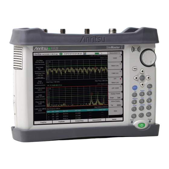
Site Master
Cable and Antenna Analyzer
with Spectrum Analyzer
S331E, 2 MHz to 4 GHz
S332E, 2 MHz to 4 GHz, Spectrum Analyzer, 100 kHz to 4 GHz
S361E, 2 MHz to 6 GHz
S362E, 2 MHz to 6 GHz, Spectrum Analyzer, 100 kHz to 6 GHz
Appendix A provides a list of supplemental documentation for the
Site Master features and options. The documentation set is
available as PDF files on the documentation disc and the
Anritsu website.
Anritsu Company
490 Jarvis Drive
Morgan Hill, CA 95037-2809
USA
http://www.anritsu.com
Part Number: 10580-00252
Revision: K
Published: March 2016
Copyright 2016 Anritsu Company
Advertisement
Table of Contents

Related Manuals for Anritsu S331E


Summary of Contents for Anritsu S331E
- Page 1 Site Master Cable and Antenna Analyzer with Spectrum Analyzer S331E, 2 MHz to 4 GHz S332E, 2 MHz to 4 GHz, Spectrum Analyzer, 100 kHz to 4 GHz S361E, 2 MHz to 6 GHz S362E, 2 MHz to 6 GHz, Spectrum Analyzer, 100 kHz to 6 GHz Appendix A provides a list of supplemental documentation for the Site Master features and options.
-
Page 3: Table Of Contents
Additional Documentation ........1-1 Contacting Anritsu for Sales and Service ..... . . 1-2 Instrument Description . - Page 4 Table of Contents (Continued) Tilt Bail Stand ..........2-21 Chapter 3—Quick Start Guide Introduction .
- Page 5 Anritsu Software Tool Box ........
- Page 6 Table of Contents (Continued) Software Tools ..........8-3 Line Sweep Tools (LST) .
-
Page 7: Chapter 1-General Information
Read the Handheld Instruments Product Information, Compliance, and Safety Guide (PN: 10100-00065) for important safety, legal, and regulatory notices before operating the equipment. For additional information and literature covering your product, visit the product page of your instrument and select the Library tab: • http://www.anritsu.com/en-US/test-measurement/products/s331e • http://www.anritsu.com/en-US/test-measurement/products/s332e • http://www.anritsu.com/en-US/test-measurement/products/s361e •... -
Page 8: Contacting Anritsu For Sales And Service
The bright 8.4 in TFT color display provides easy viewing in a variety of lighting conditions. All Site Master models are equipped with a Li-Ion battery delivering more than four hours of battery life for the S331E/S361E and more than three hours of battery life for the S332E/S362E Site Masters. -
Page 9: Available Options
The Cable and Antenna Analyzer mode requires calibration standards for OPEN, SHORT, and LOAD (OSL) or InstaCal module, which are sold separately. Anritsu recommends allowing the instrument to warm up to typical operation Note temperature (approximately 15 minutes) before calibrating. -
Page 10: Instrument Care And Preventive Maintenance
1-4 Instrument Care and Preventive Maintenance General Information Instrument Care and Preventive Maintenance Instrument care and preventive maintenance consist of cleaning the unit and inspecting and cleaning the RF connectors and all accessories. Clean the instrument with a soft, lint-free cloth dampened with water or water and a mild cleaning solution. -
Page 11: Esd Caution
General Information 1-4 Instrument Care and Preventive Maintenance ESD Caution The Site Master, like other high performance instruments, is susceptible to electrostatic discharge (ESD) damage. Coaxial cables and antennas often build up a static charge, which (if allowed to discharge by connecting directly to the instrument without discharging the static charge) may damage the Site Master input circuitry. - Page 12 Site Master with the optional Dual Battery Charger. Refer to “Symbols and Indicators” on page 2-9 for a description of battery symbols. Use only Anritsu Company approved batteries, adapters, and chargers with this Note instrument. Anritsu recommends removing the battery for long-term storage of the instrument.
-
Page 13: Secure Environment Workplace
General Information 1-5 Secure Environment Workplace Secure Environment Workplace This section details the types of memory in the Site Master, how to delete stored user files in internal memory, and recommended usage in a secure environment workplace. Site Master Memory Types The instrument contains non-volatile disk-on-a-chip memory, EEPROM, and volatile DRAM memory. - Page 14 1-5 Secure Environment Workplace General Information 3. Press the Save submenu key. 4. Press the Change Save Location submenu key, then select the USB drive with the rotary knob, Up/Down arrow keys, or the touch screen. 5. Press the Set Location submenu key. The external USB drive is now the default location for saving files.
-
Page 15: Chapter 2-Instrument Overview
The Site Master can also be operated from a 12 VDC source (which will simultaneously charge the battery). This can be achieved with either the Anritsu AC-DC Adapter or the Automotive Power Adapter. Both items are included as standard accessories with the Site Master. -
Page 16: Instrument Front Panel
2-3 Instrument Front Panel Instrument Overview Instrument Front Panel The Site Master uses a touch screen and keypad for data input. See Figure 2-1. The five bottom menu keys and up to eight submenu keys on the right side of the display are touch screen keys. -
Page 17: Front Panel Keys
Instrument Overview 2-3 Instrument Front Panel Front Panel Keys The numeric keypad, rotary knob, and the four arrow keys can all be used to change the value of the currently selected parameter. Numeric Keypad Keys 0 through 9 are used for numeric input, with an alternate function printed in blue above each of the keys. - Page 18 2-3 Instrument Front Panel Instrument Overview Menu Key The Menu key displays a grid of shortcut icons for installed measurement modes and user-selected menus and setup files. See Figure 2-3. Press one of the icons in the top three rows to change modes. These icons are preinstalled and cannot be moved or deleted. An alternative to the Menu key is to press Shift, then the Mode (9) key to display the Mode Selector list box.
- Page 19 Instrument Overview 2-3 Instrument Front Panel User-Created Shortcuts To create a shortcut to any submenu key or main menu key, press and hold the key until a grid appears, showing the open locations on the Menu screen where you can place the new shortcut.
-
Page 20: Interface Screen
2-4 Interface Screen Instrument Overview Interface Screen Figure 2-6 Figure 2-7 illustrate the Site Master interface screen in Cable and Antenna mode and Spectrum Analyzer mode, with touch screen menu keys, title bar, and measurement settings and results around the graph area, or sweep window. Figure 2-6. - Page 21 Instrument Overview 2-4 Interface Screen Figure 2-7. Spectrum Analyzer Display (S332E and S362E only) Measurement Settings Summary (Touch Screen Shortcuts) Frequency Standard Date and Time GPS Icon GPS Location Save Icon Save Screen Icon Battery Charge Indicator Trace Measurement Title Submenu Touch Screen Keys Main Menu Touch Screen Keys Marker Table...
-
Page 22: Touch Screen Keys
Use only Anritsu-approved batteries, adapters, and chargers with this instrument. Caution Anritsu Company recommends removing the battery for long-term storage of the instrument. The Shift key icon is displayed after the Shift key is pressed, and it remains displayed until another button is pressed. -
Page 23: Symbols And Indicators
Instrument Overview 2-4 Interface Screen Symbols and Indicators The following symbols, icons, and indicators convey the instrument status or condition on the display. The colors shown here are in the standard or default display mode. Table 2-1. Symbols and Icons Symbol Description Green: Battery is 30% to 100% charged. -
Page 24: Display Settings
2-4 Interface Screen Instrument Overview Display Settings The Display Settings submenu lets you adjust the screen brightness level and control the auto-dimming function. Refer to “Brightness Settings Menu” on page 5-8. You can also turn off the display entirely, as described in “Display Settings Menu”... -
Page 25: Touch Screen Calibration
Instrument Overview 2-4 Interface Screen Touch Screen Calibration Calibration optimizes the response of touch input. It is recommended if the instrument does not respond as expected when you press the touch screen. The Calibrate Touch Screen submenu key is in the “System Menu”... - Page 26 *.spa measurement file. To return to normal touch entry mode, reboot the instrument (turn power Off, then On). If your touch screen has been damaged, refer to “Contacting Anritsu for Sales and Service” on page 1-2. Figure 2-12. Arrow Navigation Example 2-12 PN: 10580-00252 Rev.
-
Page 27: Calibration Symbols
Instrument Overview 2-4 Interface Screen Calibration Symbols The current calibration status and type is displayed in the upper-left of the screen when in Cable & Antenna Analyzer mode. See Figure 2-6 on page 2-6. The five status messages are described next. Cal Status: ON, Flex The Site Master has been calibrated with discrete Open, Short, and Load components. -
Page 28: Data Entry
2-5 Data Entry Instrument Overview Data Entry User input can be in the form of numeric values for instrument or measurement settings, selected values from a preset list, or alphanumeric text when entering file names, for example. To view or change a parameter value, access the appropriate submenu by pressing one of the five main menu keys along the bottom of the interface screen, then navigating through the touch screen submenus. -
Page 29: Text Entry
Instrument Overview 2-5 Data Entry Text Entry When an instrument function requires you to enter text, such as a name for a measurement or setup file you wish to save, a touch screen keyboard is displayed. See Figure 2-13. Digits can be entered using the touch screen keyboard or the front panel keypad. -
Page 30: Mode Selector
2-6 Mode Selector Instrument Overview Mode Selector To change to another operation or measurement mode, press Shift, then the Mode (9) key to display the Mode Selector list box, illustrated in Figure 2-14. Use the directional arrow keys or the rotary knob to highlight the desired mode, then press Enter to switch to the selected application. -
Page 31: Connector Panel
Instrument Overview 2-7 Connector Panel Connector Panel The Site Master S332E connector panel is illustrated in Figure 2-15. Figure 2-15. S332E Connector Panel External Reference In External Trigger In Analyzer/RF In (Type N) USB Mini-B GPS Type SMA (Option 31) External Power USB Type A Headset jack... - Page 32 Site Master is connected to a PC, the normal USB device detection by the computer operating system will take place. For proper detection, the applicable Anritsu Software Tool should be installed on Note the PC prior to connecting the Site Master to the USB port.
- Page 33 Instrument Overview 2-7 Connector Panel External Power This is a 2.1 mm by 5.5 mm barrel connector, 12.5 to 15 VDC, < 4.0 A. The external power connector is used to power the unit and for battery charging. A green blinking LED near the Power button indicates that the instrument battery is being charged by the external charging unit.
-
Page 34: Soft Carrying Case
2-8 Soft Carrying Case Instrument Overview Soft Carrying Case The Site Master can be operated while in the soft carrying case. On the back of the case is a large storage pouch for accessories and supplies. To install the instrument into the soft carrying case: 1. -
Page 35: Tilt Bail Stand
Instrument Overview 2-9 Tilt Bail Stand The soft carrying case includes a detachable shoulder strap, which can be connected to the D-rings of the case. The soft case has panel openings for the fan inlet and exhaust ports. Do not block Caution the air flow through the panels when the unit is operating. - Page 36 2-9 Tilt Bail Stand Instrument Overview 2-22 PN: 10580-00252 Rev. K Site Master User Guide...
-
Page 37: Chapter 3-Quick Start Guide
Chapter 3 — Quick Start Guide Introduction This chapter provides a brief overview of basic setups for the following measurement modes: • “Cable & Antenna Analyzer” on page 3-2 • “Spectrum Analyzer” on page 3-7 For detailed descriptions of measurement functions and settings, refer to the appropriate Measurement Guide as listed in Appendix Measurement Mode Selection... -
Page 38: Cable & Antenna Analyzer
3-3 Cable & Antenna Analyzer Quick Start Guide Cable & Antenna Analyzer Set the instrument to Cable & Antenna Analyzer mode as described in the previous section. Select the Measurement Type Press the Measurement main menu key and select the appropriate measurement. Figure 3-2. -
Page 39: Turn On Markers
Quick Start Guide 3-3 Cable & Antenna Analyzer Turn on Markers 1. Press the Marker main menu key. 2. Press the Marker 1 2 3 4 5 6 submenu key and select the marker number 1 button using the touch screen. The underlined number on the Marker submenu key indicates the active marker. -
Page 40: Single Limit Line
3-3 Cable & Antenna Analyzer Quick Start Guide Single Limit Line 1. Press Shift, then Limit (6) to display the Limit menu. 2. Press the Limit On/Off key to turn on the Limit. 3. Press Single Limit and then use the numeric keypad, the arrow keys, or the rotary knob to change the limit value and then press Enter. -
Page 41: Dtf Setup
Quick Start Guide 3-3 Cable & Antenna Analyzer DTF Setup 1. Press the Measurements main menu key and select DTF Return Loss or DTF VSWR. 2. Press the Freq/Dist main menu key. 3. Press the Units submenu key and select m to display distance in meters or ft to display distance in feet. -
Page 42: Calibrate With Osl Calibration
3-3 Cable & Antenna Analyzer Quick Start Guide Calibrate with OSL Calibration Refer to the Cable & Antenna Measurement Guide listed in Appendix A Note calibration details. 1. Press the Freq/Dist main menu key and enter the appropriate frequency range 2. -
Page 43: Spectrum Analyzer
Quick Start Guide 3-4 Spectrum Analyzer Spectrum Analyzer Set the instrument to Spectrum Analyzer mode as described in Section “For detailed descriptions of measurement functions and settings, refer to the appropriate Measurement Guide as listed in Appendix A.” on page 3-1. -
Page 44: Set The Amplitude
3-4 Spectrum Analyzer Quick Start Guide Set the Amplitude Press the Amplitude main menu key to display the Amplitude menu. Set Amplitude Reference Level and Scale 1. Press the Reference Level submenu key and use the arrow keys, rotary knob, or the keypad to change the reference level. -
Page 45: Single Limit Line
Quick Start Guide 3-4 Spectrum Analyzer Single Limit Line Press the Limit menu key to display the Limit menu. 1. Press the Limit (Upper / Lower) submenu key to select the desired limit line, Upper or Lower. 2. Activate the selected limit line by pressing the On Off submenu key so that On is underlined. -
Page 46: Setting Up Markers
3-4 Spectrum Analyzer Quick Start Guide Setting Up Markers Press the Marker main menu key to display the Marker menu. Selecting, Activating, and Placing a Marker 1. Press the Marker 1 2 3 4 5 6 submenu key and select the desired marker using the touch screen marker buttons. -
Page 47: Select A Measurement Type
Quick Start Guide 3-4 Spectrum Analyzer Select a Measurement Type In Spectrum Analyzer mode, press Shift, then Measure (4) and select a measurement using the submenu keys. Figure 3-8. Spectrum Analyzer Measure Menu External Power On The When DC Applied setting in the Power-On menu allows the Site Master to restart automatically when external DC power is applied to the connector shown in Figure 2-15 on page... - Page 48 3-4 Spectrum Analyzer Quick Start Guide 3-12 PN: 10580-00252 Rev. K Site Master User Guide...
-
Page 49: Chapter 4-File Management
Chapter 4 — File Management Introduction This chapter describes the file management features of the Site Master and the related touch screen menus. The File menu and its submenus allow you to save, recall, copy, and delete files in internal memory or an external USB flash drive. Managing Files Press the Shift key, then the File (7) key on the numeric keypad to display the File menu. -
Page 50: Save Files
4-2 Managing Files File Management Save Files The submenu keys that are available for file management may vary with instrument options and measurement modes. Refer to “File Menu” on page 4-10. Save Measurement As The Save Measurement As submenu key provides a one-touch method of saving the current measurement data. - Page 51 File Management 4-2 Managing Files Save Dialog Box In the Save dialog, use the touch screen keyboard to enter the name of the file to save. See Figure 4-1 on page 4-2. Optionally, you can use the Quick Name keys to insert preset text strings into the file name.
- Page 52 4-2 Managing Files File Management Quick Name Matrix The Quick Name Matrix key is present in the Save dialog only in the Cable and Antenna Analyzer measurement mode. See Figure 4-4. Similarly to the Quick Name keys, the matrix gives field personnel a shortcut method to enter file names in compliance with carrier requirements, which may include file naming conventions related to site number, sector information, color coding, measurement type, termination device, or frequency information.
- Page 53 File Management 4-2 Managing Files Follow these steps to define and use shortcut keys in the Quick Name Matrix. If all matrix keys are already defined, proceed directly to Step 1. To edit any matrix key, press and hold the key until the Edit Quick Name dialog opens. Figure 4-3 on page 4-3.
-
Page 54: Recall Files
4-2 Managing Files File Management Use the touch screen, the Up/Down arrow keys, or the rotary knob to select a folder from the list. To expand a folder and view its subfolders, press Enter or the Right arrow key. Press Enter again or the Left arrow key to collapse the folder. -
Page 55: Copy Files
File Management 4-2 Managing Files Copy Files Press the Copy key under the File menu to open the Copy dialog box and menu, where you can copy a single or multiple files or folders. The source and destination locations may be the instrument’s internal memory or an external USB drive, if connected. -
Page 56: Delete Files
4-2 Managing Files File Management 8. Press the Scroll key to switch navigation control to the Dst (destination) pane. Alternatively, you can directly press a folder in the bottom pane to select it. 9. If the destination folder is off the screen, use the rotary knob or the Up/Down arrow keys to locate and select it. -
Page 57: File Menu Overview
File Management 4-3 File Menu Overview File Menu Overview Open this menu by pressing the Shift key, then the File (7) key. File Save Measurement As FileName_1.spa Save Save Measurement Equivalent to pressing the screen shortcut Save Restore Default Quick Spectrum Save Name Buttons... -
Page 58: File Menu
4-4 File Menu File Management File Menu Key Sequence: Shift > File (7) Save Measurement As: Pressing this key will save instrument setup parameters, trace data, and any measurement results to the file that is named File on the submenu key. Upon Save completion, the file name numerical suffix Save Measurement As increments by 1 and will be applied to the next Save. -
Page 59: Save Menu
File Management 4-4 File Menu Save Menu Key Sequence: Shift > File (7) > Save Measurement Key Sequence: Shift > File (7) > Save Save Restore Default Quick Name Buttons: Press this submenu key to undo any Quick Names previously entered and return all Quick Name buttons to Restore factory defaults. -
Page 60: File Type Menu
4-4 File Menu File Management File Type Menu Key Sequence: Shift > File (7) > Save Measurement > Change Type Key Sequence: Shift > File (7) > Save > Change Type File Type JPEG Capture Full Graph Only: Press this submenu key to toggle between file types, Full JPEG Capture and Graph Only. -
Page 61: Save On
File Management 4-4 File Menu Save On... Menu Key Sequence: Shift > File (7) > Save On Event In Spectrum Analyzer mode, this menu is used to automatically save measurements to the current save location after any of the following events: Save On... -
Page 62: Recall Menu
4-4 File Menu File Management Recall Menu Key Sequence: Shift > File (7) > Recall Recall Sort By Sort By Name Type Date: Press this submenu key to choose the item by which folders and files are sorted in the Recall dialog box. See Figure 4-7 Name Type... -
Page 63: Copy Menu
File Management 4-4 File Menu Copy Menu Key Sequence: Shift > File (7) > Copy Copy Sort By Name Type Date: Press this submenu key to choose the item by which Sort By folders and files are sorted in the Copy dialog box. See Figure 4-8 Name Type... -
Page 64: Delete Menu
4-4 File Menu File Management Delete Menu Key Sequence: Shift > File (7) > Delete Delete Sort By Sort By Name Type Date: Press this submenu key to choose the item by which folders and files are sorted in the Delete dialog box. See Figure 4-9 Name Type... -
Page 65: Chapter 5-System Operations
Chapter 5 — System Operations Introduction This chapter reviews the Site Master system operations and related menus. The other menus (Sweep, Measure, Trace, and Limit) are described in the Measurement Guides listed in Appendix Site Master User Guide PN: 10580-00252 Rev. K... -
Page 66: System Menu Overview
5-2 System Menu Overview System Operations System Menu Overview To access the System menu functions, press the Shift key, then the System (8) key. System System Options Display Settings Brightness Settings Date Status & Brightness Brightness Time Self Ethernet Auto Dim GPS Info Display Blank Test... -
Page 67: System Menu
Application If the self test fails when the battery is fully charged and the instrument is Self within the specified operating temperature, contact your Anritsu Service Test Center and report the test results. Application Self Test: This key initiates a series of diagnostic tests related to the performance of the instrument for specific applications. -
Page 68: System Options Menu
5-3 System Menu System Operations System Options Menu Key Sequence: Shift, System (8) > System Options Date and Time: Press this submenu key to display a dialog box for setting System Options the current date and time. Use the submenu keys or the Left/Right arrow keys to select the field to be modified. -
Page 69: System Options 2/2 Menu
System Operations 5-3 System Menu System Options 2/2 Menu Key Sequence: Shift, System (8) > System Options > More Share CF & Pwr Offset All Modes Not Shared: Press this submenu key to toggle the setting System Options 2/2 between All Modes and Not Shared. Select All Modes to have the current Share CF &... -
Page 70: Power-On Menu
5-3 System Menu System Operations Figure 5-5. Remote Access Password Dialog Power-On Menu Key Sequence: Shift, System (8) > System Options > More > Power–On Power–On Power Switch: Press this submenu key to set the instrument for normal use Power Switch of the On/Off button on the instrument front panel. -
Page 71: Display Settings Menu
System Operations 5-3 System Menu Display Settings Menu Key Sequence: Shift, System (8) > System Options > Display Brightness: Opens the “Brightness Settings Menu” on page 5-8. Display Settings Display Blank: Opens the message box illustrated in Figure 5-8. Press Enter to turn off the display, or press Esc to abort. -
Page 72: Brightness Settings Menu
5-3 System Menu System Operations Brightness Settings Menu Key Sequence: Shift, System (8) > System Options > Display > Brightness The brightness of the display can be adjusted to optimize viewing under a wide variety of lighting conditions. Brightness Settings Brightness: Press this submenu key to open the Brightness Editor window, where you can adjust the display brightness level from 0 to 100, with 100 Brightness... -
Page 73: Reset Menu
System Operations 5-3 System Menu Reset Menu Key Sequence: Shift, System (8) > System Options > Reset Factory Defaults: Press this submenu key to restore the instrument to its Reset factory default settings, including Ethernet (Option 411), language, volume, and brightness settings. The instrument will power cycle as part of this Factory operation. -
Page 74: Preset Menu
If the Site Master is within the specified operating range with a charged battery and the self test fails, contact your Anritsu Service Center at http://www.anritsu.com/contact-us. To initiate a self test when the system is already powered up: 1. -
Page 75: Updating The Site Master Firmware
Updating the Site Master Firmware The Site Master is updated using a USB memory stick. Updated product information can be found on the Anritsu website: http://www.anritsu.com/en-US/test-measurement/rf-microwave/cable-and-antenna-analyzers Search for the product model number and click the link. On the product page, press the Downloads link, then click the Drivers/Firmware/Software tab. - Page 76 5-6 Updating the Site Master Firmware System Operations 5-12 PN: 10580-00252 Rev. K Site Master User Guide...
-
Page 77: Chapter 6-Gps (Option 31)
Chapter 6 — GPS (Option 31) Introduction The Site Master is available with a built-in GPS receiver feature (Option 31) that can provide latitude, longitude, altitude, and UTC timing information. This option also enhances frequency reference oscillator accuracy in the spectrum analyzer mode. When GPS is actively locked to satellites, this information is saved with all saved measurements and can be displayed with Master Software Tools. - Page 78 6-2 Activating the GPS Feature GPS (Option 31) 4. When the GPS receiver is tracking at least four satellites, the GPS icon changes to green. Latitude and longitude information is displayed in the title bar at the top of the display.
-
Page 79: Resetting Gps
GPS (Option 31) 6-3 Resetting GPS Resetting GPS To reset the GPS, press the Reset submenu key. The green GPS icon shows a red cross mark when satellite tracking is lost after tracking four or more satellites. The GPS latitude and longitude are saved in the instrument memory until the Site Master is turned off or until GPS is turned off by using the GPS On/Off key. -
Page 80: Gps Menu
Short/Open: If an active antenna is in use, a short or open exists between the antenna and the connection. If this message is displayed, replace the antenna. If the message persists, try another Anritsu GPS antenna. If needed, contact your nearest Anritsu Service Center. If a passive antenna is in use, the message should display: Antenna OPEN Detected or Passive Antenna Used. -
Page 81: Chapter 7-Bias Tee (Option 10)
Chapter 7 — Bias Tee (Option 10) Overview Option 10 provides a bias tee that is installed inside the instrument. The bias arm is connected to a 12 VDC to 32 VDC power source that can be turned on as needed to place the voltage on the center conductor of the instrument’s RF In port. - Page 82 7-1 Overview Bias Tee (Option 10) PN: 10580-00252 Rev. K Site Master User Guide...
-
Page 83: Chapter 8-Anritsu Tool Box
Chapter 8 — Anritsu Tool Box Introduction The Anritsu Tool Box is a suite of applications that provide an interface between Anritsu handheld RF instruments and a PC. The instrument connects to the computer via a USB, Ethernet, or serial port. Depending on the application selected, available functions range... -
Page 84: Anritsu Software Tool Box
Tool Box Installer on the Anritsu Software DVD Anritsu Software Tool Box The Anritsu Tool Box serves as a central location from which you can open a previously saved measurement, visit the Anritsu website, or launch an application. To open the Tool Box, either double-click the desktop shortcut or select the Tool Box from the Windows Start menu, under All Programs and the Anritsu folder. -
Page 85: Software Tools
Windows Start menu. The following sections list the top features and functions of the tools contained in the Anritsu Tool Box. For a detailed description of these features and how to perform specific tasks, refer to each application’s Help system. -
Page 86: Easytest Tools
Tools easyMap Tools is the new name for Anritsu Map Master. The application allows users to find and prepare geo-referenced maps and to build floor plans suitable for Anritsu Handheld Spectrum Analyzers with Interference Analysis or Coverage Mapping capabilities (Option 25 or Option 431, respectively). -
Page 87: Chapter 9-Web Remote Control
Chapter 9 — Web Remote Control Introduction Web Remote Control capabilities are embedded in the Site Master, providing full instrument control through an HTML-5 compatible browser. Ethernet Option 411 is required. The ability to remotely monitor and control the instrument from the ground or desk enhances operator safety and efficiency when conditions make it unsafe or impractical to be close to the instrument. -
Page 88: Connection To A Wi-Fi Portable Router
9-2 Setup Web Remote Control Alternatively, you can set the instrument for dynamic IP addressing using DHCP. In a long distance network, however, it may be difficult or impossible to determine what the current dynamic address is, after the instrument is in the field. 5. - Page 89 Web Remote Control 9-2 Setup Figure 9-1. Setting IP Address Manually Site Master User Guide PN: 10580-00252 Rev. K...
-
Page 90: Web Remote Control Interface
9-3 Web Remote Control Interface Web Remote Control Web Remote Control Interface After you have entered the instrument IP address in a Web browser’s address bar, the Web Remote Control login page opens if this is the first time you are connecting to the instrument, or if a password is required and you previously logged out. - Page 91 Web Remote Control 9-3 Web Remote Control Interface At the top of the browser window, a green title bar shows the instrument model number and IP address. If the instrument has been assigned a name, this name is displayed in the center of the title bar.
-
Page 92: Menu Bar
9-3 Web Remote Control Interface Web Remote Control Menu Bar Remote Control Opens “Remote Control” on page 9-7. Capture Screen Captures a JPEG image of the instrument display and saves it directly to internal memory. A file name is automatically created using the current date and time stamp. Only the instrument display will be pictured on the Web page under the menu bar. -
Page 93: Remote Control
Web Remote Control 9-3 Web Remote Control Interface Depending on the browser and operating system used, different prompts may appear. Some operating systems like iOS may not support file saving from a browser. File List Displays the list of folders and files contained in the instrument's internal memory. You can select from the list the files or folders you wish to download to your PC or mobile device. - Page 94 9-3 Web Remote Control Interface Web Remote Control Normal Mode Normal Mode is the default mode, where the bitmap image of the instrument screen is continually refreshed in the browser window. Click the single arrow button at the bottom right of the screen or any tab on the menu bar to return to Normal Mode from either Fast or Pause Mode.
-
Page 95: File List
Web Remote Control 9-3 Web Remote Control Interface File List Displays the list of folders (type “dir”) and files contained in the instrument's internal memory. See Figure 9-7. To view the contents of a folder, click on the folder name. Figure 9-7. -
Page 96: Device Management
9-3 Web Remote Control Interface Web Remote Control If the selected item is a single file, the file will open in the default application for the file type. For example, a JPEG file will open in the computer's default image viewer, while a measurement file will open in Master Software Tools (MST), provided the application is installed. -
Page 97: Logout
Web Remote Control 9-3 Web Remote Control Interface The login page is skipped and the user is directed straight to the Web Remote Control Home page if he or she was previously connected to the instrument, then closed the browser without logging out, and no other user has logged in to the same instrument since that time. - Page 98 9-3 Web Remote Control Interface Web Remote Control 9-12 PN: 10580-00252 Rev. K Site Master User Guide...
-
Page 99: Appendix A-Measurement Guides
Appendix A — Measurement Guides Introduction This appendix provides a list of supplemental documentation for Site Master features and options. These manuals are available as PDF files on the documentation disc and the Anritsu website. Table A-1. Analyzers and Analyzer Options... - Page 100 A-1 Introduction Measurement Guides PN: 10580-00252 Rev. K Site Master User Guide...
-
Page 101: Lan Connection
Appendix B — LAN and DHCP Introduction This appendix describes network connections for the Site Master. LAN Connection The RJ-45 connector is used to connect the Site Master to a local area network. Integrated into this connector are two LEDs. The amber LED shows the presence of a 10 Mbit/s LAN connection when on, and a 100 Mbit/s LAN connection when off. -
Page 102: B-3 Ethernet Configuration
B-3 Ethernet Configuration LAN and DHCP Ethernet Menu Key Sequence: Shift, System (8) > System Options > Ethernet Config Type Manual DHCP: Press the Type submenu key to select whether the IP Ethernet address will be entered manually or will be supplied automatically by a Type network DHCP server. - Page 103 LAN and DHCP B-3 Ethernet Configuration Figure B-2. Setting IP Address Manually Figure B-3. IP Address Assigned Using DHCP Site Master User Guide PN: 10580-00252 Rev. K...
-
Page 104: Dhcp
B-3 Ethernet Configuration LAN and DHCP DHCP DHCP stands for Dynamic Host Configuration Protocol. It is a protocol that allows a server to dynamically assign IP addresses to devices that are connected to the network. Most networks include a DHCP server to manage IP addresses. When using DHCP, no setup is required to lease and use a dynamic IP address. -
Page 105: B-4 Ipconfig Tool
Windows 2000 IP Configuration Ethernet adapter Local Area Connection: Connection-specific DNS Suffix. : us.anritsu.com IP Address... . : 172.26.202.172 Subnet Mask ... : 255.255.252.0 Default Gateway . -
Page 106: Ping Tool
B-5 Ping Tool LAN and DHCP Ping Tool Another tool that can find out if a selected IP address is already on the network is ping. Ping is a harmless way to determine if an address is found on the network, and (if it is found) to receive a reply. -
Page 107: Glossary
Appendix C — Glossary of Terms Introduction The following terms are related to this product and technology. Glossary 3 dB rule : The 3 dB rule provides a means to estimate relative power values. A 3 dB gain indicates that power increases to twice the power (a multiple of 2). - Page 108 C-2 Glossary Glossary of Terms Antenna : Antenna is a device which radiates and/or receives radio signals, including RF, microwave, and RADAR. Antenna beamwidth : Antenna beamwidth, also known as the half-power beamwidth, is the angle of an antenna pattern or beam over which the relative power is at or above 50% of the peak power.
- Page 109 Glossary of Terms C-2 Glossary Average power : Average power is the peak power averaged over time and is usually applied to pulsed systems where the carrier power is switched on and off. Backhaul : In wireless technology, backhaul refers to transporting voice and data traffic from a cell site to the switch.
- Page 110 Calibration : When making measurements, the instrument must be calibrated in order to remove residual errors due to measurement setup conditions. Anritsu recommends performing the calibration under the same conditions as the measurement: temperature, frequency, number of points, source power, and IFBW. Calibrations standards with known reflection coefficients are used to calculate the correction factors.
- Page 111 Glossary of Terms C-2 Glossary Cellular : In wireless communications, cellular refers most basically to the structure of the wireless transmission networks which are comprised of cells or transmission sites. Cellular is also the name of the wireless telephone system originally developed by Bell Laboratories that used low-powered analog radio equipment to transmit within cells.
- Page 112 C-2 Glossary Glossary of Terms DANL : Displayed Average Noise Level (DANL): Displayed average noise level is sometimes confused with the term Sensitivity. While related, these terms have different meanings. Sensitivity is a measure of the minimum signal level that yields a defined signal-to-noise ratio (SNR) or bit error rate (BER).
- Page 113 Glossary of Terms C-2 Glossary dBm : dBm is an absolute measurement of power relative to 1 milliwatt. In other words, dBm is a decibel value referenced to a milliWatt (dBm). This is a technique for expressing a power measurement in logarithmic form using 1 mW as a reference.
- Page 114 C-2 Glossary Glossary of Terms DVB-S : Digital Video Broadcasting-Satellite (DVB-S) is the original Digital Video Broadcasting (DVB) forward error coding and modulation standard for satellite television and dates from 1995. It is used via satellites serving every continent of the world. DVB-S is used in both MCPC and SCPC modes for broadcast network feeds, as well as for direct broadcast satellite services like Sky TV (UK) via Astra in Europe, Dish Network in the U.S., and Bell ExpressVu in Canada.
- Page 115 Glossary of Terms C-2 Glossary FM Threshold : FM Threshold is the point at which the input signal power is just strong enough to enable the receiver demodulator circuitry to successfully detect and recover a good quality television picture from the incoming video carrier.
- Page 116 LRL : Line Reflect Line (LRL, also called TRL) method of calibration developed by Anritsu. LRL uses two (or more) transmission lines and a reflect standard (for each port). The line lengths are important because...
- Page 117 Glossary of Terms C-2 Glossary LRM : Line Reflect Match (LRM) method of calibration developed by Anritsu. In LRM, one of the lines of the LRL method is replaced with a match (or load). For basic LRM, the match is assumed to be perfect, and thus represents a line of infinite length.
- Page 118 C-2 Glossary Glossary of Terms OSLT : OSLT or Open Short Load Thru calibration method for coaxial line types. Calibrations standards with known reflection coefficients are used to calculate the correction factors. Refer to Calibration. Compare this with SSLT or Offset Short 1, Offset Short 2, Load, Thru calibration method for waveguide line types.
- Page 119 Glossary of Terms C-2 Glossary Signal loss : Signal loss is the amount of signal strength that is lost in antenna cable, connectors, and free space. Signal loss is measured in decibels. Smith Chart : A Smith Chart is a graphical aid for electrical and electronics characteristics in radio frequency (RF) circuits.
- Page 120 C-2 Glossary Glossary of Terms TMA : A Tower Mounted Amplifier (TMA) amplifies signals from an antenna to reduce the signal to noise ratio of a base transceiver station (BTS). This helps to improve the overall sensitivity of the BTS. A TMA is a low-noise amplifier (LNA) that is usually mounted as close as practical to the antenna in Base Transceiver Stations or in mobile masts.
-
Page 121: Index
Anritsu ....1-2 updating ....5-9, 5-11 copy menu . - Page 122 ... . 2-19 links contacting Anritsu ... . . 1-2 password product page ....5-11 remote .
- Page 123 IP address ..B-4 website, contacting Anritsu ..1-2 system menu ..... 5-2 Wi-Fi router .
- Page 124 Index-4 PN: 10580-00252 Rev. K Site Master User Guide...
- Page 126 Anritsu Company 490 Jarvis Drive Anritsu utilizes recycled paper and environmentally conscious inks and toner. Morgan Hill, CA 95037-2809 http://www.anritsu.com...
Need help?
Do you have a question about the S331E and is the answer not in the manual?
Questions and answers