Anritsu Site Master S332D User Manual
Cable and antenna analyzer
Hide thumbs
Also See for Site Master S332D:
- Programming manual (132 pages) ,
- Maintenance manual (52 pages)
Table of Contents
Advertisement
Quick Links
Site Master
S331D/S332D
Cable and Antenna Analyzer
Site Master is the preferred cable and antenna analyzer of
wireless providers, contractors and installers.
S331D
SiteMaster
Site Master
MS2712
SiteMaster
SpectrumMaster
Color display option shown
MS2711D
MT8212A
Spectrum Master
SpectrumMaster
MS2712
Cell Master
CellMaster
™
CellMaster
MS2712
User's Guide
Advertisement
Table of Contents

Subscribe to Our Youtube Channel
Related Manuals for Anritsu Site Master S332D


Summary of Contents for Anritsu Site Master S332D
- Page 1 Site Master ™ S331D/S332D Cable and Antenna Analyzer Site Master is the preferred cable and antenna analyzer of wireless providers, contractors and installers. Color display option shown S331D SiteMaster MS2711D MT8212A Site Master MS2712 Spectrum Master SpectrumMaster MS2712 Cell Master CellMaster MS2712 User’s Guide...
- Page 2 Anritsu Company. UPDATES Updates to this manual, if any, may be downloaded from the Anritsu internet site at: http://www.us.anritsu.com. October 2004 10580-00079 Copyright ã...
-
Page 4: Table Of Contents
Table of Contents Chapter 1 - General Information Introduction ........1-1 Description . - Page 5 Adjusting Markers ......3-15 Adjusting Limits ......3-16 Adjusting the Display Contrast .
- Page 6 Chapter 8 - E1 Measurements Introduction ........8-1 E1 Fundamentals .
-
Page 7: Chapter 1 - General Information
Chapter 1 General Information Introduction This chapter provides a description, performance specifications, optional accessories, pre- ventive maintenance, and calibration requirements for the Site Master™ models S331D and S332D. Throughout this manual, the term Site Master will refer to the S331D and S332D. Model Frequency Range S331D... -
Page 8: Printers
Chapter 1 General Information The following items are supplied with the basic hardware: Soft Carrying Case · Rechargeable Battery · AC-DC Adapter · Automotive Cigarette Lighter 12 Volt DC Adapter · Handheld Software Tools CDROM · Serial Interface Cable (null modem type) ·... -
Page 9: Optional Accessories
Chapter 1 General Information Optional Accessories Part Number Description 10580-00100 S33xD Programming Manual (available on disk or at www.us.anritsu.com) 10580-00101 S331D Maintenance Manual 10580-00102 S332D Maintenance Manual 760-229 Transit Case 633-27 Rechargeable Battery, NiMH 2000-1029 Battery Charger with universal power supply, NiMH only... -
Page 10: Performance Specifications
Chapter 1 General Information Performance Specifications Performance specifications are provided in Table 1-1. All specifications apply when cali- brated at ambient temperature after a five minute warm up. Typical values are given for ref- erence, and are not guaranteed. Table 1-1. Performance Specifications (1 of 5) Cable and Antenna Analyzer Frequency Range:... - Page 11 Chapter 1 General Information Table 1-1. Performance Specifications (2 of 5) Spectrum Analyzer (S332D only) Frequency Range: 100 kHz to 3000 MHz (tunable to 9 kHz) Frequency Reference (internal timebase): Aging: ± 1 ppm/yr Accuracy: ± 2 ppm Frequency Span: 10 Hz to 2.99 GHz in 1, 2, 5 step selections in auto mode, plus zero span Sweep Time:...
- Page 12 Chapter 1 General Information Table 1-1. Performance Specifications (3 of 5) T1 Analyzer (Option 50, S331D only) Line Coding: AMI, B8ZS Framing Modes: D4 (Superframe), ESF (Extended Superframe) Connection Configurations: Terminate (100W) Bridge (³ 1000W) Monitor (Connect via 20 dB pad in DSX) Receiver Sensitivity: 0 to –36 dBdsx Transmit Level:...
- Page 13 Chapter 1 General Information Table 1-1. Performance Specifications (4 of 5) Loopback Modes: Self loopback Level Measurements: Vp-p (± 5%), dBdsx Data Log: Continuous, up to 48 hrs FCN4760 Frequency Converter (S332D only) Frequency Range 4.7 GHz to 6.0 GHz Frequency Resolution* 10 Hz Frequency Reference...
- Page 14 Chapter 1 General Information Table 1-1. Performance Specifications (5 of 5) Power Meter (Option 29) Frequency Range: 10 MHz to 3000 MHz Detection Range: –80 dBm to +80 dBm Offset Range: 0 to +60 dB Accuracy: ± 1 dB typical (± 1.5 dBm max), ³10 MHz to 3 GHz ±2 dB, typical, 3 MHz to <10 MHz VSWR: 1.5:1 typical (P...
-
Page 15: Preventive Maintenance
OSL calibration will cause uncompensated phase reflections inside the cable. Thus, cables which are NOT phase stable may cause measurement errors that are more pro- nounced as the test frequency increases. For optimum calibration, Anritsu recommends using precision calibration com- ponents. -
Page 16: Instacal Module
Chapter 1 General Information InstaCal Module The Anritsu InstaCal module can be used in place of discrete components to calibrate the Site Master. The InstaCal module can be used to perform an Open, Short and Load (OSL) or a FlexCal calibration procedure. Calibration of the Site Master with the InstaCal takes approximately 45 seconds (see Calibration, page 3-2). - Page 17 FAX: 82-2-553-6605 ANRITSU COMPANY 10 New Maple Ave., Unit 305 GERMANY SINGAPORE Pine Brook, NJ 07058 ANRITSU GmbH ANRITSU (SINGAPORE) PTE LTD. Telephone: (973) 227-8999 Grafenberger Allee 54-56 10, Hoe Chiang Road 1-800-ANRITSU D-40237 Dusseldorf, Germany #07-01/02 Keppel Towers FAX: 973-575-0092...
-
Page 18: Chapter 2 - Functions And Operations
The Site Master can also be powered by a 12.5 Vdc external source. The external source can be either the Anritsu AC-DC Adapter (P/N 40-163) or 12.5 Vdc Automotive Cigarette Lighter Adapter (P/N 806-62). Both items are standard accessories. - Page 19 Serial RS232 DB9 interface to a COM port on a personal computer (for use with the Interface Anritsu Handheld Software Tools program) or to a supported printer. RF Out/ RF output, 50 W impedance, for reflection measurements. Maximum input is Reflection 50W +23 dBm at ±50 Vdc.
-
Page 20: Display Overview
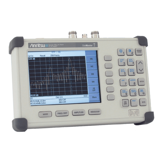
Chapter 2 Functions and Operations Display Overview Figure 2-2 illustrates some of the key information areas of the S331D display. TITLE BAR SWEEP DATA TIME POINTS CALIBRATION STATUS CURRENT MENU MESSAGE AREA Figure 2-2. S331D Display Overview Figure 2-3 illustrates some of the key information areas of the S332D display. TITLE BAR SWEEP MODE... -
Page 21: Front Panel Overview
Chapter 2 Functions and Operations Front Panel Overview The Site Master menu-driven user interface is easy to use and requires little training. Hard keys on the front panel are used to initiate function-specific menus. There are four function hard keys located below the status window: Mode, Frequency/Distance, Amplitude and Measure/Display. -
Page 22: Function Hard Keys
Chapter 2 Functions and Operations Function Hard Keys MODE Opens the mode selection box (below). Use the Up/Down arrow key to select a mode. Press the key to implement. ENTER o Measurement Mode Freq - SWR Return Loss Cable Loss - One Port DTF - SWR Return Loss Spectrum Analyzer... -
Page 23: Keypad Hard Keys
ENTER Implements the current action or parameter selection. Turns the Anritsu Site Master on or off. When turned on, the saved system state at the last turn-off is restored. If the ESCAPE/CLEAR key is held down while the ON/OFF key is pressed, the factory preset state will be restored. - Page 24 Chapter 2 Functions and Operations The following keypad hard key functions are printed in blue on the keypad keys. With the standard monochrome display, this key turns the liquid crystal display (LCD) back-lighting on or off. With the optional color display (Option 3), the backlight is always on, and this key is used to adust the backlight intensity only.
-
Page 25: Soft Keys
Chapter 2 Functions and Operations Soft Keys Each keypad key opens a set of soft key selections. Each of the soft keys has a correspond- ing soft key label area on the status window. The label identifies the function of the soft key for the current Mode selection. - Page 26 Chapter 2 Functions and Operations FREQ/DIST AMPLITUDE MEAS/DISP MODE=DTF: Resolu- SOFTKEYS: tion Single Bottom Sweep Trace DTF Aid Math Trace Overlay Fixed More On/Off Loss Select Trace Prop Cable List Window Page Up Page Back Down Back Bottom List Delete Trace Delete Traces...
- Page 27 Chapter 2 Functions and Operations FREQ/DIST MODE=SPECTRUM ANALYZER: AMPLITUDE SOFTKEYS: Center Level Span Scale Atten/ Start Preamp Edit Stop Auto Full Signal Units Standard Manual Zero Select Level Channel Span Offset Dynamic List 1-2-5 Span Page Up Down 1-2-5 Page Preamp dBmV Control...
- Page 28 Chapter 2 Functions and Operations On/Off Select Method Standard Antenna MODE = SPECTRUM ANALYZER: MEAS/DISP Select Center Custom Freq Antenna SOFTKEYS: Band- width Auto Channel Trace Manual Span Zoom Measure Measure Back Auto Channel Hold Trigger Back Measure Manual Field Detec- Strngth tion...
- Page 29 Chapter 2 Functions and Operations Auto Terminate D4 SF MODE=T1 Tester Bridged Monitor B8ZS +20 dB SOFTKEYS: BERT Setup Back BERT Start / Measure Back Stop BERT Measure Framing Mode Terminate/ Bridged Display Receive Raw Data/ Input Histogram Back Start / Pattern Stop Measure...
- Page 30 Chapter 2 Functions and Operations Auto Terminate PCM30 PCM30 Bridged MODE=E1 Tester Monitor HDB3 PCM31 +20 dB SOFTKEYS: BERT PCM31 Setup Back BERT Start / Measure Back Stop BERT Measure Framing Mode Terminate/ Bridged Display Receive Raw Data/ Input Histogram Back Start / Stop...
- Page 31 Chapter 2 Functions and Operations MODE = TRANSMISSION MEASUREMENT FREQ/SPAN AMPLITUDE BW/SWEEP SOFTKEYS: Band- Center width Level Calibrate Span Scale Auto Atten/ Start Preamp Hold Edit Manual Average Stop (2-25) Auto Full Auto Signal Standard Hold Manual Manual Select Channel Span Dynamic 1-2-5...
- Page 32 Chapter 2 Functions and Operations MODE=POWER METER: FREQ/DIST AMPLITUDE MEAS/DISP SOFTKEYS: Center Units Averaging Span Offset Edit Zero Full Medium Signal Standard High Select Span Channel 1-2-5 Span Back Down 1-2-5 Back Figure 2-13. Power Meter Mode Soft Key Labels (Option 29) Options Clock Units...
- Page 33 Self Test Change Hour Date Format Impedance External Minute Freq Status Bias Month Language English Anritsu 12N50-75B Other Back Adapter Year Offset Back Back Figure 2-15. SYS Key Menu in Spectrum Analyzer and Transmission Measurement Modes Options Clock Printer Self...
- Page 34 Chapter 2 Functions and Operations Options Clock Units Self Test Hour Printer Status Change Minute Date Format Month Data Language English Year Back Back Figure 2-17. SYS Key in T1/E1 Mode (Option 50) 2-17...
- Page 35 Chapter 2 Functions and Operations FREQ/DIST Displays the frequency and distance menu depending on the measurement mode. Frequency The frequency and distance menu for cable and antenna analyzer measurements Menu provides for setting sweep frequency end points when mode is selected. Se- Freq lected frequency values may be changed using the keypad or Up/Down arrow key.
- Page 36 Chapter 2 Functions and Operations — Returns to the Distance Menu. Back Choosing FREQ/DIST in Spectrum Analyzer mode causes the soft keys, below, to be dis- played and the corresponding values to be shown in the message area. ¾ Sets the center frequency of the Spectrum Analyzer. Enter a value Center using the Up/Down arrow key or keypad, press ENTER to accept, ESCAPE to restore previous value.
- Page 37 Chapter 2 Functions and Operations AMPLITUDE Displays the amplitude or scale menu depending on the measurement mode. Amplitude Provides for changing the status window scale. Selected values may be changed Menu using the Up/Down arrow key or keypad. Choosing in cable and antenna analyzer measurement modes AMPLITUDE causes the soft keys, below, to be displayed and the corresponding values to be shown in the message area.
- Page 38 Chapter 2 Functions and Operations MEAS/DISP Displays the Meas/Disp soft key menu for the current operating mode. Meas/Disp Provides for changing the status window resolution, single or continuous sweep, Menu and access to the Trace Math functions. Choosing MEAS/DISP in cable and antenna analyzer freq or DTF measurement modes causes the soft keys below to be displayed.
- Page 39 Chapter 2 Functions and Operations — The unit reads and displays the highest measured Positive Peak data point within a display point. — The unit reads and displays the RMS average of the RMS Average measured data. RMS average is calculated by taking the log of the av- erage power within a display point and the power is calculated from the voltage.
- Page 40 Chapter 2 Functions and Operations - Activates the center frequency function and sets the Site Center Freq Master to the center frequency. A specific center frequency can be en- tered using the keypad or Up/Down arrow key. — Enter the integration bandwidth frequency appropriate for Int BW the application.
- Page 41 Chapter 2 Functions and Operations — Opens carrier to interference measurement menu. - Opens a menu to select the signal type. Selections Signal Type are narrow band FHSS, wide band FHSS or a broadband signal. - Activates the center frequency function and sets the Site Center Master to the center frequency.
- Page 42 Chapter 2 Functions and Operations — Places the selected marker at the frequency or dis- Marker To Peak tance with the maximum amplitude value. — Places the selected marker at the frequency or dis- Marker To Valley tance with the minimum amplitude value. —...
- Page 43 Chapter 2 Functions and Operations — Returns to the Main Markers Menu. Back through — Selects the marker parameter and opens the marker second level menu. — Turns the selected marker on or off. On/Off — Opens the selected marker parameter for data entry. Press Edit ENTER when data entry is complete or ESCAPE to restore the previous value.
- Page 44 Chapter 2 Functions and Operations — Measures the signal level at the point of the marker in Regular Marker the unit type selected in the Amplitude - Units menu. When the regular marker option is selected, all markers are regular markers. —...
- Page 45 Chapter 2 Functions and Operations — Sets multiple user-defined upper limits, and can be Multiple Upper Limits used to create an upper limit mask for quick pass/fail measurements. An up- per limit will result in a failure when the data falls above the limit line. Menu choices are: —...
- Page 46 Chapter 2 Functions and Operations In cable and antenna analyzer or optional power meter mode, pressing the SYS key displays the following System menu soft key selections: — Displays a second level of functions: Options — Select the unit of measurement (metric or English). Units —...
- Page 47 Impedance W — Sets the Site Master impedance to 50W. W Anritsu 12N50-75B — The Site Master offsets the 7.5 dB loss of the 12N50-75B adapter and sets the impedance to 75W. — Use the Up/Down arrow key or keypad to manu- Other adapter Offset ally input the adapter loss, from 0 dB to 20 dB.
- Page 48 Chapter 2 Functions and Operations — Set the external reference frequency from 2 MHz to External Ref Freq 20 MHz. — If Option 10, Bias Tee is installed, this key turns the bias Bias Tee voltage On or Off. — Returns to the top-level SYS Menu. Back —...
- Page 49 Chapter 2 Functions and Operations — Enter the minute (0-59) using the Up/Down arrow key or the Minute keypad. Press ENTER when data entry is complete or ESCAPE to re- store the previous value. — Enter the month (1-12) using the Up/Down arrow key or the Month keypad.
-
Page 50: T1 Tester Mode Menus (Option 50)
Chapter 2 Functions and Operations T1 Tester Mode Menus (Option 50) In T1 Tester mode (Option 50, S331D only), the FREQ/DIST and AMPLITUDE hard keys are not used. Pressing the MEAS/DISP key in T1 Tester mode causes the soft keys, below, to be displayed: —... - Page 51 Chapter 2 Functions and Operations — Opens the error insert menu which allows inser- Setup Error Insert tion of the following errors in the transmitting signal. — Configures the unit to insert bit errors. — Configures the unit to insert Bipolar Violations. —...
- Page 52 Chapter 2 Functions and Operations — When histogram is selected, the time scale can be set Time Scale from one second to one hour in the following steps: 1 second, 15 sec- onds, 30 seconds, 45 seconds, 1 minute, 15 minutes, 30 minutes, 45 minutes, 60 minutes, or AUTO.
-
Page 53: E1 Tester Mode Menus (Option 50)
Chapter 2 Functions and Operations E1 Tester Mode Menus (Option 50) In E1 Tester mode (Option 50, S331D only), the FREQ/DIST and AMPLITUDE hard keys are not used. Pressing the MEAS/DISP key in E1 Tester mode causes the soft keys, below, to be displayed: —... - Page 54 Chapter 2 Functions and Operations — Configures the unit to send a Remote Alarm Indication (yellow alarm). — Configures the unit to send an Alarm Indication Signal (blue alarm). Back — Returns to the previous menu. — Sets the Tx and Rx impedance. Impedance W —...
-
Page 55: Transmission Measurement Menus
1-2-5 sequence. Back — Returns to the previous menu level. Start — Activates the start frequency and sets the Anritsu Spectrum Master in the Start/Stop mode. Use the keypad to enter the desired start frequency and... - Page 56 Enter the desired scale using the keypad or Up/Down arrow key. Press ENTER to accept. Atten/Preamp — Sets the Anritsu Spectrum Master input attenuator so that it is either coupled automatically to the reference level ( ), manually adjust-...
- Page 57 Chapter 2 Functions and Operations — Sets the video bandwidth manually, independent of the VBW Manual RBW. — Returns to the previous menu level. Back — Activates a menu of trace related functions. Use the corresponding Trace soft key to select the desired trace function. —...
- Page 58 Chapter 2 Functions and Operations Pressing SYS on the data keypad in Transmission Measurement mode activates a menu of system-related functions. Use the corresponding softkey to select the system function. — Displays a second level menu of options functions Options —...
- Page 59 Chapter 2 Functions and Operations Edit — Allows entry of the limit amplitude using the keypad or Up/Down arrow key. Press ENTER to accept the entered value. Upper / Lower Limit — Selects whether the measurement will fail if the data is above the limit line or below the limit line, as indicated in the mes- sage area of the display.
- Page 60 Chapter 2 Functions and Operations MARKER Pressing MARKER on the data keypad in Transmission Measurement mode ac- tivates a menu for the six different markers. Use the corresponding softkey to se- lect the desired marker. Then use the marker second level menu to turn the markers on or off, and to edit marker parameters and values.
- Page 61 Chapter 2 Functions and Operations — Selects the M6 marker parameter and opens the M6 marker second level menu with M6 highlighted. — Turns the selected marker on or off. On/Off — Opens the selected marker parameter for data entry. Enter the Edit desired marker frequency using the keypad or Up/Down arrow key.
-
Page 62: Power Meter Menus (Option 29)
Chapter 2 Functions and Operations Power Meter Menus (Option 29) Selecting from the mode menu causes the soft keys, described below, to be Power Meter displayed and the corresponding values shown in the message area. The following soft keys are available when the FREQ/DIST key is pressed. —... -
Page 63: Symbols
Integrator Failure. Intermittent integrator failure may be caused by inter- ference from another antenna. Persistent integrator failure indicates a need to return the Site Master to the nearest Anritsu service center for repair. Lock fail indication. Check battery. (If the Site Master fails to lock with a fully charged battery, call your Anritsu Service Center.) -
Page 64: Error Messages
Battery voltage is less than 9.5 volts. Charge battery. If condition per- sists, call your Anritsu Service Center. External Power Low External supply voltage is less than 10 volts. Call your Anritsu Service Center PLL Failed Phase-locked loops failed to lock. Charge battery. If condition persists... - Page 65 Chapter 2 Functions and Operations Range Error Messages A listing of Range Error messages is provided in Table 2-3. Table 2-3. Range Error Messages Error Message Description RANGE The start (F1) frequency is greater than the stop (F2) frequency. ERROR:F1 > F2 RANGE The start (D1) distance is greater than the stop (D2) distance.
- Page 66 Chapter 2 Functions and Operations Spectrum Analyzer Error Messages A listing of Spectrum Analyzer Error Messages is provided in Table 2-4. Table 2-4. Spectrum Analyzer Error Messages Error Message Description OVER LOAD This error message is displayed when there is too much input power. Decrease Input Power OVER RANGE! The ADC is over range.
- Page 67 Chapter 2 Functions and Operations InstaCal Error Messages If the serial number of the connected InstaCal module does not match the serial number stored in the Site Master, the following message is displayed: The InstaCal characterization data stored in the Site Master is for a module different than the one currently connected.
- Page 68 Chapter 2 Functions and Operations General Error Messages A listing of General Error Messages is provided below. Table 2-6. General Error Messages Error Message Description A complete open, short, and load calibration must be performed before Incomplete calibration can be turned on. Dist Requires Valid distance to fault plots require a non-zero frequency span.
-
Page 69: Battery Information
The battery can be charged while installed in the Site Master. Step 1. Turn the Site Master off. Step 2. Connect the AC-DC adapter (Anritsu part number: 40-163) to the Site Master charging port. Step 3. Connect the AC adapter to a 120 VAC or 240 VAC power source as appropriate for your application. -
Page 70: Determining Remaining Battery Life
A blinking red light indicates less than 13 VDC is being supplied to the charger stand. Check that the correct AC charger adapter is connected to the charger stand. If the battery fails to charge, contact your nearest Anritsu Service Center. Determining Remaining Battery Life... - Page 71 Chapter 2 Functions and Operations Selftest Temperature ... . 24°C Memory ....PASSED RTC Battery... . . 3.1V Voltage .
-
Page 72: Important Battery Information
The NiMH battery supplied with the Site Master has already completed three charge and discharge cycles at the factory. Recharge the battery only in the Site Master, or in an Anritsu approved charger. · When the Site Master or the charger is not in use, disconnect it from the power source. -
Page 73: Chapter 3 - Getting Started
(page 3-14) are presented. Power On Procedure The Anritsu Site Master is capable of up to 1.5 hours of continuous operation from a fully charged, field-replaceable battery. Built-in energy conservation features allow battery life to be extended. -
Page 74: Cable And Antenna Analyzer Mode
Chapter 3 Getting Started Cable and Antenna Analyzer Mode Selecting the Frequency For the OSL or FlexCal calibration method the frequency range for the desired measure- ment must be set. The Site Master will automatically set the frequency when a particular signal standard is selected, or the frequency can be manually set using the F1 and F2 soft keys. - Page 75 Chapter 3 Getting Started and is used as an extension cable on the test port to ensure accurate and repeatable measure- ments. This phase stable cable can be moved and bent while making a measurement with- out causing errors in the measurement. NOTE: The test port extension cable should have the appropriate connectors for the measurement.
- Page 76 Chapter 3 Getting Started OSL Calibration Procedures In Cable and Antenna Analyzer Mode, if the message is displayed, or the test port Cal Off cable has been changed, a new calibration is required. The following procedures detail how to perform the OSL calibration. OPEN CALIBRATION SHORT...
- Page 77 Chapter 3 Getting Started FlexCal OSL Calibration Step 1. The currently selected calibration method can be viewed by pressing the SYS key, followed by the soft key. To change the calibration method, select Status the SYS key, followed by the soft key.
- Page 78 Chapter 3 Getting Started Offset Method An alternative to the termination method is to measure the return loss of a 20 dB offset. This is similar to measuring an antenna that has been specified to have a 20 dB return loss across the frequency of operation.
- Page 79 Chapter 3 Getting Started Standard InstaCal Calibration Step 1. Select OSL Cal by pressing the SYS key, followed by the soft key. The Options currently selected calibration method is indicated at the bottom of the status win- dow. Use the soft key to select the OSL calibration method.
- Page 80 Chapter 3 Getting Started Auto Scale The Site Master can automatically set the scale to the minimum and maximum values of the measurement on the y-axis of the graph. This function is particularly useful for mea- surements in SWR mode. To automatically set the scale, press the AUTO SCALE key. The Site Master will automatically set the top and bottom scales to the minimum and maxi- mum values of the measurement with some margin on the y-axis of the LCD.
- Page 81 Chapter 3 Getting Started Step 6. Using the arrow key, select the and press ENTER. Use the Up/Down Cable = arrow key to select the cable types stored in the standard Site Up/Down Standard Master cable lists (which cannot be edited) or choose , for additional ca- Custom bles.
-
Page 82: Spectrum Analyzer Mode
Chapter 3 Getting Started Spectrum Analyzer Mode Selecting Spectrum Analyzer Mode Step 1. Press the ON/OFF key. Step 2. Press the MODE key and use the Up/Down arrow key to select Spectrum Ana- mode. Press ENTER to set the mode. lyzer Making a Measurement Step 1. - Page 83 Chapter 3 Getting Started Selecting the Signal Standard and Channel Step 1. Press the soft key and select the appropriate signal standard for Signal Standard the measurement. Step 2. Press the soft key and select the appropriate channel for the mea- Select Channel surement.
- Page 84 Chapter 3 Getting Started Selecting Sweep Parameters Max Hold To toggle maximum hold on or off, press the MEAS/DISP key, the soft key and the Trace soft key. Maximum hold displays the maximum response of the input signal over Max Hold multiple sweeps.
- Page 85 50W to 75W adapter on the RF In port. Step 1. Press the SYS key. Step 2. Press the soft key. Impedance Step 3. If using the Anritsu 12N50-75B adapter, press the soft Anritsu 12N50-75B key. Step 4. If using a different adapter, press the...
-
Page 86: All Modes
Chapter 3 Getting Started All Modes Save and Recall a Setup Saving a Setup Saving a cable and antenna analyzer setup configuration in memory will preserve the cali- bration information. Step 1. To save the configuration in one of the available user setup locations, press SAVE SETUP. -
Page 87: Changing The Units
Chapter 3 Getting Started NOTES: More than one trace can be saved using the same alphanumeric name, as traces are stored chronologically, using the time/date stamp. Pressing the SAVE DISPLAY key will bring up the last saved trace name on the input line. -
Page 88: Adjusting Limits
Chapter 3 Getting Started Adjusting Limits The Site Master offers two types of limits: a single horizontal limit line and segmented lim- its. Adjusting a Single Limit Step 1. Press the LIMIT key. Step 2. Press the soft key. Single Limit Step 3. -
Page 89: Adjusting The Display Contrast
Chapter 3 Getting Started Step 6. Press the soft key to move on to Segment 2. If the status of Seg- Next Segment ment 2 is OFF, pressing the soft key will automatically set the Next Segment start point of segment 2 equal to the end point of Segment 1. Step 7. -
Page 90: Printing
Chapter 3 Getting Started Printing Printing is accomplished by selecting an available printer and pressing the print key as de- scribed below. Refer to the particular printer operating manual for specific printer settings. Printing a Screen Step 1. Obtain the desired measurement display. Step 2. -
Page 91: Using The Soft Carrying Case
Using the Soft Carrying Case The soft carrying case has been designed such that the strap can be unsnapped to allow the case to be easily oriented horizontally; thus allowing the Anritsu controls to be more easily accessed (Figure 3-5). -
Page 92: Chapter 4 - Cable And Antenna Analyzer Measurements
Chapter 4 Cable and Antenna Analyzer Measurements Introduction This chapter provides a description of cable and antenna analyzer measurements, including line sweeping fundamentals and line sweeping measurement procedures, available when the Site Master is in frequency or DTF mode. Line Sweep Fundamentals In wireless communication, the transmit and receive antennas are connected to the radio through a transmission line. -
Page 93: Cw Mode
Chapter 4 Cable & Antenna Measurements The performance of a transmission feed line system may be affected by excessive signal re- flection and cable loss. Signal reflection occurs when the RF signal reflects back due to an impedance mismatch or change in impedance caused by excessive kinking or bending of the transmission line. -
Page 94: Information Required For A Line Sweep
Precision Open/Short, Anritsu 22N50 or Precision Open/Short/Load, Anritsu OSLN50LF or InstaCal Module ICN50 Precision Load, Anritsu SM/PL Test Port Extension Cable, Anritsu 15NNF50-1.5C Optional 510-90 Adapter, DC to 7.5 GHz, 50 ohm, 7/16(F)-N(M) Device Under Test Transmission Feed Line with Antenna Procedure Step 1. - Page 95 Precision Open/Short, Anritsu 22N50 or Precision Open/Short/Load, Anritsu OSLN50LF or Anritsu InstaCal Module, ICN50 Precision Load, Anritsu SM/PL Test Port Extension Cable, Anritsu 15NNF50-1.5C Optional 510-90 Adapter, DC to 7.5 GHz, 50 ohm, 7/16(F)-N(M) Device Under Test Transmission Feed Line with Short...
- Page 96 Chapter 4 Cable & Antenna Measurements Procedure - Cable Loss Mode Step 1. Press the MODE key. Step 2. Select using the Up/Down arrow key and press ENTER. Freq-Cable Loss Step 3. Set the start and stop frequencies, automatically by selecting a signal standard or manually using the F1 and F2 soft keys, as described on page 3-2.
- Page 97 Precision Open/Short, Anritsu 22N50 or Precision Open/Short/Load, Anritsu OSLN50LF or Anritsu InstaCal Module, ICN50 Precision Load, Anritsu SM/PL Test Port Extension Cable, Anritsu 15NNF50-1.5C Optional 510-90 Adapter, DC to 7.5 GHz, 50 ohm, 7/16(F)-N(M) Device Under Test Transmission Feed Line with Load Procedure - Return Loss Mode The following steps explain how to make a DTF measurement in return loss mode.
- Page 98 Chapter 4 Cable & Antenna Measurements Figure 4-4 shows an example of a typical DTF return loss measurement trace using a FlexCal calibration. Figure 4-4. Typical DTF Return Loss Trace In the above example: Marker M1 marks the first connector, the end of the Site Master phase stable Test Port Extension cable.
- Page 99 Precision Open/Short, Anritsu 22N50 or Precision Open/Short/Load, Anritsu OSLN50LF or Anritsu InstaCal Module, ICN50 Precision Load, Anritsu SM/PL Test Port Extension Cable, Anritsu 15NNF50-1.5C Optional 510-90 Adapter, DC to 7.5 GHz, 50 ohm, 7/16(F)-N(M) Device Under Test Antenna Sub Assembly Procedure Step 1.
- Page 100 Chapter 4 Cable & Antenna Measurements The following trace is an example of an antenna return loss measurement trace using a FlexCal calibration.. Figure 4-5. Antenna Return Loss Trace Calculate the threshold value and compare the recorded Lowest Return Loss to the calcu- lated threshold value.
-
Page 101: Chapter 5 - Spectrum Analyzer Measurements
Measurements Introduction This chapter provides a description of Spectrum Analyzer measurements and procedures when the Site Master S332D is in Spectrum Analyzer Mode. Measurement Fundamentals Measurement fundamentals include the use of additional spectrum analyzer functions be- yond frequency, span, amplitude and marker functions. In particular, this section focuses on resolution bandwidth, video bandwidth, sweep, and attenuator functions. - Page 102 “smeared” look to it, with the spectral lines being wider than normal and shifted to the right. Fortunately, the Anritsu Handheld Spectrum Analyzer has mechanisms designed into it that relieve the user from having to calculate the sweep rate. When changing the RBW and VBW, the sweep rate will change accordingly.
-
Page 103: Preamplifier
Chapter 5 Spectrum Analyzer Measurements IMPORTANT! Attenuation is normally a coupled function and is automatically adjusted when the reference level changes. The reference level does not change however, when the attenuator changes. The attenuator should be ad- justed so that the maximum signal amplitude at the input mixer is –25 dBm or less. -
Page 104: Preamplifier Measurement Example
Required Equipment S332D Site Master Test Port extension cable, Anritsu 15NNF50 – 1.5C A signal source (Anritsu 69xxxB Synthesized Signal Generator or equivalent) Procedure Step 1. Press the MODE key and use the Up/Down arrow key to select the Spectrum mode. - Page 105 Chapter 5 Spectrum Analyzer Measurements Figure 5-1 shows the measurement results with the preamplifier off. Figure 5-1. Preamplifier Off Step 14. Turn the preamplifier on. When the preamplifier is ON, the word should appear in the lower left corner of the display. The displayed noise level should be lowered by approximately 20 dB on the dis- play, and the signal should appear on top of the displayed noise.
-
Page 106: Dynamic Attenuation Control
Chapter 5 Spectrum Analyzer Measurements Dynamic Attenuation Control The dynamic attenuation control feature tracks the peak input signal level and automatically adjusts the attenuator to protect the S332D in situations of high RF signal levels. This fea- ture also enhances the instrument sensitivity in situations of low-level RF signals by deacti- vating and activating the internal preamplifier resulting in improved measurement accuracy. -
Page 107: Frequency Converter Interface (Option 6)
Option 6 provides added circuitry and a connector to provide power, control signals and a local oscillator signal to a frequency converter. The Anritsu FCN4760 4.7 GHz to 6.0 GHz Frequency Converter can be used with this op- tion. When the frequency converter is attached to the Site Master, the frequency range of the combination becomes 4.7 GHz to 6.0 GHz. -
Page 108: Selecting The Signal Standard And Channel
Chapter 5 Spectrum Analyzer Measurements Selecting the Signal Standard and Channel Before making measurements, the Site Master must be set to the appropriate wireless net- work air interface standard and channel number. The most common standards and channel numbers are stored in the Site Master and, when selected, the Site Master automatically se- lects the correct frequency and span. -
Page 109: Field Strength Measurements
All antennas have loss or gain that can cause errors in measurements. The Site Master can correct for antenna loss or gain errors using Field Strength Measurements. The antenna fac- tors must be uploaded to the Site Master using the Anritsu Handheld Software Tools pro- vided with the unit. -
Page 110: Occupied Bandwidth
The occupied frequency bandwidth is defined as the bandwidth between the upper and lower frequency points at which the signal level is dB below the peak carrier level. Required Equipment Site Master S332D Portable antenna for the selected signal frequency Procedure Step 1. Connect the antenna to the Spectrum Analyzer connector. - Page 111 Chapter 5 Spectrum Analyzer Measurements Figure 5-4 shows the occupied bandwidth results using the % of power method of a CDMA signal. Figure 5-4. Occupied Bandwidth Occupied bandwidth is calculated at the end of a sweep. An hourglass is displayed as the calculations are performed.
-
Page 112: Channel Power Measurement
Comply with FCC or local regulations Keep overall system interference at a minimum Required Equipment Site Master S332D Portable antenna for the selected signal frequency Procedure Step 1. On the Site Master, press the MODE key, use the Up/Down arrow key to select mode and press ENTER. - Page 113 Chapter 5 Spectrum Analyzer Measurements Figure 5-5. Channel Power Meassurement When the channel power measurement is on, a icon appears to the left of the CH PWR graph. Channel power is calculated at the end of a sweep. An hourglass is displayed as the calculations are performed.
-
Page 114: Adjacent Channel Power Ratio
Measurement Channel Bandwidth Adjacent Channel Bandwidth Channel Spacing Required Equipment Site Master S332D Portable antenna for the selected signal frequency Procedure Step 1. On the Site Master, press the MODE key, use the Up/Down arrow key to select mode and press ENTER. - Page 115 Chapter 5 Spectrum Analyzer Measurements Figure 5-6 shows the results of the measurement. Figure 5-6. Adjacent Channel Power Measurement Adjacent Channel Power Ratio is a continuous measurement. Once it is turned on, it will re- main on until it is turned off by pressing the key again.
-
Page 116: Interference Analysis
Chapter 5 Spectrum Analyzer Measurements Interference Analysis Multiple wireless networks often operate in complicated signal environments. Three or four base station antennas may be located on the same tower, and can create interference prob- lems. Interference is one of the most common problems affecting wireless network systems capacity and coverage. -
Page 117: Am/Fm Demodulation
Chapter 5 Spectrum Analyzer Measurements AM/FM Demodulation The Spectrum Master built-in demodulator for AM, narrowband FM, wideband FM and single sideband (selectable USB and LSB) allows a technician to hear an interfering signal for easy identification. The demodulated signal can be heard using either the built-in speaker, or through a monaural headset connected to the 1/8-inch jack on the test panel. - Page 118 Chapter 5 Spectrum Analyzer Measurements Figure 5-9. SSB Demodulation Step 5. Press the On/Off soft key to enable the measurement. will appear to the AM/FM left of the graph. Figure 5-10. AM Demodulation Step 6. Use the soft key and the Up/Down arrow key to change the audio vol- Volume ume from 0% to 100%.
-
Page 119: Carrier To Interference Ratio (C/I)
Chapter 5 Spectrum Analyzer Measurements Carrier to Interference Ratio (C/I) Carrier to Interference Ratio (C/I) Measurement is a two-step process, first measuring the carrier level and then, with the carrier turned off, measuring the remaining signals and noise in the band of interest. After the two measurements are complete, the ratio of the carrier level to the noise plus interference is displayed using three assumptions: The interferer is a narrowband frequency hopping signal source (NB FHSS) The interferer is a wideband frequency hopping signal source (WB FHSS) - Page 120 Chapter 5 Spectrum Analyzer Measurements Step 4. Press the MEAS/DISP key followed by the soft key, the soft key Measure More and the soft key. Figure 5-12. Carrier to Interference Ratio Measurement Screen Step 5. Press the soft key and select the correct carrier signal type from the Signal Type three choices, , or...
- Page 121 Chapter 5 Spectrum Analyzer Measurements Step 10. Press the soft key and follow the on-screen prompts to complete the Measure measurement. NOTE: Access to the transmitter is required to complete this procedure as the transmitted carrier must be turned off for the second portion of the measure- ment.
-
Page 122: Chapter 6 - Power Measurement
The following equipment is required to make a power measurement with the Site Master. Site Master Model S331D/S332D with Option 29 Test Port Extension Cable, Anritsu 15NNF50 – 1.5C Selecting Power Meter Mode Step 1. Press the ON/OFF key on the Site Master. - Page 123 Chapter 6 Power Measurement Span Increases the span from the current value to the next higher value that starts with a 1, 2 or 5. For example, if the span is 3 1-2-5 MHz, pressing this key increases the span to 5 MHz. The next press would increase the span to 10 MHz, then 20 MHz and so on.
-
Page 124: Chapter 7 - T1 Measurements
T1 Measurements Introduction This chapter provides a brief description of a T1 circuit and T1 measurements, and also ex- plains how to setup and measure T1 performance using the Anritsu Site Master S331D with Option 50 installed. T1 Fundamentals Wireless service providers use wired T1 circuits as the backhaul links to connect a Base Transceiver Station (BTS) to a Mobile Switching Center (MSC). -
Page 125: Network Equipment
Chapter 7 T1 Measurements Network Equipment One possible network topology is shown in Figure 7-2. Figure 7-2. One Possible T1 Network Topology The circuit between the MSC and BTS passes through the LEC central office, and in fact may pass through multiple central offices. Within each office, it will in turn pass through multiple pieces of transmission equipment. -
Page 126: Testing T1 Circuits
Frame Sync CRC Errors, for Extended Super Frame (ESF) Required Equipment S331D Site Master with Option 50 Bantam Cables, Anritsu Part Number 806-16 (2) Vpp Measurement Procedure Step 1. Press the MODE key, select , and press ENTER. T1 Tester Step 2. - Page 127 Chapter 7 T1 Measurements BERT Measurement Setup Step 1. Press the MODE key, select , and press ENTER. T1 Tester Step 2. Select the soft key and the press the soft key. BERT Setup BERT Step 3. Press the soft key and choose the framing Framing Mode Auto...
- Page 128 Chapter 7 T1 Measurements BERT Measurement Step 1. Press the MEAS/DISP key, select and then the soft key. BERT Measure BERT Step 2. Press the soft key and use the arrow key to select Measure Duration Up/Down the duration of the measurement, and press ENTER. Figure 7-5 shows the T1 measurement display.
-
Page 129: Out-Of-Service Testing
The following measurements can be used to check T1 performance during out of service testing: Carrier Insert Errors/Alarms Frame Sync Pattern Sync Remote/Self Loop Codes Required Equipment S331D Site Master with Option 50 Bantam Cables, Anritsu Part Number 806-16 (2) -
Page 130: Measurement Procedure
Chapter 7 T1 Measurements Measurement Procedure Step 1. Press the MODE key, select , and press ENTER. T1 Tester Step 2. Select the soft key. Vp-p Step 3. Press the soft key and select mode. Terminate/Bridged Terminate Step 4. Press the soft key to start or stop the peak to peak voltage Start/Stop Measure measurement. - Page 131 Chapter 7 T1 Measurements Figure 7-7 illustrates some of the key information of the T1 measurement setup. Figure 7-7. T1 Out-of-Service Measurement...
- Page 132 Chapter 7 T1 Measurements BERT Measurement Procedure Step 1. Press the MEAS/DISP key, select and then the soft key. BERT Measure BERT Step 2. Press the soft key and use the arrow key to select Measure Duration Up/Down the duration of the measurement, and press ENTER. Figure 7-8 displays the T1 measurement in raw data mode.
- Page 133 Chapter 7 T1 Measurements Inserting Errors Step 9. To insert a setup error, press the soft key to inject errors in the Insert Errors transmit signal. Figure 7-9 displays the T1 measurement when errors are in- serted. The errors are displayed on the right side at the bottom of the display. Figure 7-9.
-
Page 134: Chapter 8 - E1 Measurements
E1 Measurements Introduction This chapter provides a brief description of an E1 circuit and E1 measurements, and also explains how to setup and measure E1 performance using the Anritsu Site Master S331D with Option 50 installed. E1 Fundamentals Wireless service providers use wired E1 circuits as the backhaul links to connect a Base Transceiver Station (BTS) to a Mobile Switching Center (MSC). -
Page 135: Network Equipment
Chapter 8 E1 Measurements Network Equipment One possible network topology is shown in Figure 8-2. E1 BACKHAUL Figure 8-2. One Possible E1 Network Topology The circuit between the MSC and BTS passes through the central office, or through multi- ple central offices. Within each office it may in turn pass through multiple pieces of trans- mission equipment. -
Page 136: Testing E1 Circuits
Carrier Frame Sync CRC errors and E-bits Required Equipment S331D Site Master with Option 50 Bantam Cables, Anritsu Part Number 806-16 (2) Vpp Measurement Procedure Step 1. Press the MODE key, select , and press ENTER. E1 Tester Step 2. Select the soft key. - Page 137 Chapter 8 E1 Measurements NOTE: The Vpp measurement can be displayed in dBdsx format by pressing the Vpp/dBdsx softkey. Step 5. Press the soft key to start or stop the peak to peak voltage Start/Stop Measure measurement. BERT Measurement Setup Step1.
- Page 138 Chapter 8 E1 Measurements Figure 8-3 illustrates some of the key information of the E1 setup measurement display. Figure 8-3. E1 BERT Setup Measurement Display...
- Page 139 Chapter 8 E1 Measurements BERT Measurement Step 1. Press the MEAS/DISP key, select and then the soft key. BERT Measure BERT Step 2. Press the soft key and use the arrow key to select Measure Duration Up/Down the duration of the measurement, and press ENTER. Figure 8-4 displays the E1 measurement display in raw data mode.
- Page 140 Chapter 8 E1 Measurements Figure 8-5 shows the E1 measurement display in histogram mode. Figure 8-5. E1 BERT Measurement Display with Histogram...
-
Page 141: Out-Of-Service Testing
Pattern Sync E-Bits Insert Errors/Alarms Self Loop Code Required Equipment S331D Site Master with Option 50 Bantam Cables, Anritsu Part Number 806-16 (2) Procedure Step 1. Press the MODE key, select , and press ENTER. E1 Tester Step 2. Select the soft key. - Page 142 Chapter 8 E1 Measurements Step 8. Press the soft key and choose W or W. Press to return to Impedance Back the previous menu. Step 9. Select the soft key to access more menu selections. More Step 10. Press the soft key and select clock.
- Page 143 Chapter 8 E1 Measurements Step 3. To display the measurement data in a histogram format, press the Display Raw soft key. Data/Histogram Step 4. Press the soft key to set the duration of the measurement, and Measure Duration press ENTER. The maximum measurement duration is two days. Step 5.
-
Page 144: Chapter 9 - Transmission Measurement
Chapter 9 Transmission Measurement Introduction The Transmission Measurement option (Option 21) provides the capability to perform two-port measurements of passive devices over the 25 MHz to 3 GHz frequency range. The signal source provided by Option 21 is unleveled, with a power output of approximately –10 dBm. - Page 145 Chapter 9 Transmission Measurement NOTE: The START CAL key (number 3 on the keypad) does not start calibra- tion when the unit is in Transmission Measurement mode. Step 4. Following the on-screen prompt, connect a phase-stable cable between the RF Out port and the RF In port.
-
Page 146: Transmission Measurement Procedure
Chapter 9 Transmission Measurement Transmission Measurement Procedure Step 1. Connect the filter between the Site Master ports. RF In RF Out DUPLEXER S332D ESCAPE CLEAR START AUTO SCALE SAVE RECALL SETUP SETUP LIMIT MARKER ENTER RECALL SAVE DISPLAY DISPLAY HOLD PRINT MODE FREQ/DIST... -
Page 147: Chapter 10 - Handheld Software Tools
Handheld Software Tools Introduction This chapter provides a description of the Anritsu Handheld Software Tools program. Handheld Software Tools is a Windows 95/98/NT4/2000/ME/XP program for transferring measured traces, along with markers and limit lines, to the PC display. The program help function provides on screen instructions on display modification, trace overlay, uploading and downloading traces, and multiple plot printing. -
Page 148: Installation
Installation To install the Handheld Software Tools program: Step1. Insert the Anritsu Handheld Software Tools disk in the CDROM drive. Step2. From the Windows Start menu, select Run. Step3. Type: X:\Setup.exe where X is the drive letter of your CDROM drive. -
Page 149: Using Handheld Software Tools
Chapter 10 Handheld Software Tools Program Interface Cable Installation Communication between the instrument and the PC is accomplished over a null modem se- rial cable provided with the instrument (Anritsu part number 800-441, and optional USB to serial adapter, part number 551-1691, if required). Step1. -
Page 150: Plot Capture To The Pc
Chapter 10 Handheld Software Tools Program Plot Capture to the PC To open the plot capture menus, select the capture icon on the button bar, or select the Capture drop down menu from the menu bar. Select Capture to Screen to download traces to the PC. Select a folder, or individual traces within a folder, to be downloaded to the PC. - Page 151 NOTE: While all possible selections are displayed, some of these selections ap- ply only to specific models of Anritsu hand held instruments. Trace Overlay or Plot Overlay Trace Overlay is activated by the Mouse Function icon. Single-click on the Mouse Function icon to toggle.
- Page 152 Chapter 10 Handheld Software Tools Program Refer to the Handheld Software Tools HELP function for more information on the steps necessary to perform a trace overlay. Saving Traces Once the plots are captured to the PC they can be saved as individual files or as a block of files to a database.
- Page 153 Tools. Orientation of how the plots are printed on the page can be changed from vertical to horizontal. Entering Antenna Factors in Handheld Software Tools NOTE: The Antenna Factor parameter is only applicable to Anritsu Hand Held Spectrum Analyzers. The Antenna Factor (AF) is a fundamental parameter of an antenna used in field measure- ments.
- Page 154 Chapter 10 Handheld Software Tools Program Antenna used for radiated emissions testing are individually calibrated (the antenna factors can be measured directly) at all appropriate distances. The calibrations produce values that are defined the “equivalent free space antenna factor.” The calibration procedure corrects for the presence of the reflection of the antenna in the ground plane, giving the value that would be measured if the antenna were in “free space.”...
- Page 155 Chapter 10 Handheld Software Tools Program Downloading Antennas All ten antennas can be downloaded to the PC from the instrument. This allows for modifi- cations to the antenna factors of an antenna or the addition or deletion of available antennas from the list.
- Page 156 Chapter 10 Handheld Software Tools Program Querying the Site Master Cable List Query Cable List allows the user to check and review the contents of the custom cable list in the Site Master. In the Cable Editor, select . The software will download the ca- Tools Query Cable List ble list from the Site Master to the PC.
-
Page 157: Appendix A Reference Data
Appendix A Reference Data Coaxial Cable Technical Data Table A-1 provides a standard listing of common coaxial cables along with their Relative Propagation Velocity and Nominal Attenuation values in dB/m @1000, 2000, and 2500 MHz. (N/A indicates that the specification is not applicable to the listed cable.) Table A-1. - Page 158 Appendix A Reference Data Table A-1. Coaxial Cable Technical Data (2 of 4) Nominal Nominal Nominal Relative Attenuation Attenuation Attenuation Manufacturer Cable Type Propagation dB/m @ dB/m @ dB/m @ Velocity (Vf) 1000 MHz 2000 MHz 2500 MHz Belden RG8, 8A 0.659 0.262 Belden...
- Page 159 Appendix A Reference Data Table A-1. Coaxial Cable Technical Data (3 of 4) Nominal Nominal Nominal Relative Attenuation Attenuation Attenuation Manufacturer Cable Type Propagation dB/m @ dB/m @ dB/m @ Velocity (Vf) 1000 MHz 2000 MHz 2500 MHz Eupen EC7-50 1-5/8 0.88 0.025 0.038...
- Page 160 Appendix A Reference Data Table A-1. Coaxial Cable Technical Data (4 of 4) Nominal Nominal Nominal Relative Attenuation Attenuation Attenuation Manufacturer Cable Type Propagation dB/m @ dB/m @ dB/m @ Velocity (Vf) 1000 MHz 2000 MHz 2500 MHz Times LMR100 0.792 1.15 1.31...
-
Page 161: Appendix B Windowing
Appendix B Windowing Introduction The FREQ/DIST menu (page 2-18) provides for setting the cable loss and relative propa- gation velocity of the coaxial cable. The key opens a menu of FFT windowing Window types for the DTF calculation. The theoretical requirement for inverse FFT is for the data to extend from zero frequency to infinity. - Page 162 Appendix B Windowing D i s t a n c e T o . a u l t - 1 0 - 1 5 - 2 0 - 2 5 - 3 0 R e t u r n L o s s ( d B ) - 3 5 - 4 0 - 4 5...
- Page 163 Appendix B Windowing D i s t a n c e T o . a u l t - 1 0 - 1 5 - 2 0 - 2 5 - 3 0 R e t u r n L o s s ( d B ) - 3 5 - 4 0 - 4 5...
-
Page 164: Appendix C Signal Standards
Appendix C Signal Standards Introduction Table C-1 provides a listing of common Spectrum Analyzer signal standards. Table C-1. Spectrum Analyzer Signal Standards Standard Center (MHz) Span (MHz) Valid Channels AMPS / EIA 553 - Uplink 1-799, 990-1023 AMPS / EIA 553 - Downlink 1-799, 990-1023 C-450 (P) - Uplink 463.5... - Page 165 Appendix C Signal Standards Standard Center (MHz) Span (MHz) Valid Channels CDMA2000 Class 3, (JTACS 1-799, 801-1039, 1041-1199 878.5 Band) - Uplink CDMA2000 Class 3, (JTACS 1-799, 801-1039, 1041-1199 878.5 Band) - Downlink CDMA2000 Class 4, Korea PCS 0-599 1810 - Uplink CDMA2000 Class 4, Korea PCS 0-599...
- Page 166 Appendix C Signal Standards Standard Center (MHz) Span (MHz) Valid Channels NADC IS136 PCS - Downlink 1920 1-1199 NMT-411-25 kHz - Uplink 420.5 539-871 NMT-411-25 kHz - Downlink 420.5 539-871 NMT-450-20 kHz - Uplink 460.5 1039-1473 NMT-450-20 kHz - Downlink 460.5 1039-1473 NMT-450-25 kHz - Uplink...
- Page 167 Appendix C Signal Standards Table C-2 provides a listing of common VNA signal standards. Table C-2. VNA Signal Standards Standard Start Freq (MHz) Stop Freq (MHz) Bluetooth US & Europe Uplink 2400 2484 Bluetooth US & Europe Downlink 2400 2484 Bluetooth US &...
- Page 168 Appendix C Signal Standards Standard Start Freq (MHz) Stop Freq (MHz) IMT 2000 UMTS WCDMA Downlink 2110 2170 IMT 2000 UMTS WCDMA Fullband 1920 2170 ISM 2 4 GHZ Uplink 2400 2484 ISM 2 4 GHZ Downlink 2400 2484 ISM 2 4 GHZ Fullband 2400 2484 JTACS/NTAC Japan ARIB Uplink...
- Page 169 Appendix C Signal Standards Standard Start Freq (MHz) Stop Freq (MHz) SMR 800 Downlink SMR 800 Fullband SMR 1500 Uplink 1453 1465 SMR 1500 Downlink 1501 1513 SMR 1500 Fullband 1453 1513 TACS/ETACS Uplink+C22 TACS ETACS Downlink TACS ETACS Fullband Tetra Uplink Tetra Downlink...
-
Page 170: Index
Index channel power ....5-12 channel spacing ... . . 2-23 accessories ....1-1, 1-3 channel span . - Page 171 FlexCal ....2-29, 2-51 framing ....2-33, 2-36 maintenance ....1-9 frequency .
- Page 172 RAI ....2-34 units ....2-20, 3-15, 6-2 RBW .
- Page 174 SALES CENTERS: Microwave Measurements Division 490 Jarvis Drive, Morgan Hill CA 95037-2809 FAX (408) 778-0239 http://www.us.anritsu.com United States 1-800-ANRITSU Canada 1-800-ANRITSU S. America 55 (21) 286-9141 Europe 44 (0) 1582-433433 Japan 81 (03) 3446-1111 Asia-Pacific 65-2822400...
Need help?
Do you have a question about the Site Master S332D and is the answer not in the manual?
Questions and answers