Table of Contents
Advertisement
Quick Links
Maintenance Manual
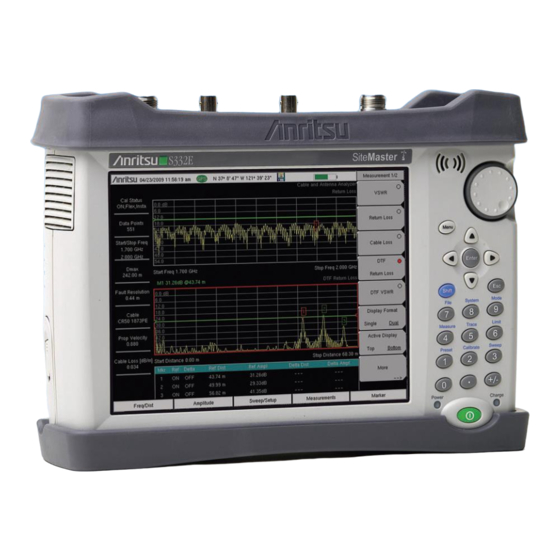
Site Master
Cable and Antenna Analyzer with
Spectrum Analyzer
S331E, 2 MHz to 4 GHz
S332E, 2 MHz to 4 GHz, Spectrum Analyzer, 9 kHz to 4 GHz
S361E, 2 MHz to 6 GHz
S362E, 2 MHz to 6 GHz, Spectrum Analyzer, 9 kHz to 6 GHz
Anritsu Company
Part Number: 10580-00253
490 Jarvis Drive
Revision: J
Morgan Hill, CA 95037-2809
Published: May 2016
USA
Copyright 2010, 2016 Anritsu Company
Advertisement
Table of Contents

Related Manuals for Anritsu S331E


Summary of Contents for Anritsu S331E
- Page 1 Site Master Cable and Antenna Analyzer with Spectrum Analyzer S331E, 2 MHz to 4 GHz S332E, 2 MHz to 4 GHz, Spectrum Analyzer, 9 kHz to 4 GHz S361E, 2 MHz to 6 GHz S362E, 2 MHz to 6 GHz, Spectrum Analyzer, 9 kHz to 6 GHz...
- Page 3 Site Master is a trademark of Anritsu Company. NOTICE Anritsu Company has prepared this manual for use by Anritsu Company personnel and customers as a guide for the proper installation, operation and maintenance of Anritsu Company equipment and computer programs. The drawings, specifications, and information contained herein are the property of Anritsu Company, and any unauthorized use or disclosure of these drawings, specifications, and information is prohibited;...
-
Page 7: Safety Symbols
Some or all of the following five symbols may or may not be used on all Anritsu equipment. In addition, there may be other labels attached to products that are not shown in the diagrams in this manual. - Page 8 For Safety Warning Always refer to the operation manual when working near locations at which the alert mark, shown on the left, is attached. If the operation, etc., is performed without heeding the advice in the operation manual, there is a risk of personal injury.
- Page 9 These hazardous compounds present a risk of injury or loss due to exposure. Anritsu Company recommends removing the battery for long-term storage of the instrument and storing the battery in a leak-proof, plastic container. Follow the environmental storage requirements specified in the product data sheet.
- Page 10 Safety-4 PN: 10580-00253 Rev. J S3xxE MM...
-
Page 11: Table Of Contents
Anritsu Customer Service Centers ........ - Page 12 Table of Contents (Continued) Chapter 6—Assembly Replacement Opening the Site Master Case ..........6-1 PCB Assembly Removal.
-
Page 13: Chapter 1-General Information
Appendix A and use them to record measured values. These test records form a record of the performance of the instrument. Anritsu recommends that you make a copy of the blank test records to document the measurements each time a Performance Verification is performed. -
Page 14: Recommended Test Equipment
1-3 Recommended Test Equipment General Information Recommended Test Equipment The following test equipment is recommended for use in testing and maintaining Anritsu Site Master Model S3xxE. Table 1-1 is a list of test equipment that is required for verifying the Spectrum Analyzer functions. - Page 15 Anritsu Model 15NN50-1.5C N(m) to N(m), 50 ohm Coaxial Cable BNC(m) to BNC(m), 50 ohm Any (Qty 2) Anritsu Model 2000-1627-R Synthesized Signal Source Frequency: 0.1 Hz to 20 GHz Anritsu Model MG3692A or B with Power Output to +13 dBm Options 2A, 4, 22, 15 Power Range: −70 to +20 dBm...
-
Page 16: Replaceable Parts
1128247, 1129004, and s/n < 1226201, plus some additional units per Service Note S3xxE-035 ND75282 S331E MB/VNA PCB Assembly with Locking connector (units without Option 21) 1233006 < s/n < 1608000, and some additional units per Service Note S3xxE-035 ND82168 S331E MB/VNA PCB Assembly(units without Option 21) s/n >... - Page 17 LCD Display, used with Inverter PCB (all unit s/n < 1329107, and some units with s/n < 1334000) 3-15-165 LCD Display for S331E unit serial number range: 1334000 < s/n < 1608000, All other S3xxE unit serial number range 1334000 < s/n < 1606000 3-15-174 LCD Display for S331E unit s/n >...
- Page 18 Table 1-4. List of Replaceable Parts Part Number Description 3-71625-1 Cable, LCD to Keypad, units with LCD Display 3-15-165 3-70675-1 Cable, LCD to Keypad, units with LCD Display 3-15-174 3-72621-4 Cable, LCD to Main PCB, units with LCD Display 3-15-147 and 3-15-165 3-70674-4 Cable, LCD to Main PCB, units with LCD Display 3-15-174 3-803-110...
-
Page 19: Chapter 2-Spectrum Analyzer Verification
Do not connect the external 10 MHz Reference to the Site Master. 2. Turn on the 10 MHz Reference Standard and the Anritsu MG3692X Synthesized Signal Source. 3. Set the MG3692X output to 1 GHz CW, with an RF Output Level of –30 dBm. - Page 20 (± 1.5 ppm) for the S362E only, and record in Table A-1. If the instrument fails the Section 2-1 “Frequency Accuracy Verification and Adjustment” test, then Note contact your local Anritsu Service Center (http://www.anritsu.com/Contact.asp). PN: 10580-00253 Rev. J S3xxE MM...
-
Page 21: Single Side Band (Ssb) Phase Noise Verification
1. Connect the 10 MHz reference source to the Anritsu MG3692X Synthesized Signal Source. 2. Turn on the 10 MHz reference source and the Anritsu MG3692X Synthesized Signal Source. 3. Set the MG3692X output to 1.00 GHz CW, with an RF output level of +0 dBm. -
Page 22: Spurious Response (Second Harmonic Distortion) Verification
1. Connect the 10 MHz reference source to the Anritsu MG3692X Synthesized Signal Source. 2. Turn on the 10 MHz reference source and the Anritsu MG3692X Synthesized Signal Source. 3. Set the MG3692X output to 50.1 MHz CW, with an RF Output Level of –30 dBm. - Page 23 Spectrum Analyzer Verification 2-3 Spurious Response (Second Harmonic Distortion) Verification 25. Press the Freq soft key and press the Center Freq soft key. 26. Use the keypad to enter 100.2 and press the MHz soft key. 27. Press the Shift key and then press the Trace (5) key, then press the Trace A Operations soft key. 28.
-
Page 24: Resolution Bandwidth Accuracy Verification
• BNC male to BNC male Coaxial Cable Procedure 1. Connect the 10 MHz reference source to the Anritsu MG3692X Synthesized Signal Source and the S332E or S362E Site Master. 2. Turn on the MG3692X, set the frequency to 1 GHz CW and Level to –30 dBm. -
Page 25: Spectrum Analyzer Absolute Amplitude Accuracy Verification
Equipment Required • Anritsu MG3692X Synthesized Signal Source • Anritsu ML2438A Dual Channel Power Meter • Anritsu MA2442D High Accuracy Power Sensors (2) • Anritsu 34NN50A 50 ohm Adapter • Anritsu 34RKNF50 50 ohm Adapter • Anritsu 15NN50-1.5C RF Coaxial Cable •... - Page 26 2-5 Spectrum Analyzer Absolute Amplitude Accuracy Verification Spectrum Analyzer Verification Test Setup Components Characterization 1. Turn on the ML2438A Power Meter, the MG3692X Signal Source, and the S332E or S362E Site Master. 2. On the power meter, press the Channel soft key, the Setup soft key and then the Channel soft key to display Channel 2 Setup menu.
- Page 27 Spectrum Analyzer Verification 2-5 Spectrum Analyzer Absolute Amplitude Accuracy Verification Measuring the Unit for 50 MHz Amplitude Accuracy 1. Remove Sensor A, add the adapter and connect it to the Spectrum Analyzer RF In connector of the S332E or S362E Site Master as shown in Figure 2-2.
-
Page 28: Amplitude Accuracy Across Frequency Verification
Equipment Required • Anritsu MG3692X Synthesized Signal Source • Anritsu ML2438A Dual Channel Power Meter • Anritsu MA2442D High Accuracy Power Sensors (2) • Anritsu 34NN50A 50 ohm Adapter • Anritsu 34RKNF50 50 ohm Adapter • Anritsu 15NN50-1.5C RF Coaxial Cable •... - Page 29 Spectrum Analyzer Verification 2-5 Spectrum Analyzer Absolute Amplitude Accuracy Verification Test Setup Component Characterization 1. Connect both MA2442D power sensors to the power meter and calibrate the sensors. 2. Connect the equipment as shown in Figure 2-3. 10 MHz Reference Adapter MG3692x Synthesized Signal Generator 10 dB Fixed...
- Page 30 2-5 Spectrum Analyzer Absolute Amplitude Accuracy Verification Spectrum Analyzer Verification Setup ML2438A Power Meter 10 MHz Reference MA2442D Adapter Sensor B 1870A Power Splitter MG3692x Synthesized Signal Generator 10 dB Attenuator N(m) to N(m) Adaptor SiteMaster Enter Back Shift Mode System File Limit...
- Page 31 Spectrum Analyzer Verification 2-5 Spectrum Analyzer Absolute Amplitude Accuracy Verification 9. Set the power meter to display Channel B. Press the Sensor key, the Cal Factor soft key, and then the Freq soft key. Use the keypad to enter the value matching the frequency of MG3692x as the input signal frequency, which sets the power meter to the proper power sensor cal factor.
-
Page 32: Residual Spurious Response Verification
2-15. Residual Spurious Response Test with Preamp Off Equipment Required • Anritsu 28N50-2 50 ohm Termination Procedure 1. Connect the 50 ohm Termination to the S332E or S362E Spectrum Analyzer RF In connector. 2. Press the On/Off key to turn on the S332E or S362E Site Master. -
Page 33: Residual Spurious Response Test With Preamp On
2-6 Residual Spurious Response Verification Residual Spurious Response Test with Preamp On Equipment Required • Anritsu 28N50-2 50 ohm Termination Procedure 1. Connect the 50 ohm Termination to the S332E or S362E Spectrum Analyzer RF In connector. 2. Press the On/Off key to turn on the S332E or S362E Site Master. -
Page 34: Displayed Average Noise Level (Danl)
S332E and S362E Site Master. This test is performed using the RMS detection mode. Equipment Required • Anritsu 28N50-2 50 ohm Termination Procedure 1. Connect the 50 ohm Termination to the S332E or S362E Spectrum Analyzer RF In connector. - Page 35 Spectrum Analyzer Verification 2-7 Displayed Average Noise Level (DANL) For example, if the marker shows a value of –100 dBm at 100 kHz RBW, the calculated value at 10 Hz RBW is –140 dBm. 23. Enter the calculated values in the test records. Use the Calculated for 10 Hz RBW column of Table A-11.
-
Page 36: Third Order Intercept (Toi) Verification
The following test verifies the Third Order Intercept point (also known as TOI or IP3) of the Spectrum Analyzer in the S332E and S362. Equipment Required • Anritsu MG3692x Synthesizer (Qty 2) • Anritsu ML2438A Power Meter • Anritsu MA2442D Power Sensor •... - Page 37 Spectrum Analyzer Verification 2-8 Third Order Intercept (TOI) Verification 19. Choose the larger of the two values from Step 16 Step 18, and put this value into the following equation as the “max” variable. TOI = –20 + [(–20 – max) / 2] dBm 20.
- Page 38 2-8 Third Order Intercept (TOI) Verification Spectrum Analyzer Verification 2-20 PN: 10580-00253 Rev. J S3xxE MM...
-
Page 39: Chapter 3-Cable And Antenna Analyzer Verification
Equipment Required • Frequency Counter Frequency: 2 GHz Anritsu Model MF2412B • RF Coaxial Cable Freq: DC to 18 GHz, N(m) to N(m), 50 ohm, Anritsu Model 15NN50-1.5C Procedure 1. Verify that the S3xxE is in Cable and Antenna Analyzer mode and preset the unit. -
Page 40: Return Loss Accuracy Verification
Equipment Required • Open/Short Frequency: DC to 18 GHz Anritsu Model 22N50 • Termination Frequency: DC to 18 GHz, Return Loss: 40 dB min. Anritsu Model 28N50-2 • 6 dB Offset Termination Frequency: DC to 6.0 GHz Anritsu Model SC7424 •... -
Page 41: Chapter 4-Option Verification
1. Press the Bias Tee Voltage soft key and change voltage from 15 V to 12 V, and then confirm that the Current soft key is set to Low. 2. Connect the Anritsu T3377 105 ohm load to the RF In test port. 3. Press the Bias Tee On/Off soft key to turn the Bias Tee On. -
Page 42: High Current Test Verification
A-16. Verify the voltage and current readings are within the specifications. 5. Press the Bias Tee On/Off soft key to turn the Bias Tee Off. Disconnect the Anritsu T2904 40 ohm load and connect the Anritsu T3536 78 ohm load to the RF In port. -
Page 43: Fault Verification
5. Press the Bias Tee soft key and confirm that the Current soft key is set to Low. 6. Press the Bias Tee Voltage soft key and enter 32 V. 7. Connect the Anritsu T2904 40 ohm load to the RF In port. 8. Press the Bias Tee On/Off soft key to turn the Bias Tee On. -
Page 44: Option 21, Transmission Measurement, System Dynamic Range
• Termination Frequency: DC to 18 GHz Return Loss: 40 dB min. Anritsu Model 28N50-2 • Termination Frequency: DC to 18 GHz Return Loss: 40 dB min. Anritsu Model 28NF50-2 • RF Coaxial Cable Freq: DC to 18 GHz N(m) to N(m), 50 ohm Anritsu Model 15NN50-1.5C Procedure 1. -
Page 45: Option 29, Power Meter Level Accuracy
Equipment Required • Anritsu MG3692X Synthesized Signal Source • Anritsu ML2438A Dual Channel Power Meter • Anritsu MA2442D High Accuracy Power Sensors (2) • Anritsu 34NN50A 50 ohm Adapter • Anritsu 34RKNF50 50 ohm Adapter • Anritsu 15NN50-1.5C RF Coaxial Cable •... - Page 46 4-4 Option 29, Power Meter Level Accuracy Option Verification Procedure Component Characterization: 1. Connect both MA2442D power sensors to the power meter and calibrate the sensors. 2. Connect the model 1870A power splitter to the MG3692A/B output and sensor B to one of the power splitter outputs as shown on the previous page.
-
Page 47: Option 31, Gps Verification
1. Connect the GPS antenna to the GPS Antenna connector on the S332E or S362E. On the S332E or S362E, change the mode to Spectrum Analyzer and preset the unit. If a fixed GPS antenna is not available, the Anritsu 2000-1528-R GPS antenna can be used for this test. -
Page 48: Gps Antenna Bias Tee Verification
4-5 Option 31, GPS Verification Option Verification 7. Connect the external 10 MHz Reference to the Anritsu MG3692x Synthesized Signal Generator. Note Do not connect the external 10 MHz Reference to the S3xxE Site Master. 8. Connect the output of the synthesized Signal Generator to the Spectrum Analyzer RF In of the S332E or S362E. - Page 49 Option Verification 4-5 Option 31, GPS Verification 12. Press the GPS Info soft key. Record the GPS Antenna Current reading in the Measured Value column of Table A-21. Verify that it is within specification. S3xxE MM PN: 10580-00253 Rev. J...
- Page 50 4-5 Option 31, GPS Verification Option Verification 4-10 PN: 10580-00253 Rev. J S3xxE MM...
-
Page 51: Chapter 5-Battery Information
Chapter 5 — Battery Information General Information The following information relates to the care and handling of the Anritsu battery pack and Lithium-Ion batteries. • The battery supplied with the Site Master may need charging before use. Before using the Site Master, the internal battery may be charged either in the unit using the AC-DC Adapter (40-187-R) or the 12-Volt DC adapter (806-141-R), or separately in the optional Dual Battery Charger (2000-1374). -
Page 52: Battery Pack Removal And Replacement
5-2 Battery Pack Removal and Replacement Battery Information Battery Pack Removal and Replacement This section provides instructions for the removal and replacement of the Site Master battery pack. Many of the procedures in this section are generic, and apply to many similar instruments. Photos Note and illustrations used are representative and may show instruments other than the Site Master. - Page 53 Battery Information 5-2 Battery Pack Removal and Replacement 4. With the battery access door completely removed, grasp the battery lanyard and pull the battery straight out of the unit, as illustrated in Figure 5-3. Figure 5-3. Removing the Battery 5. Replacement is the opposite of removal. Note the orientation of the battery contacts, and be sure to insert the battery with the contacts facing the front of the unit, refer to Figure 5-3 Figure...
- Page 54 5-2 Battery Pack Removal and Replacement Battery Information PN: 10580-00253 Rev. J S3xxE MM...
-
Page 55: Chapter 6-Assembly Replacement
Chapter 6 — Assembly Replacement Opening the Site Master Case Many of the procedures in this section are generic, and apply to many similar instruments. Photos Note and illustrations used are representative and may not match your instrument. Only qualified personnel should open the case and replace internal assemblies. Assemblies shown Table 1-4 are typically the only items that may be replaced. - Page 56 6-1 Opening the Site Master Case Assembly Replacement 4. Use a Phillips screwdriver to remove the six screws securing the two halves of the Site Master case together (Figure 6-2). Carefully lift this side first Location of the 6 screws to remove. Figure 6-2.
-
Page 57: Pcb Assembly Removal
Assembly Replacement 6-2 PCB Assembly Removal PCB Assembly Removal Procedures in this section are generic, and apply to many similar instruments. Photos and Note illustrations of assemblies are representative, actual assemblies may vary. This procedure provides instructions to remove the Motherboard/VNA and SPA (if installed) from the Site Master case. -
Page 58: Spa Assembly Replacement
6-3 SPA Assembly Replacement Assembly Replacement SPA Assembly Replacement This procedure provides instructions to remove the SPA assembly. 1. Open the case as described in Section 6-1 “Opening the Site Master Case”. 2. Remove the PCB assembly from the front panel as described in Section 6-2 “PCB Assembly Removal”. -
Page 59: Spa And Mb/Vna N Connector Replacement
Assembly Replacement 6-4 SPA and MB/VNA N Connector Replacement SPA and MB/VNA N Connector Replacement This procedure provides instructions to replace the N connector attached to the SPA (if installed) or MB/VNA assembly. 1. Open the case as described in Section 6-1 “Opening the Site Master Case”. -
Page 60: Gps (Opt. 31) Replacement
6-5 GPS (Opt. 31) Replacement Assembly Replacement GPS (Opt. 31) Replacement This procedure provides instructions to replace the GPS assembly. 1. Open the case as described in Section 6-1 “Opening the Site Master Case”. 2. Remove the PCB assembly from the front panel as described in Section 6-2 “PCB Assembly Removal”. -
Page 61: Option Assembly Replacement
Assembly Replacement 6-6 Option Assembly Replacement Option Assembly Replacement This procedure provides instructions to replace the Ethernet (Option 411) or CPRI (Option 751) assembly. 1. Open the case as described in Section 6-1 “Opening the Site Master Case”. 2. Remove the PCB assembly from the front panel as described in Section 6-2 “PCB Assembly Removal”. -
Page 62: Fan Assembly Replacement
6-8 Fan Assembly Replacement Assembly Replacement Fan Assembly Replacement This procedure provides instructions to replace the fan assembly. 1. Open the case as described in Section 6-1 “Opening the Site Master Case”. 2. Remove the PCB assembly from the front panel as described in Section 6-2 “PCB Assembly Removal”. -
Page 63: Lcd Assembly Replacement
Assembly Replacement 6-9 LCD Assembly Replacement LCD Assembly Replacement This procedure provides instructions to replace the liquid crystal display (LCD). 1. Open the case as described in Section 6-1 “Opening the Site Master Case”. 2. Remove the PCB assembly as described in Section 6-2 “PCB Assembly Removal”. - Page 64 6-9 LCD Assembly Replacement Assembly Replacement 4. Turn the LCD assembly over and disconnect the front half of the case from the LCD assembly (Figure 6-12). Disconnect Cable Figure 6-12. Replacing the LCD Assembly 5. Use a Phillips screwdriver to remove the four screws securing the LCD to the housing, see Figure 6-13.
-
Page 65: 6-10 Lcd Backlight Pcb Removal And Replacement
Assembly Replacement 6-10 LCD Backlight PCB Removal and Replacement 6. Disconnect the LCD backlight cable from the LCD backlight PCB. 7. Disconnect the LCD cable from the side of the LCD. 8. Carefully remove the LCD. 9. Reverse the above steps to install the replacement LCD. Pay attention to the routing of the LCD Backlight Cable. -
Page 66: Keypad And Keypad Pcb Replacement
If no touch screen calibration data is stored in the new keypad PCB when powering on a unit, it will stay at the boot up screen with the Anritsu logo shown and a message at the bottom of the screen stating: Failed to load touch screen calibration data. -
Page 67: 6-12 Touch Screen Replacement
Assembly Replacement 6-12 Touch Screen Replacement 6-12 Touch Screen Replacement This procedure provides instructions to replace the touch screen. 1. Open the case as described in Section 6-1 “Opening the Site Master Case”. 2. Remove the PCB assembly from the front panel as described in Section 6-2 “PCB Assembly Removal”. - Page 68 6-12 Touch Screen Replacement Assembly Replacement 6-14 PN: 10580-00253 Rev. J S3xxE MM...
-
Page 69: Chapter 7-Troubleshooting
(Anritsu part number 40-187-R) to the unit allowing the battery to charge. 2. Battery may be the wrong type. Use only Anritsu approved battery packs. Some non-approved battery packs will fit into the MP1026B, but are electrically incompatible and will not charge correctly. -
Page 70: Other Problems
7-3 Other Problems Troubleshooting Other Problems Touch Screen Problems: Unit boots correctly, but the touch screen is unresponsive. 1. The touch screen may have lost its calibration data. Press Shift then 0 to enter the touch screen calibration procedure. Follow the on-screen directions. 2. -
Page 71: Appendix A-Test Records
Appendix A — Test Records This appendix provides test records that can be used to record the performance of the S3xxE. Anritsu recommends that you make a copy of the following test record pages and document the measurements each time a Performance Verification is performed. Continuing to document this process each time provides a detailed history of the instrument’s performance, allowing for trends to be observed. -
Page 72: Test Records For Spectrum Analyzer Verification
A-1 Test Records for Spectrum Analyzer Verification S3____E Firmware Rev: ______________ Operator: ____________________ Date: _____________ Serial Number: _______________ Options: ___________________________________________________ Test Records for Spectrum Analyzer Verification Table A-1. Spectrum Analyzer Frequency Accuracy Frequency Measured Value Deviation Specification 1 GHz ± 1.5 kHz (± 1.5 ppm) 3.9 GHz ±... - Page 73 A-1 Test Records for Spectrum Analyzer Verification S3____E Firmware Rev: ______________ Operator: _________________ Date: _____________ Serial Number: _______________ Options: ___________________________________________________ Table A-4. Spectrum Analyzer Resolution Bandwidth Accuracy BW Setting Span Lower Limit Measured Values Upper Limit 3 MHz 4.5 MHz Auto 2.7 MHz 3.3 MHz...
- Page 74 A-1 Test Records for Spectrum Analyzer Verification S3____E Firmware Rev: ______________ Operator: _________________ Date: _____________ Serial Number: _______________ Options: ___________________________________________________ Table A-6. Spectrum Analyzer 50 MHz Absolute Amplitude Accuracy Input Power Level Reference Level Input Atten. Level Measured Reading Specification 0 dBm 10 dBm 30 dB...
- Page 75 A-1 Test Records for Spectrum Analyzer Verification Table A-7. Spectrum Analyzer Absolute Amplitude Accuracy Across Frequency Setup Table Required Sensor B Required Sensor B Required Sensor B reading for –2 dBm @ reading for –30 dBm @ reading for –50 dBm @ Frequency Attenuator output Attenuator output...
- Page 76 A-1 Test Records for Spectrum Analyzer Verification S3____E Firmware Rev: ______________ Operator: _________________ Date: _____________ Serial Number: _______________ Options: ___________________________________________________ S3____E Firmware Rev: ______________ Operator: _________________ Date: _____________ Serial Number: _______________ Options: ___________________________________________________ Table A-8. Spectrum Analyzer Absolute Amplitude Accuracy Across Frequency (1 of 4) Reference Freq Input Power...
- Page 77 A-1 Test Records for Spectrum Analyzer Verification Table A-8. Spectrum Analyzer Absolute Amplitude Accuracy Across Frequency (2 of 4) Reference Freq Input Power Level Setting Atten. Level Marker 1 Reading Spec (MHZ) (dBm) (dBm) Setting (dB) Pre-Amp Setting (dBm) (dB) –50 –40 ±1.25...
- Page 78 A-1 Test Records for Spectrum Analyzer Verification Table A-8. Spectrum Analyzer Absolute Amplitude Accuracy Across Frequency (3 of 4) Reference Freq Input Power Level Setting Atten. Level Marker 1 Reading Spec (MHZ) (dBm) (dBm) Setting (dB) Pre-Amp Setting (dBm) (dB) –50 –40 2000...
- Page 79 A-1 Test Records for Spectrum Analyzer Verification Table A-8. Spectrum Analyzer Absolute Amplitude Accuracy Across Frequency (4 of 4) Reference Freq Input Power Level Setting Atten. Level Marker 1 Reading Spec (MHZ) (dBm) (dBm) Setting (dB) Pre-Amp Setting (dBm) (dB) –50 –40 5000...
- Page 80 A-1 Test Records for Spectrum Analyzer Verification S3____E Firmware Rev: ______________ Operator: _________________ Date: _____________ Serial Number: _______________ Options: ___________________________________________________ Table A-9. Spectrum Analyzer Residual Spurious with Preamp Off Start Freq. Stop Freq. Measured Values Specification ≤ –90 dBm 10 MHz 50 MHz 1 kHz 300 Hz...
- Page 81 A-1 Test Records for Spectrum Analyzer Verification S3____E Firmware Rev: ______________ Operator: _________________ Date: _____________ Serial Number: _______________ Options: ___________________________________________________ Table A-11. Spectrum Analyzer DANL with Pre Amp Off Measured Value at Calculated for Start Freq Stop Freq 100 kHz RBW 10 Hz RBW Specification 10 MHz...
-
Page 82: Test Records For Cable And Antenna Analyzer Verification
A-2 Test Records for Cable and Antenna Analyzer Verification S3____E Firmware Rev: ______________ Operator: _________________ Date: _____________ Serial Number: _______________ Options: ___________________________________________________ Test Records for Cable and Antenna Analyzer Verification Table A-14. VNA Frequency Accuracy Frequency Measured Value Specification 2 GHz (2000 MHz) ±... -
Page 83: Test Records For Options Verification
A-3 Test Records for Options Verification S3____E Firmware Rev: ______________ Operator: _________________ Date: _____________ Serial Number: _______________ Options: ___________________________________________________ Test Records for Options Verification Table A-16. Option 10, Bias Tee Voltage Voltage Current Setting Measured Values Specification Specification 105 ohm Load, Low Current 12 V 12 ±... - Page 84 A-3 Test Records for Options Verification S3____E Firmware Rev: ______________ Operator: _________________ Date: _____________ Serial Number: _______________ Options: ___________________________________________________ Table A-18. Option 29, Characterization Chart for Power Meter Verification Test Power Level @ 50 MHz Required Sensor B Reading 0 dBm –50 dBm Test Power Level @ 3900 MHz (S332E only)
- Page 85 A-3 Test Records for Options Verification Table A-21. Option 31, GPS Receiver Bias Tee Verification Voltage Setting Measured Value Specification 3.3 V 32 mA ± 15 % (27.2 mA to 36.8 mA) 5.0 V 55.6 mA ± 15 % (47.3 mA to 63.9 mA) S3xxE MM PN: 10580-00253 Rev.
- Page 86 A-3 Test Records for Options Verification A-16 PN: 10580-00253 Rev. J S3xxE MM...
- Page 88 Anritsu Company 490 Jarvis Drive Anritsu utilizes recycled paper and environmentally conscious inks and toner. Morgan Hill, CA 95037-2809 http://www.anritsu.com...
Need help?
Do you have a question about the S331E and is the answer not in the manual?
Questions and answers