SciCan HYDRIM C61w G4 Service Manual
Instrument washer
Hide thumbs
Also See for HYDRIM C61w G4:
- Operator's manual (81 pages) ,
- Quick reference manual (2 pages) ,
- Preventative maintenance (3 pages)
Table of Contents
Advertisement
Quick Links
Advertisement
Table of Contents
Troubleshooting

Related Manuals for SciCan HYDRIM C61w G4


Summary of Contents for SciCan HYDRIM C61w G4
- Page 1 HYDRIM C61w G4 INSTRUMENT WASHER • Service Manual • Manuel de l’utilisateur...
-
Page 2: Table Of Contents
Contents 1. Introduction ........4 4. Removing and Replacing Panels ... 35 1.1 Overview ..........4 4.1 Removing and reinstalling the top panel .. 36 1.2 Unit at a glance ........5 4.2 Removing and reinstalling the left panel .. 36 With cover and panels removed top .. - Page 3 Flow Diagram .......... 79 EU Representative HYDRIM and STATIM are registered trademarks of SciCan Ltd. BRAVO, HIP, and SysTM are trademarks of SciCan Ltd. All other trademarks referred to SciCan GmbH in this manual are the property of their respective owners.
-
Page 4: Introduction
1.1 Overview This guide provides instructions for the servicing and repair of the HYDRIM C61w G4 ® Instrument Washer. Every attempt has been made to provide accurate, detailed instructions. HYDRIM C61w G4 instrument washer cycle description chart Cycle Prewash Wash Rinse P0 –... -
Page 5: Unit At A Glance
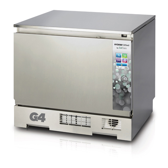
1 Introduction Figure 1 1.2 HYDRIM Unit at a glance With cover and panels in place Power switch Dryer outlet Ethernet port Kickplate Water softener RS232 port HEPA filter Cold water inlet Wash arms (top not shown) Dryer exhaust Coarse filter Hot water inlet Door latch Fuses... -
Page 8: Specifications
1 Introduction 1.3 Specifications Machine dimensions: Length: 52 cm 20.5" Width: 59.8 cm 23.5" Depth: 52.6 cm 20.7" Depth with door open: 82.9 cm 32.6" Weight : 44 kg 97 lbs Running noise: 65 dB Hot and cold water connections G 3/4"... -
Page 9: Safety Information
SciCan shall not be liable for incidental, special or consequential damages caused by any maintenance or services performed on the HYDRIM C61w G4 by a third party or for the use of equipment or parts manufactured by a third party, including lost profits, any commercial loss, economic loss, or loss arising from personal injury. -
Page 10: Tools And Hardware
Reporting • It is vital for SciCan to learn of any problem in the field. This information will help SciCan solve the problem quickly and improve product reliability in new units. Biological waste •... -
Page 11: Shipping Instructions
The HYDRIM C61w G4 must be properly grounded. • The HYDRIM C61w G4 is equipped with an air gap / anti-suction device to prevent backflow of dirty water into the water supply. No other air gap device is necessary. Detailed installation instructions are available in a separate document. Installation should only be undertaken by a manufacturer approved technician. -
Page 12: Setting Water Softener
1 Introduction 1.8 Setting the water softener Water hardness and salt regeneration levels The HYDRIM C61w G4 is equipped with a built-in water softening system that must be adjusted according to the local water hardness. To read local water hardness, proceed as follows: 1. -
Page 13: Setting The Language
1 Introduction IMPORTANT: The HYDRIM’s water softening system reduces the water hardness by taking out Calcium Carbonate. If the water testing results show that the water hardness is outside the unit's range of adjustment, or if other dissolved solids in the water cause stains or deposits on the instruments or chamber, an external water treatment system may be required. -
Page 14: Setting The Date
1 Introduction NOTE: If the HYDRIM is connected to a network, it is important to also enter the correct Time Zone. Enter the Time submenu, select Time Zone and scroll and select your local time zone. To change your unit to display 12-hour time format (24-hour time format is the default setting), go to the Setup menu and use to scroll to TIME 12/24, select it and toggle to 12. -
Page 15: Adjusting The Screensaver Delay
1 Introduction 1.15 Adjusting the screensaver delay To change the length of time before the screensaver is activated, follow these steps: Screensaver Scroll to and select. to scroll through your time options. When you have found the amount of time you require, press it. Press to save and return to the Setup menu. -
Page 16: Adjusting The Salt Regeneration
1 Introduction 1.19 Adjusting the salt regeneration Salt regeneration should be set according to the local water hardness. See section 1.8 Setting the water softener for instructions on determining correct settings. To set salt regeneration, follow these steps: Set Regeneration Scroll to and select. -
Page 17: Creating A User Name
1 Introduction 1.22 Creating a User Name Up to four unique User Names can be created. To assign a User Name follow these steps: User Scroll to and select. To assign a user name, select User Name and use the alphabetic keypad to enter a name (up to 12 characters) and press to save. -
Page 18: Setting Up Process Enforced Usage
1.25 Connecting to a network The HYDRIM C61w G4 has a 10/100Base-T Ethernet port located at the back of the unit. To connect your HYDRIM to a network using a router, follow these steps: 1. Connect your network cable to the Ethernet port at the back of the unit. If your office uses a router, the router should automatically assign the unit an IP address. -
Page 19: Connecting To A Wireless Network
1.26 Connecting to a wireless network The HYDRIM can be configured for wireless use by connecting the Ethernet port to an external wireless bridge / access point. SciCan currently recommends the use of the ® ®... -
Page 20: Routine Procedures And Maintenance
2 Routine Procedures and Maintenance 2.1 Replacing the HIP™ Ultra cleaning solution To replace the cleaning solution, follow these steps: 7 1 2 ULTRA Remove the empty cleaning Turn the power OFF, h Instrument Protection Disconnect the cleaning www.scica open the door and pull out solution bag and discard solution connector. -
Page 21: Changing The Hepa Filter
2 Routine Procedures and Maintenance 2.2 Changing the HEPA filter When the message “Replace air filter” appears, the HEPA filter is in need of changing. To change the filter, proceed as follows: 1. Open the kickplate below the front door of the unit and turn the power off. -
Page 22: Cleaning The Chamber
Figure 7 2.4 Cleaning the chamber The HYDRIM C61w G4 chamber can be cleaned using the “Cleaning” program in the User menu. This cycle is used to periodically remove hardwater deposits from the chamber walls and racks. Pour 0.5 litres of vinegar into the chamber before starting the cycle. From the User menu, select “Cleaning”... -
Page 23: Using The Hydrim Remote Access Function
From the TOOLS page, click on the LOCAL CONTROL tab. Log in using the following credentials: Username: scican Password: s23can173 Click on the start button to start a local connection. It will open up a page that mirrors the HYDRIM unit’s touchscreen so that it can be controlled remotely within a local network. -
Page 24: Annual Service Requirements
Use your mouse to click and select touchscreen elements. 2.8 Annual Service Requirements The HYDRIM C61w G4 is designed to be maintenance free; however, it is recommended that a SciCan-approved service technician perform an annual check. The following checks are recommended in order to maintain optimum performance of the unit. - Page 25 2 Routine Procedures and Maintenance • Inspect and clean sump filters (check sump for debris) • Check wash arms for blockages and remove them for cleaning if required. • Review error history • Software upgrade (if necessary) • Check individual component functionality. Go to the technician menu (enter access code 7919) and select ‘Diagnostic Tools’...
-
Page 26: Diagnostics And Troubleshooting
3 Diagnostics and Troubleshooting 3.1 Using the service menu To access the service menu, select the image of the technician and enter the service code 7919 on the keypad. User Technician Setup Cycle Settings SW Upgrade Wash Test Set Regeneration Network Setup Chemical Setup Diagnostic Tools... -
Page 27: Using The Setup Menu
3 Diagnostics and Troubleshooting 3.2 Using the setup menu To access functions and settings on the setup menu, proceed as follows: User Technician Setup Language Selection Set Printer Prepare for Shipping Country Baud Rate Date/Time Set EOL CR/LF Unit No. Set Regeneration Network Setup LCD Contrast... -
Page 28: Using The User Menu
3 Diagnostics and Troubleshooting 3.3 Using the user menu To access functions and settings on the user menu, proceed as follows: User Technician Setup Cleaning Set Drying Time Set Wash Time Cycle Count Process Enforced User... -
Page 29: Using Software Tools For Diagnostics
3 Diagnostics and Troubleshooting 3.4 Using software tools for diagnostics 3.4 Using software tools for diagnostics Within the service menu, there are two useful tools for troubleshooting: Debug screen Within the service menu, there are two useful tools for troubleshooting: Debug screen and and IO status screen. -
Page 30: I/O Status Screen
3 Diagnostics and Troubleshooting I/O status screen The IO status screen is used when testing components and wires for functionality without the cycle running. -
Page 31: Troubleshooting Cycle Faults
3 Diagnostics and Troubleshooting 3.5 Troubleshooting cycle faults Cycle Fault Effect Problem Possible Causes CF 1 Water Heating Improper wash, cycle Chamber temperature This is caused by a water aborted less than a set point heater malfunction: Failure after a timeout, •... - Page 32 3 Diagnostics and Troubleshooting Cycle Fault Effect Problem Possible Causes CF 8 Cycle Fault Drying aborted Air temperature less This is caused by a heater malfunction: than a set point after a timeout • Check air heater wire harness for loose contacts.
- Page 33 3 Diagnostics and Troubleshooting Cycle Fault Effect Problem Possible Causes CF 16 Ambient Cycle interrupted Operating temperature The room or enclosure is too for one or both logic warm and not allowing the Temperature Error boards is too high unit to adequately cool: Check that fans are working.
- Page 34 3 Diagnostics and Troubleshooting Cycle Fault Effect Problem Possible Causes CF 25 Vref Error Cycle cannot start or Vref and VCC drift, post The power supply 5V output cycle interrupted CF 25 if VCC and Vref voltage is fluctuating: are more than 3% apart •...
-
Page 35: Removing And Replacing Panels
PRECAUTIONS If you have questions about the unit you are repairing, please do not hesitate to contact your local SciCan representative for information. Also, the HYDR IM is heavy. Exercise caution and seek assistance when lifting or carrying units. EXERCISE CAUTION • Hazardous voltages are accessible when the cover is removed. -
Page 36: Removing And Reinstalling The Top Panel
4. Removing and Replacing Panels 4.1 Removing and reinstalling the top panel 1. Open door to remove 3 screws under the top cover’s front edge. (Figure 9) 2. Pull top cover to the front and tip up to remove. To reinstall, place the cover on top of unit and slightly forward. Push it to the back to engage the tabs. -
Page 37: Removing And Reinstalling The Right Panel
4. Removing and Replacing Panels 4.3 Removing and reinstalling the right panel 1. Open the door to remove 3 screws in the front. (Figure 11) 2. Remove 3 screws at the back of the unit. (not shown) 3. There are 2 tabs at the bottom of the panel. To disengage these from the chassis, pull the panel out from the top and slide it down. -
Page 38: Removing And Reinstalling The Bottom Panel
4. Removing and Replacing Panels 4.5 Removing and reinstalling the bottom panel 1. With the unit still hooked up, start by disconnecting the cap from the chemical detergent pouch and then running a shipping cycle from the set-up menu. This will drain most of the water and detergent from the unit. -
Page 39: Front Components
PRECAUTIONS If you have questions about the unit you are repairing, please do not hesitate to contact your local SciCan representative for information. Also, the HYDR IM is heavy. Exercise caution and seek assistance when lifting or carrying units. EXERCISE CAUTION • Hazardous voltages are accessible when the cover is removed. -
Page 40: Removing And Reinstalling The Kickplate
5. Front Components 5.1 Removing and reinstalling the kickplate CAUTION: cover sharp edges on the filter cutout with tape to protect hands. 1. Open kickplate and remove HEPA filter. (Figure 14a) 2. Detach the dryer inlet duct by pulling off the HEPA filter gasket and pulling the dryer inlet duct out of the groove so that you can push it free of the kickplate. -
Page 41: Removing And Reinstalling The Power Switch
5. Front Components 5.2 Removing and reinstalling the power switch 1. Remove top cover and left panel. 2. Remove two contacts from the back of the power switch using needle nose pliers. This will help to pull the power switch through the cut out in the chassis. -
Page 42: Door Components
PRECAUTIONS If you have questions about the unit you are repairing, please do not hesitate to contact your local SciCan representative for information. Also, the HYDR IM is heavy. Exercise caution and seek assistance when lifting or carrying units. EXERCISE CAUTION • Hazardous voltages are accessible when the cover is removed. -
Page 43: Removing And Reinstalling Door Fascia
6. Door Components 6.1 Removing and reinstalling the door fascia 1. Open door and remove 3 screws on right side of door, 2 on inside left and 2 on the inside top. (Figure 16a) 2. Slide the door fascia up just enough to disengage it. CAUTION: the LCD and controller are attached to the door fascia. -
Page 44: Removing And Reinstalling Door Springs
6. Door Components 6.2 Removing and reinstalling the door springs To remove the left side door spring: 1. Remove top cover 2. Remove left panel. 3. Unhook the door spring to replace. (Figure 17a) To reinstall, reverse procedure. Door spring kit – part # 01-113298S (kit has set of two springs and rope) spring Figure 17a... -
Page 45: Removing And Reinstalling The Door
6. Door Components 6.3 Removing and reinstalling the door 1. Remove door fascia. (See 6.1 Removing and reinstalling door fascia) 2. Unhook LCD bracket from service position. (Figure 18a) 3. Remove door rebar by removing the 2 screws at left and 3 screws at right. -
Page 46: Removing And Reinstalling Lcd And Lcd Controller
6. Door Components 6.4 Removing and reinstalling LCD and LCD controller 1. Remove the door fascia to access the LCD. (See 6.1 Removing and reinstalling door fascia) 2. Remove all wire connections from the controller board and cut cable ties affixing the wiring harness to the LCD. -
Page 47: Removing And Reinstalling The Door Latch Assembly
6. Door Components 6.7 Removing and reinstalling the door latch assembly 1. Remove the door fascia. (See 6.1 Removing and reinstalling door fascia) 2. Remove the 3 screws on the latch assembly (2 screws at inside top of door and 1 at right of assembly). -
Page 48: Removing And Replacing The Door Seal
6. Door Components 6.10 Removing and replacing the door seal 1. To remove the door seal, open the door, pull the old seal out and remove all silicone residues. (Figure 21a) Figure 21a To replace the door seal: 1. Use a silicone sealant to adhere the new door seal to the chamber. -
Page 49: Removing And Replacing The Chamber Seal
6. Door Components 6.11 Removing and replacing the chamber seal (Figure 22) 1. Before pulling the chamber seal, note how the bottom left and right edges touch the bottom of the chamber. 2. Pull the seal out from the seal recess. To replace: 1. -
Page 50: Right Side Components
PRECAUTIONS If you have questions about the unit you are repairing, please do not hesitate to contact your local SciCan representative for information. Also, the HYDR IM is heavy. Exercise caution and seek assistance when lifting or carrying units. EXERCISE CAUTION • Hazardous voltages are accessible when the cover is removed. -
Page 51: The Dc Power Source
7. Right Side Components DC power source reservoir filling pump pressure chemical switch bracket dosing/bellows pump Figure 23 I/O board dosing reservoir 7.1 Removing and reinstalling DC power source 1. Turn off unit and disconnect power cord. 2. Remove 7 wire contacts from the DC power source. -
Page 52: Removing And Reinstalling The Reservoir Filling Pump
7. Right Side Components 7.2 Removing and reinstalling the reservoir filling pump (Figure 25) 1. Disconnect chemical bag and run shipping cycle to drain dosing system. 2. Turn off unit and disconnect power cord. 3. Remove right panel. 4. Remove 2 wire connections at top of pump. 5. -
Page 53: Removing And Reinstalling The Dosing Reservoir
7. Right Side Components 7.4 Removing and reinstalling the dosing reservoir (See Figure 26a) 1. Disconnect chemical bag, run shipping cycle to drain system, power off unit, and disconnect power cord. 2. Remove right panel. 3. Cut cable ties and disconnect inlet and outlet tubing from reservoir bottom. 4. -
Page 54: Removing And Reinstalling The Chemical Bracket
7. Right Side Components 7.6 Removing and reinstalling the chemical bracket 1. Remove unit top panel. 2. Remove unit right panel. 3. Remove the chemical detergent drawer and bag. 4. Remove 1 screw at the back of the reservoir filling pump bracket. 5. -
Page 55: Removing And Reinstalling The Pressure Switch
7. Right Side Components 7.7 Removing and reinstalling the pressure switch 1. Remove top cover, right panel and back panel. Remove power supply fan. 3. Remove wiring from pressure switch. 4. Remove 2 screws connecting the rear upper cross-member of the chassis and the left upright to access the snap mount that fastens the pressure switch to the pressure switch bracket. -
Page 56: Left Side Components
PRECAUTIONS If you have questions about the unit you are repairing, please do not hesitate to contact your local SciCan representative for information. Also, the HYDR IM is heavy. Exercise caution and seek assistance when lifting or carrying units. EXERCISE CAUTION • Hazardous voltages are accessible when the cover is removed. -
Page 57: Removing And Reinstalling The Air Gap
8. Left Side Components dryer assembly door spring air gap dryer heater Figure 30 water softener dryer boot system 8.1 Removing and reinstalling the air gap 1. Run a shipping cycle to drain. 2. Remove the top panel, left panel and back panel. (See Section 4. Removing and Replacing Panels.) 3. - Page 58 8. Left Side Components 9. Disconnect the pump breather tube at the pump. (Figure 31b) 10. Disconnect the 2 hose clamps using pliers to slide them down and out of the way. (Figure 31c) 11. To remove the air gap, pull it up to clear the water softener connections.
-
Page 59: Removing And Reinstalling The Dryer Heater
8. Left Side Components door spring 8.2 Removing and reinstalling the dryer heater 1. Remove the left panel and cover. (See Section 4. Removing and Replacing Panels.) 2. Disconnect the heater wiring. 3. Unscrew the 2 screws. 4. Cut the wiring cable tie. 5. -
Page 60: Rear Components
PRECAUTIONS If you have questions about the unit you are repairing, please do not hesitate to contact your local SciCan representative for information. Also, the HYDR IM is heavy. Exercise caution and seek assistance when lifting or carrying units. EXERCISE CAUTION • Hazardous voltages are accessible when the cover is removed. -
Page 61: Removing And Replacing
9. Rear Components power source fan Figure 34 dryer exhaust duct air gap pump 9.1 Removing and reinstalling the power source fan (Figure 35) 1. Remove top cover and back cover. (See Section 4. Removing and Replacing Panels.) 2. Disconnect wires 91 and 92 from the snap connection on the top wiring harness. -
Page 62: Removing And Reinstalling The Air Gap Pump
9. Rear Components 9.2 Removing and reinstalling the air gap pump 1. Run a shipping cycle to drain the unit. 2. Remove the top cover, left panel and back cover. (See Section 4. Removing and Replacing Panels.) 3. Remove the spring clips on hoses at the bottom of the air gap. -
Page 63: Removing And Reinstalling The Exhaust Duct
9. Rear Components 9.3 Removing and reinstalling the exhaust duct 1. Power off unit and disconnect power cord. 2. Remove top cover and back panel. 3. From inside the chamber, remove the 2 screws to release the splash shield. (Figure 37a) 4. -
Page 64: Top Components
PRECAUTIONS If you have questions about the unit you are repairing, please do not hesitate to contact your local SciCan representative for information. Also, the HYDR IM is heavy. Exercise caution and seek assistance when lifting or carrying units. EXERCISE CAUTION • Hazardous voltages are accessible when the cover is removed. -
Page 65: Removing And Reinstalling The Usb Port
10. Top Components Figure 38 air gap test port upper wash upper wash DC power USB port overflow tray arm inlet arm sensor source 10.1 Removing and reinstalling the USB port (Figure 38) 1. Remove top cover, left and right panels. (See Section 4. Removing and Replacing Panels.) 2. -
Page 66: Disconnecting And Reconnecting The Upper Wash Arm Inlet
10. Top Components 10.2 Disconnecting and reinstalling the upper wash arm inlet (Figure 38) 1. Remove the top cover. (See Section 4.1 Removing and reinstalling the top cover.) 2. Pull down on the upper wash arm inside the chamber to remove it. 3. -
Page 67: Bottom Components
PRECAUTIONS If you have questions about the unit you are repairing, please do not hesitate to contact your local SciCan representative for information. Also, the HYDR IM is heavy. Exercise caution and seek assistance when lifting or carrying units. EXERCISE CAUTION • Hazardous voltages are accessible when the cover is removed. -
Page 68: Removing And Reinstalling The Recirculation Pump
11. Bottom Components sump w/water heater dryer motor dryer exhaust duct hose water softening system Figure 39 solenoids drain pump water temperature recirculation sensor pump 11.1 Removing and reinstalling the recirculation pump 1. Disconnect the detergent bag and remove bag and drawer. 2. -
Page 69: Removing And Reinstalling The Water Heater
11. Bottom Components To reinstall the recirculation pump: 1. Place pump into position. 2. Reattach wires in the following sequence. • red – 34/35 • Yellow/green – 43 • Brown – 18 3. Attach hoses and tighten hose clamps. 4. Reattach diagonal brace. 5. Reinstall bottom panel. To reinstall, slide the panel back into position, replace the screws and pull the rubber standoffs back through the panel. -
Page 70: Removing And Reinstalling The Drain Pump
11. Bottom Components 11.3 Removing and reinstalling the drain pump 1. Disconnect the detergent bag and remove bag and drawer. 2. Run a shipping cycle to drain the unit, disconnect power and flip unit onto its back. (For detailed instructions on flipping the unit, see Section 4.5 Removing and reinstalling the bottom panel.) 3. -
Page 71: Remove And Replace The Sump Temperature Sensor
11. Bottom Components 11.4 Removing and reinstalling the sump temperature sensor 1. Disconnect the detergent bag and remove bag and drawer. 2. Run a shipping cycle to drain the unit, disconnect power and flip unit onto its back. (For detailed instructions on flipping the unit see Section 4.5 Removing and reinstalling the bottom panel.) 3. -
Page 72: Removing And Reinstalling The Bottom Rpm Sensor
11. Bottom Components 11.5 Removing and reinstalling the bottom RPM sensor 1. Disconnect the detergent bag and remove bag and drawer. RPM sensor wires 2. Run a shipping cycle to drain the unit, disconnect power and flip unit onto its back. -
Page 73: Removing And Reinstalling The Dryer Motor
11. Bottom Components 11.6 Removing and reinstalling the dryer motor 1. Disconnect the detergent bag and remove bag and drawer. 2. Run a shipping cycle to drain the unit, disconnect power and flip unit onto its back. (For detailed instructions on flipping the unit, see chassis Section 4.5 Removing and... -
Page 74: Removing And Reinstalling The Water Softener System
11. Bottom Components 11.7 Removing and reinstalling the water softener system 1. Disconnect the detergent bag and remove bag and drawer. 2. Run a shipping cycle to drain the unit and disconnect power. 3. Remove the top and left panels. 4. -
Page 75: Removing And Reinstalling The Water Valves
11. Bottom Components 11.8 Removing and reinstalling the water valves Figure 47 A/C power contacts RO valve hot water valve cold water valve (not shown) 1. Valves for hot water, cold water and R/O water (if fitted) inlets can be accessed from the unit bottom. 2. -
Page 76: Spare Parts List
12. Spare Parts 01-113265S 2-Level Pressure Switch, C61 01-113253 3 Cassette/2 Basket Rack, C61 01-113252 4 Cassette Rack, C61 01-113251 6 Cassette Rack, C61 01-113318S Backflow Preventer, C61 01-113547 Basket w/ Hinged Lid, C61 01-113285S Blower, 24V, C61 01-113284S Blower, 5V, C61 01-113258S Cable, Communication, C61 01-113259S... - Page 77 12. Spare Parts 01-113273S Heater-Air, C61 01-113272S Heater-Sump Kit, C61 01-113393S Hose, Chemical Connection, C61 01-113546 Hygiene Basket, C61 01-113299S Inner Door Panel, C61 01-113263S Insulation Door, C61 01-113264S Insulation Top, C61 01-113310S IO PCB, C61 01-113292S Kickplate Stainless, C61 01-113311S LCD Assembly, C61 01-110505S...
-
Page 78: Appendices
Power EMI filter Power Switch Power Supply Neutral 5V & 24V Line WATER HEATER Rear Fan (24V) Thermal cutoff FULL/OVERFLOW SWITCH AIR HEATER Thermal cutoff J15 DC Motor DRYER MOTOR Door Latch Dryer Motor Dryer Motor IO Board AIR GAP PUMP Air Gap Pump (10-112610) Air Gap Pump...
Need help?
Do you have a question about the HYDRIM C61w G4 and is the answer not in the manual?
Questions and answers