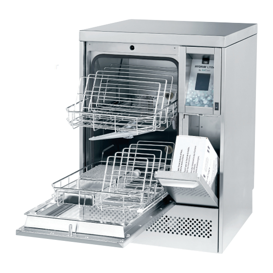
SciCan HYDRIM L110w G4 Service Manual
Instrument washer
Hide thumbs
Also See for HYDRIM L110w G4:
- Operator's manual (81 pages) ,
- Quick reference manual (2 pages) ,
- Operator's manual (41 pages)
Table of Contents
Advertisement
Advertisement
Table of Contents
Troubleshooting

Related Manuals for SciCan HYDRIM L110w G4


Summary of Contents for SciCan HYDRIM L110w G4
- Page 1 HYDRIM L110w G4 INSTRUMENT WASHER...
-
Page 2: Table Of Contents
Contents 1. Introduction ........4 3. Diagnostics and Troubleshooting ... 30 Overview ..........4 3.1 Using the service menu ......30 Unit at a glance ........5 3.2 Using the setup menu ......31 Front and rear of unit ......5 3.3 Using the user menu ...... - Page 3 63 EU Representative HYDRIM and STATIM are registered trademarks of SciCan Ltd. BRAVO, HIP, and SysTM are trademarks of SciCan Ltd. All other trademarks referred to SciCan GmbH in this manual are the property of their respective owners.
-
Page 4: Introduction
® This guide provides instructions for the servicing and repair of the HYDRIM L110w G4 Instrument Washer. Every attempt has been made to provide accurate, detailed instructions. HYDRIM L110w G4 instrument washer cycle description chart Total Time Water Cycle Prewash... -
Page 5: Unit At A Glance
1.2 HYDRIM Unit at a glance – front and rear... -
Page 6: Left And Right Of Unit
1. Introduction 1.2 HYDRIM Unit at a glance – left and right... -
Page 7: Specifications
(Model number, serial number etc.). The serial number plate is located at the bottom left on the rear panel of the HYDRIM L110w G4 unit. A small label is located on the left hand side of the chemical door. -
Page 8: Safety Information
SciCan shall not be liable for incidental, special or consequential damages caused by any maintenance or services performed on the HYDRIM L110w G4 by a third party or for the use of equipment or parts manufactured by a third party, including lost profits, any commercial loss, economic loss, or loss arising from personal injury. -
Page 9: Tools And Hardware
Reporting It is vital for SciCan to learn of any problem in the field. This information will help SciCan solve the problem quickly and improve product reliability in new units. -
Page 10: Disconnecting The Unit
1. Introduction The unit contains the following types of hardware: Phillips pan head self-tapping metal screws Phillips pan head stainless steel machine screws Hex socket pan head stainless steel machine screws Spring clamps Band / Gear clamps Cable ties 1.6 Disconnecting the unit To disconnect the unit, follow these steps: 1. -
Page 11: Shipping Instructions
1. Introduction 1.7 Shipping instructions The unit should be serviced on site. If it is necessary to send the unit back to the dealer, follow these instructions: from the system before shipping the unit. Waste water in the unit may contain biological contaminants. Use a mechanical means or absorbent material to siphon the contents from the sump. -
Page 12: Installation
(SD-429). Please review this prior to approving installation, download at mySciCan.com. If the HYDRIM L110w G4 is installed in a sterilization center, the manufacturer of the sterilization center should allow enough space at the top, back and both sides of the unit to facilitate installation, leveling, and service access to the unit. - Page 13 The unit must be connected to the water supply in accordance with all local and national plumbing codes. SciCan recommends a hard plumbing installation within 1.5m/5ft. of the unit. If additional distance is necessary, commercial grade plumbing hose must be used to minimize leaks.
-
Page 14: Setting Water Softener
1. Introduction 1.9 Setting the water softener Water Hardness Conversion and salt regeneration levels The HYDRIM L110w G4 is equipped with °dH Regen. a built-in water softening system that must (mg CaCO3 / Litre) be adjusted according to the local water hardness. -
Page 15: Setting The Language
1. Introduction IMPORTANT: The HYDRIM’s water softening system reduces the water hardness by taking out Calcium Carbonate. If the water testing results show that the water hardness is outside the unit's range of adjustment, or if other dissolved solids in the water cause stains or deposits on the instruments or chamber, an external water treatment system may be required. -
Page 16: Setting The Date
1. Introduction NOTE: If the HYDRIM is connected to a network, it is important to also enter the correct Time Zone. Enter the Time submenu, select Time Zone and scroll and select your local time zone. To change your unit to display 12-hour time format (24-hour time format is the default setting), go to the Setup menu and use to scroll to TIME 12/24, select it and toggle to 12. -
Page 17: Adjusting The Screensaver Delay
1. Introduction 1.15 Adjusting the screensaver delay To change the length of time before the screensaver is activated, follow these steps: Screensaver Scroll to and select. to scroll through your time options. When you have found the amount of time you require, press it. Press to save and return to the Setup menu. -
Page 18: Adjusting The Salt Regeneration
1. Introduction 1.19 Adjusting the salt regeneration Salt regeneration should be set according to the local water hardness. See section 1.8 Setting the water softener for instructions on determining correct settings. To set salt regeneration, follow these steps: Set Regeneration Scroll to and select. -
Page 19: Creating A User Name
1. Introduction 1.22 Creating a User Name Up to four unique User Names can be created. To assign a User Name follow these steps: User Scroll to and select. User Name To assign a user name, select and use the alphabetic keypad to enter a name (up to 12 characters) and press to save. -
Page 20: Setting Up Process Enforced Usage
1.25 Connecting to a network The HYDRIM L110w G4 has a 10/100Base-T Ethernet port located at the back of the unit. To connect your HYDRIM to a network using a router, follow these steps: 1. Connect your network cable to the Ethernet port at the back of the unit. If your office uses a router, the router should automatically assign the unit an IP address. -
Page 21: Connecting To A Wireless Network
1.26 Connecting to a wireless network The HYDRIM can be configured for wireless use by connecting the Ethernet port to an external wireless bridge / access point. SciCan currently recommends the use of the ® ®... -
Page 22: Routine Procedures And Maintenance
2. Routine Procedures and Maintenance 2.1 Replacing the cleaning solution To replace the cleaning solution, follow these steps: To prime the cleaning solution dosing pump, press the water softener/detergent icon on the main screen. In the water softener/detergent screen, press the red X next to “Detergent”. The unit will prime the dosing system and a green check mark will appear in place of the red X when it is ready for use. -
Page 23: Refilling The Water Softener
To add water softening salts, follow these steps: 1. Unscrew the salt container lid. 2. On first using the HYDRIM L110w G4, pour 1 liter (1 quart) of water into the salt container, or until it is full with water. NOTE: It is not necessary to add water during subsequent refills of the salt container. -
Page 24: Filter And Wash Arm Maintenance
2. Routine Procedures and Maintenance Removing and checking the wash arms If you see that the wash arms are not turning easily, remove them. Both the upper and lower arms are thread mounted. Turn the mounting ring counter clockwise to remove. Rinse under a tap, clear obstructions from outlet holes upper... -
Page 25: Cleaning The Chamber
2. Routine Procedures and Maintenance 2.4 Cleaning the chamber The HYDRIM L110w G4 chamber can be cleaned using the “Cleaning” program in the User menu. This cycle is used to periodically remove hardwater deposits from the chamber walls and racks. Pour 1 litre of vinegar into the chamber before starting the cycle. From the User menu, select “Cleaning”... -
Page 26: Using A Usb Drive With The Software
3. Copy the file `firmware.ini` file into the root directory of the USB drive. (eg. copy and paste the file `firmware.ini` from Z:\FIRMWARE\ to Z:\) 4. The USB drive is now ready to be reused to upgrade other Hydrim L110w G4 devices. -
Page 27: Using The Hydrim Remote Access Function
2.7 Using the HYDRIM remote access function Users can allow offsite technicians to remotely access the LCD touchscreens and web portals of HYDRIM L110w G4 units connected to a network. This can be done either from within a network or from outside a network. -
Page 28: Annual Service Requirements
Use your mouse to click and select touchscreen elements. 2.8 Annual Service Requirements The HYDRIM L110w G4 is designed to be maintenance free; however, it is recommended that a SciCan-approved service technician perform an annual check. The following checks are recommended in order to maintain optimum performance of the unit. - Page 29 2. Routine Procedures and Maintenance you can scroll through and check the functionality of the following components: be adjusted. Equipment and parts requirements for annual service...
-
Page 30: Diagnostics And Troubleshooting
3. Diagnostics and Troubleshooting 3.1 Using the service menu To access the service menu, select the image of the technician and enter the service code 7919 on the keypad. User Technician Setup Cycle Settings SW Upgrade Wash Test Set Regeneration Network Setup Chemical Setup Diagnostic Tools... -
Page 31: Using The Setup Menu
3. Diagnostics and Troubleshooting 3.2 Using the setup menu To access functions and settings on the setup menu, proceed as follows: User Technician Setup Language Selection Set Printer Remote Access Country Baud Rate Prepare for Shipping Date/Time Set EOL CR/LF Unit No. -
Page 32: Using The User Menu
3. Diagnostics and Troubleshooting 3.3 Using the user menu To access functions and settings on the user menu, proceed as follows: User Technician Setup Cleaning Set Drying Time Set Wash Time Cycle Count Process Enforced User... -
Page 33: Using Software Tools For Diagnostics
3. Diagnostics and Troubleshooting 3.4 Using software tools for diagnostics Within the service menu, there are two useful tools for troubleshooting: Debug screen and IO status screen. Debug Screen The Debug screen is used when running a cycle to view the I/O status of components. Active components are colored while inactive components remain white. -
Page 34: I/O Status Screen
3. Diagnostics and Troubleshooting I/O status screen The IO status screen is used when testing components and wires for functionality without the cycle running. Chm. Pres. Figure 10... -
Page 35: Troubleshooting Cycle Faults
3. Diagnostics and Troubleshooting 3.5 Troubleshooting cycle faults 3.5 Troubleshooting cycle faults Cycle Fault Effect Problem Possible Causes CF 1 Water Heating Improper wash, cycle Chamber temperature This is caused by a water aborted less than a set point heater malfunction: Failure after a timeout, Check water heater... - Page 36 3. Diagnostics and Troubleshooting Cycle Fault Effect Problem Possible Causes CF 9 Program Cycle interrupted The unit is running Defective PCB and/or a cycle for more than software failure Timeout 3h ±3 min. Replace Color LCD controller. CF 14 Water Too Hot Cycle interrupted During the Prewash phase Check water...
- Page 37 3. Diagnostics and Troubleshooting Cycle Fault Effect Problem Possible Causes Touchscreen is blank/ Check power source white USB storage device Re-insert the USB storage device and wait for the does not contain data to copy over again. If the last print out problem persists, back up all the information on the USB device and reformat it.
-
Page 38: Removing And Replacing Panels
PRECAUTIONS If you have questions about the unit you are repairing, please do not hesitate to contact your local SciCan representative for information. Also, the HYDR IM is heavy. Exercise caution and seek assistance when lifting or carrying units. EXERCISE CAUTION Hazardous voltages are accessible when the cover is removed. -
Page 39: Removing And Reinstalling The Top Panel
4. Removing and Replacing Panels 4.1 Removing and reinstalling the top panel 1. Turn the unit off, disconnect the power and open the door (Figure 11a) 2. Pull the top panel to the front and shift it left and right to release it from the tabs at the front. -
Page 40: Front Components
PRECAUTIONS If you have questions about the unit you are repairing, please do not hesitate to contact your local SciCan representative for information. Also, the HYDR IM is heavy. Exercise caution and seek assistance when lifting or carrying units. EXERCISE CAUTION Hazardous voltages are accessible when the cover is removed. -
Page 41: Removing And Reinstalling The Kickplate
5. Front Components 5.1 Removing and reinstalling the kickplate 1. Remove the screw at the center of the kickplate. (Figure 12a) 2. Insert a flat-blade screwdriver at the top to pry it back. 3. Disconnect the ground wire at right and remove. To reinstall, connect the ground wire, tip it back into position and fasten the center screw. -
Page 42: Removing And Reinstalling The Sump Temperature Sensor
5. Front Components 5.3 Removing and reinstalling the sump temperature sensor 1. Turn the unit off, disconnect the power and remove the kickplate, top and right panels. 2. Remove the coarse and fine filters inside the chamber. 3. Remove the mounting nut from the sensor inside the sump. 4. -
Page 43: Removing And Reinstalling The Chemical Dosing Valve
5. Front Components 5.4 Removing and reinstalling the chemical dosing valve reservoir A reservoir B 1. Disconnect the chemical pouch, run a “Prepare for shipping cycle” to drain system, turn the unit off, and disconnect the power cord. 2. Remove the kickplate, top and right panels. -
Page 44: Removing And Reinstalling The Chemical Reservoirs
5. Front Components 5.5 Removing and reinstalling the chemical reservoirs There are two dosing reservoirs, one with a plug (reservoir A) and the other with a switch (reservoir B). A must be removed before B. To remove reservoir A: 1. Disconnect the chemical pouch, run a “Prepare for shipping cycle” to drain system, turn the unit off, and disconnect the power cord. -
Page 45: Door Components
PRECAUTIONS If you have questions about the unit you are repairing, please do not hesitate to contact your local SciCan representative for information. Also, the HYDR IM is heavy. Exercise caution and seek assistance when lifting or carrying units. EXERCISE CAUTION Hazardous voltages are accessible when the cover is removed. -
Page 46: Removing And Reinstalling The Chamber Seal
6. Door Components 6.1 Removing and reinstalling the chamber seal 1. Before pulling the chamber seal, note how the bottom left and right edges touch the bottom of the chamber. 2. Pull the seal out from the seal recess. Figure 17a To reinstall: 1. -
Page 47: Removing And Reinstalling The Lower Door Seal
6. Door Components 6.2 Removing and reinstalling the lower door seal 1. Turn the unit off. 2. Remove the 4 screws on the plate at the base of the door on the inside. (Figure 18a) 3. Remove the lower door seal. Figure 18a screws To reinstall,... -
Page 48: Removing And Reinstalling The Door
6. Door Components 6.3 Removing and reinstalling the door 1. Turn the unit off. 2. Remove the 4 screws on each side. (Figure 19a) 3. Pull the door off. CAUTION: The right hinge is spring-loaded and will snap up. Figure 19a screws To reinstall: 1. -
Page 49: Removing And Reinstalling The Lower Door D-Seal
6. Door Components 6.4 Removing and reinstalling the lower door D-seal D-seal 1. Remove the door (See 6.3 Removing and reinstalling the door). 2. Remove the D-seal and remove any adhesive residue. Figure 20a To reinstall, press the D-seal into place, ensuring it is seated evenly, and reattach door. -
Page 50: Removing And Reinstalling The Door Springs
6. Door Components 6.6 Removing and reinstalling the door springs 1. Turn the unit off and disconnect the power. 2. Remove the top and right panels. 3. Ensure the door is closed. 4. Access the door springs from the right side to unhook. -
Page 51: Right Side Components
PRECAUTIONS If you have questions about the unit you are repairing, please do not hesitate to contact your local SciCan representative for information. Also, the HYDR IM is heavy. Exercise caution and seek assistance when lifting or carrying units. EXERCISE CAUTION Hazardous voltages are accessible when the cover is removed. -
Page 52: Removing And Reinstalling The Lcd Touchscreen And Lcd Controller
NOTE: When installing a new LCD controller board, you must manually assign the serial number and model number. For detailed instructions on how to do this, please contact SciCan technical service. To remove the LCD controller board: 1. Turn the unit off and disconnect the power. - Page 53 NOTE: When installing a new LCD controller board, you must manually assign the serial number and model number. For detailed instructions on how to do this, please contact SciCan technical service. LCD assembly - part # 01-113856S left Colour LCD controller, L110w – part # 01-113665S...
-
Page 54: Removing And Reinstalling The I/O Board
7. Right Side Components 7.2 Removing and reinstalling the I/O board screws screws Figure 24 1. Turn the unit off, disconnect from power and remove the top and right panel. 2. Disconnect all connectors on I/O board. 3. Remove the 5 screws fastening I/O board. To reinstall: 1. -
Page 55: Removing And Reinstalling The Power Supply
7. Right Side Components 7.3 Removing and reinstalling the power supply 1. Turn off the unit and disconnect the power cord. 2. Remove the wire contacts from the power supply. 3. Loosen the screw at the top left of the power supply bracket and remove the screw at the bottom right. -
Page 56: Removing And Reinstalling The Dosing Pump
7. Right Side Components 7.4 Removing and reinstalling the dosing pump 1. Disconnect the chemical pouch, run a “Prepare for shipping cycle” to drain system, turn the unit off, and disconnect the power cord. 2. Remove the kickplate and drain the detergent reservoirs using the drain tube. -
Page 57: Removing And Reinstalling The Chamber Level/Overflow Switch
7. Right Side Components 7.5 Removing and reinstalling the chamber level/overflow switch 1. Turn the unit off, disconnect the power and remove the top and right panels. 2. Remove the wiring from the switch. 3. Disconnect the tubing. 4. Remove the screw fastening the switch bracket to the unit and remove the switch and bracket. -
Page 58: Removing And Reinstalling The Drain Pump And Exhaust Assembly
7. Right Side Components 7.6 Removing and reinstalling the drain pump and exhaust assembly exhaust bracket exhaust hose exhaust assembly check valve Figure 28a exhaust bracket 1. Turn the unit off and disconnect the power. CAUTION: Water will remain in the drain assembly. Suction out any remaining water. -
Page 59: Removing And Reinstalling The Dryer Motor
7. Right Side Components 7.7 Removing and reinstalling the dryer motor 1. Turn the unit off, disconnect the power and remove the top cover and right panel. 2. Remove the 2 screws on dryer motor bracket to release the dryer motor. 3. -
Page 60: Removing And Reinstalling The Power Switch
7. Right Side Components 7.8 Removing and reinstalling the power switch 1. Turn off the unit and disconnect the power. 2. Remove the screw above the LCD touchscreen. 3. Open the service panel. 4. Disconnect the wires from the power switch and press down the locking tabs to remove, pushing the switch through the panel. -
Page 61: Left Side Components
PRECAUTIONS If you have questions about the unit you are repairing, please do not hesitate to contact your local SciCan representative for information. Also, the HYDR IM is heavy. Exercise caution and seek assistance when lifting or carrying units. EXERCISE CAUTION Hazardous voltages are accessible when the cover is removed. -
Page 62: Removing And Reinstalling The Sump Water Heater
8. Left Side Components 8.1 Removing and reinstalling the sump water heater 1. Turn the unit off and disconnect the power. CAUTION: Water will remain in the drain assembly. Suction out any remaining water. 2. Remove the top cover and left panel. 3. -
Page 63: Removing And Reinstalling The Recirculation Pump
8. Left Side Components 8. Left Side Components 8.2 Removing and reinstalling recirculation pump 1. Turn the unit off and disconnect the power. CAUTION: Water will remain in the drain assembly. Suction out any remaining water. 2. Remove the top, rear and left panels. 3. -
Page 64: Rear Components
PRECAUTIONS If you have questions about the unit you are repairing, please do not hesitate to contact your local SciCan representative for information. Also, the HYDR IM is heavy. Exercise caution and seek assistance when lifting or carrying units. EXERCISE CAUTION Hazardous voltages are accessible when the cover is removed. -
Page 65: Removing And Replacing The Ethernet And Rs232 Ports
9. Rear Components 9.1 Removing and reinstalling the Ethernet and RS232 ports 1. Disconnect the power and remove the top cover and back panel. 2. To remove Ethernet port, remove the screw on the left of the port, disengage the tab from the bracket, and disconnect the wiring from the I/O board. -
Page 66: Removing And Reinstalling The Water Softener System
9. Rear Components 9.3 Removing and reinstalling the water softener system 1. Turn unit off and disconnect power. 2. Remove the top, rear and left panels. 3. From inside the chamber, remove cap and siphon remaining water from water softener system. wire. -
Page 67: Removing And Reinstalling The Air Break
9. Rear Components 9.4 Removing and reinstalling the air break air break 1. Turn the unit off and disconnect the power. 2. Remove top and rear panels. 3. Remove the air break bracket. 4. Number the hoses according to the numbers embossed on the air break. -
Page 68: Removing And Reinstalling The Water Inlet Valves
9. Rear Components 9.5 Removing and reinstalling the water inlet valves 1. Turn the unit off and disconnect the power. 2. Remove the top, right and rear panels. hot water inlet 3. Valves for hot water, cold water and R/O water inlets can be accessed from the rear and right side of the unit. -
Page 69: Removing And Reinstalling The Fuses And Fuse Holders
9. Rear Components 9.6 Removing and reinstalling the fuses and fuse holders 1. Turn the unit off, disconnect the power and remove top and rear panels. 2. For continued protection against the risk of fire, replace fuses with 15A, 250V type F only. 3. -
Page 70: Spare Parts & Accessories
10. Spare Parts & Accessories This spare part list was last updated on the date of the release of the unit. To see an updated spare part list, please refer to my.scican.com. 01-113830S AirBreak, L110w G4 01-113831S Breather Check Valve, L110w/M2 G4... - Page 71 Screw, Back Cover & Service Door, K 01-111485S Screw, Kickplate Hydrim L110w/M2/G4 01-111483S Screw, Top Cover Hydrim L110/M2/G4 01-113848S Trolley, Lower Hydrim L110w G4 01-113850S Trolley, Upper Hydrim L110w/M2 G4 01-113851S Tubing Drain Hydrim L110w G4 01-109790S Upper Spray Arm Hydrim...
- Page 72 10. Spare Parts & Accessories This accessory part list was last updated on the date of the release of the unit. To see an updated spare part list, please refer to my.scican.com. 01-109965S 4XL Cassette Rack, 1/1, HydrimL/M2 01-109963S 5 Cassette Rack, 1/1, HydrimL/M2...
-
Page 73: Appendices
11. Appendix A HYDRIM L110w G4 Electrical Schematic... -
Page 74: Appendix B Hydrim L110W G4 Flow Diagram
11. Appendix B HYDRIM L110w G4 Flow Diagram...
Need help?
Do you have a question about the HYDRIM L110w G4 and is the answer not in the manual?
Questions and answers