Table of Contents
Advertisement
Advertisement
Table of Contents

Related Manuals for TagMaster XT-1


Summary of Contents for TagMaster XT-1
- Page 1 XT-1 / XT Mini Manual...
- Page 2 Caution: To comply with Council Recommendation 1999/519/EC and FCC regulations, this reader must be installed to provide a separation distance of at least 25 cm (XT-1) or 20 cm (XT Mini) from all persons and must not be co-located or operating in conjunction with any other antenna or transmitter.
-
Page 3: Table Of Contents
XT-1/XT Mini Manual 13-111 05, 2015-08-14 Table of Contents Introduction Readers ......................5 Tags ......................5 ® SecureMarkID ....................5 Installation Safety Instructions ..................5 Reader and Tag Placement ................6 Mounting Instructions ..................8 2.3.1 Universal Mounting Kit (UMK) ..............8 2.3.2... - Page 4 XT-1/XT Mini Manual 13-111 05, 2015-08-14 Connecting to an External System Wiegand/Magstripe ..................24 5.1.1 Easy Configuration ................... 24 OSDP (RS485) .................... 27 5.2.1 Easy Configuration ................... 27 Push (RS232, RS485, TCP/IP) ..............28 TAGP (TCP/IP) .................... 28 Other Protocols .................... 28...
-
Page 5: Introduction Readers
Tags EPC Gen 2 tags are typically passive, which means that they draw power from the reader's electromagnetic field instead of having a battery. XT-1 and XT Mini support all UHF tags that comply with the EPC Gen 2 ®... -
Page 6: Reader And Tag Placement
Figure 3 shows two installations with side-mounted readers. A. XT Mini is optimal for parking access with moderate read range requirements. B. A side-mounted XT-1 can be used to cover a wide road. Figure 3 Side-mounted reader (A: XT Mini, B: XT-1) - Page 7 Typical tags do not work if they are mounted on metal or objects containing water. Metallized Figure 4 XT-1 radiation pattern windshields may prevent tag reading as they block radio waves. Most EPC Gen 2 tags have a donut shaped radiation pattern as shown in Figure 5. This means that the tags can be read not only when the front side is facing the reader, but also when the backside or long edges are facing the reader.
-
Page 8: Mounting Instructions
[1] for more details in on installation. Figure 6 Universal Mounting Kit (UMK) 2.3.2 Dimensions Reader dimensions are shown in Figure 7 (XT-1 to the left, XT Mini to the right). Figure 7 Reader Dimensions in [inch] and mm Page 8 of 32... -
Page 9: Cable Connections
2.4.1 XT-1 In XT-1, cables should primarily be connected through the central M20 cable gland. This cable gland can be used with one cable (Ø 6-12 mm) or two cables (Ø 2-6 mm) using the supplied insert. As an alternative, one or more of the four M16 blind plugs can be replaced with cable glands. -
Page 10: Wire Connections
XT-1/XT Mini Manual 13-111 05, 2015-08-14 Wire Connections 2.5.1 Spring Cage Terminals With the exception of Ethernet and USB, all wires are connected to spring cage terminals. These terminals are easy to use and work with both solid and stranded wires. -
Page 11: Interfaces Overview
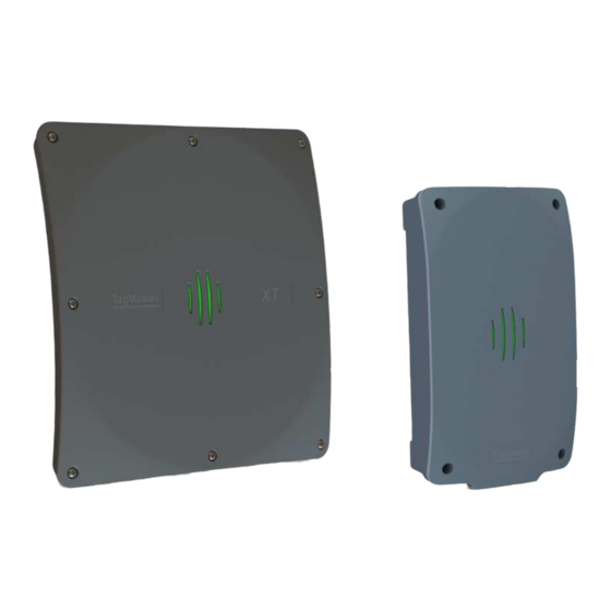
3 Interfaces Overview Figure 10 shows the locations of the different interfaces in XT-1 and XT Mini. The name of each interface is listed in Table 2. The following sections refer to the interfaces as named in the table. Figure 10 XT-1 (left) and XT Mini (right) interfaces... -
Page 12: Wiegand/Magstripe
XT-1/XT Mini Manual 13-111 05, 2015-08-14 Wiegand/Magstripe The reader has a software configurable Wiegand/Magstripe interface. WIEG:D0 Wiegand 0 WIEG:D1 Wiegand 1 Connections (Wiegand) WIEG:CL Card load WIEG:GND Signal ground #1 MAG:CLK Magstripe clock Connections MAG:DATA Magstripe data (Magstripe) MAG:LOAD Card load... -
Page 13: Wiegand Timing
XT-1/XT Mini Manual 13-111 05, 2015-08-14 W37N/H10302 37-bit Wiegand (35-bit data, no site code): S101 EDDDDDDDDDDDDDDDDDDDDDDDDDDDDDDDDDDDO XXXXXXXXXXXXXXXXXXX------------------ ------------------XXXXXXXXXXXXXXXXXXX W37R/H10302 37-bit Wiegand (37-bit data, no site code, no parity): S101 DDDDDDDDDDDDDDDDDDDDDDDDDDDDDDDDDDDDD M8N/H10320 8-digit Magstripe: S101 [25 zeroes]BDDDDDDDDFL[165 zeroes] Table 5 Wiegand/Magstripe formats Using DIP switches S301:6-8 it is possible to activate 1 kΩ... -
Page 14: Magstripe Timing
Figure 13 Magstripe timing diagram (note: data low = logic one) Ethernet The reader has a 10 Mbps/100 Mbps Ethernet interface with one (XT Mini) or two (XT-1) ports. The interface supports auto crossover (Auto-MDIX) so that installation can be done using either patch cables or crossover cables. -
Page 15: Rs232
PC that is directly connected to a reader will usually get an IP address in this subnet automatically. The built-in Ethernet switch (XT-1 only) makes it possible to connect multiple readers in a chain. Figure 14 Readers connected in a chain using the built-in Ethernet switch The reader supports ICMP echo request/reply (ping) to simplify network troubleshooting. -
Page 16: Rs485
When using RS485 communication, correct termination of the interface should be considered in order to handle transmission-line effects. The XT-1 has a built-in option (DIP S301:3 ON) of 120 Ω termination on the receive side (to be used at each end of the RS485 chain), and an option (DIP S301:4-5 ON) of 620 Ω... -
Page 17: Inputs
XT-1/XT Mini Manual 13-111 05, 2015-08-14 Inputs The reader has 3 opto-coupled inputs. INPUTS:IN1+ Input 1 positive terminal INPUTS:IN1- Input 1 negative terminal INPUTS:IN2+ Input 2 positive terminal Connections INPUTS:IN2- Input 2 negative terminal INPUTS:IN3+ Input 3 positive terminal INPUTS:IN3-... -
Page 18: Relay
XT-1/XT Mini Manual 13-111 05, 2015-08-14 Relay The relay output can be used to control a barrier, gate, or other object. The relay can either be activated when any tag has been read or when an accepted tag has been read. A tag is considered accepted when it is listed in the built-in access controller's database. -
Page 19: Dip Switches
XT-1/XT Mini Manual 13-111 05, 2015-08-14 DIP Switches Two 8-position DIP switches are available for interface and software configuration. 3.13.1 Interface Configuration DIP Switch (S301) Position(s) Description RS485 2-wire mode S301 S301:1 ON = TX+ connected to RX+ S301:2 ON = TX– connected to RX–... -
Page 20: Configuration Web Interface
Note that the web interface may look slightly different depending on the version of the firmware in the reader. Up-to-date documentation is always available under "Documentation" in the web interface menu. 4.1.1 Start The "Start" page provides TagMaster contact information. 4.1.2 Information The "Information" page provides information about the system. -
Page 21: Settings
XT-1/XT Mini Manual 13-111 05, 2015-08-14 4.1.3 Settings… All configuration of the reader can be done on the "Settings…" pages. For all settings, it is possible to get help by clicking on the question mark ( ). Click the "Save Settings" button to activate changed settings. -
Page 22: Region
XT-1/XT Mini Manual 13-111 05, 2015-08-14 Region To meet different radio regulations around the world, the reader can be configured to work in different regions. Each reader model comes in two versions: EU and US. Each reader version supports a number of regions as listed in the table below. -
Page 23: Data Selection
XT-1/XT Mini Manual 13-111 05, 2015-08-14 The TAGP protocol reports tag events as they come out of the tag filter. 4.3.5 Data Selection The "Data selection" settings (under Settings…/Data Selection in the web interface) specifies how the read data shall be interpreted (binary, hexadecimal or decimal) and also makes it possible to select a part of the data (number of digits with a left or right aligned offset). -
Page 24: Connecting To An External System
XT-1/XT Mini Manual 13-111 05, 2015-08-14 5 Connecting to an External System The following sections describe how to connect the reader to another system. Note that the reader requires more power than a typical proximity reader and should have its own power supply. - Page 25 XT-1/XT Mini Manual 13-111 05, 2015-08-14 AXIS A1001 5.1.1.2 Configure A1001 to use reader protocol Wiegand with "Dual LED" and set the card format to H10302. [READER I/O] - IN1+ [READER I/O] 12V CL/LOAD IN1- [READER I/O] IO5 D0/CLK [READER DATA] D0...
- Page 26 XT-1/XT Mini Manual 13-111 05, 2015-08-14 Paxton Net2 Plus 5.1.1.5 Configure the Paxton system to use reader type "Clock & Data". IN1+ CL/LOAD IN1- Green LED D0/CLK Clock/D1 IN2+ D1/DATA Data/D0 IN2- Red LED S101 - Magstripe format: M8N/H10320 S301 - Vigilant pull-ups disabled...
-
Page 27: Osdp (Rs485)
XT-1/XT Mini Manual 13-111 05, 2015-08-14 OSDP (RS485) The reader supports the Open Supervised Device Protocol (OSDP) [4] for connection to access control systems. OSDP communicates over 2-wire RS485 and can therefore be used with long cables and does not require extra cables for LED and buzzer control. The DIP switch S301:1-2 must be set to ON to enable 2-wire mode on the reader. -
Page 28: Push (Rs232, Rs485, Tcp/Ip)
SecureMarkID tags and hexadecimal for other tags. TAGP (TCP/IP) TagMaster Readers can be controlled and monitored using a protocol called TAGP. The TAGP protocol is human readable and can be used over TCP/IP, RS232 and RS485. A terminal emulation program such as PuTTY is all that is required to interact with TAGP. -
Page 29: Built-In Access Controller
XT-1/XT Mini Manual 13-111 05, 2015-08-14 6 Built-in Access Controller The reader has a built-in access controller that can control a barrier or gate using the reader's relay output. All accesses can be logged. A presence indicator such as an inductive loop can be connected to input 3. -
Page 30: Troubleshooting
Line feed Original equipment manufacturer RFID Radio-frequency identification Personal computer ® SecureMarkID A TagMaster implementation for improved Security using EPC tags TAGP A TagMaster protocol for RFID reader communication TCP/IP An Internet protocol suite Universal mounting kit Universal serial bus... -
Page 31: Technical Specification
3 isolated outputs shared with Wiegand/Magstripe Relay 1 relay output 60VDC, 2A Interfaces RS232, RS485, Wiegand/Magstripe, Ethernet (2 ports on XT-1), USB service Interface, Tamper switches (XT Mini only) Certificates CE Certificate according to R&TTE-directive 1999/5/EC and FCC RoHS Directive 2002/95/EC and 2011/65/EU... - Page 32 Technical Support Phone: +46 8 632 19 50 E-mail: support@tagmaster.com Office Address TagMaster AB Kronborgsgränd 11 164 46 KISTA SWEDEN Phone: +46 8 632 19 50 Web: www.tagmaster.com...
Need help?
Do you have a question about the XT-1 and is the answer not in the manual?
Questions and answers