Table of Contents
Advertisement
Advertisement
Table of Contents

Related Manuals for TagMaster XT-1


Summary of Contents for TagMaster XT-1
- Page 1 XT-1 Installation Manual...
- Page 2 TagMaster AB. Disclaimer While effort has been taken to ensure the accuracy of the information in this document TagMaster AB assumes no responsibility for any errors or omissions, or for damages resulting from the use of the information contained herein.
-
Page 3: Table Of Contents
XT-1 Installation Manual 13-111 02, 2014-RO-012, 2014-04-30 Table of Contents Introduction Overview......................4 Tags ......................4 ® Security and SecureMarkID ................. 4 Installation Safety Instructions ..................4 Mounting Instruction ..................5 2.2.1 General ...................... 5 2.2.2 Dimensions ....................6 Interfaces Cables ...................... -
Page 4: Introduction Overview
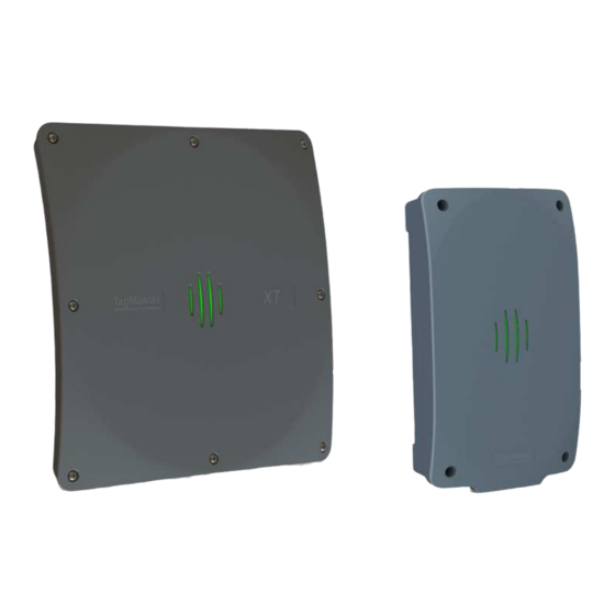
1 Introduction Overview The XT-1 is an UHF RFID reader compliant with EPC Gen 2 (ISO 18000-6C). The reader is specifically tailored for Automatic Vehicle Identification (AVI) applications such as Parking, Gated Communities and Condominiums. It has been designed to provide absolutely premium performance for read-range and environmental specifications while also giving a large number of interface options and having an innovative implementation for TCP/IP connectivity and monitoring. -
Page 5: Mounting Instruction
Figure 1 Reading lobe The UMK (Universal Mounting Kit, Part No. 193600), see Figure 2, from TagMaster enables the reader to be mounted in a wide variety of positions and angles. The kit contains all parts needed for mounting the reader on a wall or on a pole. -
Page 6: Dimensions
XT-1 Installation Manual 13-111 02, 2014-RO-012, 2014-04-30 2.2.2 Dimensions Figure 3 XT-1 Dimensions Page 6 of 32... -
Page 7: Interfaces Cables
(6-12 mm) or by using the supplied insert with two cables (2-6 mm), see Figure 5. 2. Open XT-1 lid by loosening the 8 screws on the front, and slide the lid open (see Figure 6 for reader with lid in open position). - Page 8 13-111 02, 2014-RO-012, 2014-04-30 Figure 5 The XT-1 M20 cable gland with insert for 2 cables Never remove or use the ventilating membrane (Figure 6, Pos. 2) on the back of the XT-1 for cable connections. Figure 6 XT-1 overview (Pos. 1 is ground screw connection, Pos.2 is ventilating membrane)
-
Page 9: Wires
XT-1 Installation Manual 13-111 02, 2014-RO-012, 2014-04-30 Wires 3.2.1 Terminal Connections Wire connections (with the exception of Ethernet and USB, see §3.2.2) are added as single wires to spring cage terminal connectors, see Figure 7. These are easy-to-use terminals for single solid or stranded wires. -
Page 10: Power Supply
13-111 02, 2014-RO-012, 2014-04-30 Power Supply The XT-1 shall be powered by an isolated power supply suitable for outdoor use. The required voltage is 12 VDC to 24 VDC. It is recommended to use a power supply of 24 VDC, 0.5 A minimum. -
Page 11: Wiegand/Magstripe
13-111 02, 2014-RO-012, 2014-04-30 Wiegand/Magstripe The XT-1 has a software configurable Wiegand/Magstripe interface. The interface has 1500 VDC isolation and overvoltage protection. The software functionality is described in §4.2.3.3.2. Using DIP switch S301:6-8 it is possible to activate 1 kΩ pull-up resistors on D0/CLK, D1/DATA and CL/LOAD. -
Page 12: Wiegand Timing
XT-1 Installation Manual 13-111 02, 2014-RO-012, 2014-04-30 3.4.1 Wiegand Timing The following values apply when all outputs are pulled up to 5 V with 1 kΩ resistors. Symbol Parameter Unit µs CL to D# setup time Fall time (all signals) µs... -
Page 13: Ethernet
1500 VDC. The default IP address of the device is unique among XT-1 readers and can be found on the label on the back of the XT-1. This makes it possible to create a stand-alone network without changing any reader network settings. -
Page 14: Rs232
The default output of the RS232 interface is tag data in ASCII format. If SecureMarkID® tags from TagMaster are being used (recommended) the numeric identity is sent out. If other EPC tags are being used the default output is the EPC data. The data is followed by CR+LF ('\r''\n'). -
Page 15: Rs485
When using RS485 communication, correct termination of the interface should be considered in order to handle transmission-line effects. The XT-1 has a built-in option (DIP S301:3 ON) of 120 Ω termination on the receive side (to be used at each end of the RS485 chain), and an option (DIP S301:4-5 ON) of 620 Ω... - Page 16 The default output of the RS485 interface is tag data in ASCII format. If SecureMarkID® tags from TagMaster are being used (recommended) the numeric identity is sent out. If other EPC tags are being used the default output is the EPC data. The data is followed by CR+LF ('\r''\n').
-
Page 17: Inputs
13-111 02, 2014-RO-012, 2014-04-30 Inputs The XT-1 has 3 software configurable inputs. The inputs are opto-coupled, have 1500 VDC isolation and reverse polarity protection. The inputs are activated by a current flow and the input impedance is 1 kΩ. A schematic view of an input is shown in Figure 18. -
Page 18: Relay
13-111 02, 2014-RO-012, 2014-04-30 Relay The XT-1 has a non-latching relay available. It is typically connected to the logic controlling a barrier, gate or other object when the reader is in stand-alone operation. Figure 19 Relay connections, overview and detail... -
Page 19: Usb
XT-1 Installation Manual 13-111 02, 2014-RO-012, 2014-04-30 The XT-1 has one USB type B connector, and acts like a USB 2.0 Full-Speed (12 Mbps) device. This interface is only intended for service and maintenance. The interface is connected using a standard cable to a USB port of a PC. -
Page 20: Dip Switches
See §4.4 for more information. Easy configuration S101 S101:6-8 are used for easy configuration of Wiegand/Magstripe and other settings when using XT-1 with an access control system. See §4.1 for more information. Table 12 Software Configuration DIP Switch (S101) Page 20 of 32... -
Page 21: Light And Sound
13-111 02, 2014-RO-012, 2014-04-30 Light and Sound The XT-1 is equipped with bright LEDs for external signalling (see Figure 23). These can indicate red/green/yellow based on firmware settings. A buzzer is also available and the default setting is off. Figure 23 LED, overview MicroSD Memory Card Slot The XT-1 is equipped with a microSD memory card slot for additional storage (see Figure 24). -
Page 22: Configuration Easy Configuration
4 Configuration Easy Configuration XT-1 can be configured to work with common access control systems using DIP switches S101:6-8. When any of these switches are in the ON position, the reader is configured to report tags once, accept SecureMarkID tags only, and use the specified Wiegand/Magstripe format. -
Page 23: Web Interface
13-111 02, 2014-RO-012, 2014-04-30 Web Interface XT-1 has a web interface for configuration and maintenance. The web interface is designed and tested to work with Google Chrome 34, Microsoft Internet Explorer 10, and Mozilla Firefox 28. Before it is possible to connect to the web interface, the PC's IP address and subnet mask must be changed. -
Page 24: Start
XT-1 Installation Manual 13-111 02, 2014-RO-012, 2014-04-30 4.2.1 Start The "Start" page provides TagMaster contact information. 4.2.2 Information The "Information" page provides information about the system. 4.2.3 Settings All configuration of the reader can be done on the "Settings…" pages. For all settings, it is possible to get help by clicking on the question mark ( ). - Page 25 XT-1 Installation Manual 13-111 02, 2014-RO-012, 2014-04-30 W34N 34-bit Wiegand (32-bit data, no site code): S101 EDDDDDDDDDDDDDDDDDDDDDDDDDDDDDDDDO XXXXXXXXXXXXXXXXX----------------- -----------------XXXXXXXXXXXXXXXXX W37N/H10302 37-bit Wiegand (35-bit data, no site code): S101 EDDDDDDDDDDDDDDDDDDDDDDDDDDDDDDDDDDDO XXXXXXXXXXXXXXXXXXX------------------ ------------------XXXXXXXXXXXXXXXXXXX W37R/H10302 37-bit Wiegand (37-bit data, no site code, no parity):...
-
Page 26: Web Tools
XT-1 Installation Manual 13-111 02, 2014-RO-012, 2014-04-30 EPC channel mask Sets which frequencies that shall be used in EU readers (not applicable in US readers). EPC memory bank Specifies which parts of the EPC tag to read. The default setting (EPC/SecureMarkID) makes it possible to read both EPC tags and SecureMarkID tags. -
Page 27: Documentation
XT-1 Installation Manual 13-111 02, 2014-RO-012, 2014-04-30 4.2.5 Documentation The Documentation page provides up-to-date reader documentation. 4.2.6 Reboot The Reboot page makes it easy to reboot the reader. • Press the "Reboot" button to initiate a reboot. • Wait for the reboot to complete. -
Page 28: Tagp Communication Protocol
13-111 02, 2014-RO-012, 2014-04-30 5 TAGP Communication Protocol TagMaster Readers can be controlled and monitored using a protocol called TAGP. The TAGP protocol is human readable and can be used over TCP/IP, RS232 and RS485. A terminal emulation program such as PuTTY is all that is required to interact with TAGP. -
Page 29: Troubleshooting
To facilitate troubleshooting, consider the following: Make sure that the XT-1 has correct supply voltage and sufficient current. Check the small green LED on the right side of the controller board inside the reader. When the LED is flashing (once per second) the reader is powered and the firmware is running. -
Page 30: Technical Specification
9 Technical Specification Operating frequencies XT-1 eu: 865.6-867.6 MHz Europe, XT-1 us: 902-928 MHz US, Americas Read range Up to 8 meters (26ft) with TagMaster UHF tags with SecureMarkID®; Windshield ID-tag and ISO-Card ID-tag Dimensions 300x300x60 mm (11.8x11.8x2.4 in) Weight 2.3 kg (5.1 lbs) - Page 31 XT-1 Installation Manual 13-111 02, 2014-RO-012, 2014-04-30 Page 31 of 32...
- Page 32 XT-1 Installation Manual 13-111 02, 2014-RO-012, 2014-04-30 Technical Support Phone: +46 8 632 19 50 Fax: +46 8 750 53 62 E-mail: support@tagmaster.com Office Address TagMaster AB Kronborgsgränd 11 SE-164 46 KISTA SWEDEN Phone: +46 8 632 19 50 Fax: +46 8 750 53 62 E-mail: sales@tagmaster.com...
Need help?
Do you have a question about the XT-1 and is the answer not in the manual?
Questions and answers