
Related Manuals for Dell PowerEdge FC640


Summary of Contents for Dell PowerEdge FC640
- Page 1 Dell EMC PowerEdge FC640 Installation and Service Manual Regulatory Model: E02B Series Regulatory Type: E02B005...
- Page 2 A WARNING indicates a potential for property damage, personal injury, or death. Copyright © 2017 Dell Inc. or its subsidiaries. All rights reserved. Dell, EMC, and other trademarks are trademarks of Dell Inc. or its subsidiaries. Other trademarks may be trademarks of their respective owners.
-
Page 3: Table Of Contents
Contents 1 PowerEdge FC640 system overview......................7 Front view of the system..............................7 Health status indicator..............................8 Drive indicator codes..............................9 iDRAC Direct LED indicator codes..........................10 Locating the Service Tag of your system........................ 10 2 Documentation resources..........................11 3 Technical specifications..........................13 System dimensions................................ - Page 4 System BIOS................................25 iDRAC Settings utility..............................45 Device Settings................................45 Dell Lifecycle Controller..............................45 Embedded system management..........................45 Boot Manager.................................. 45 Viewing Boot Manager..............................46 Boot Manager main menu............................46 One-shot BIOS boot menu............................46 System Utilities................................46 PXE boot................................... 47 6 Installing and removing system components....................48 Safety instructions................................48...
- Page 5 7 Using system diagnostics..........................101 Dell Embedded System Diagnostics..........................101 Running the Embedded System Diagnostics from Boot Manager..............101 Running the Embedded System Diagnostics from the Dell Lifecycle Controller..........101 System diagnostic controls............................. 102 8 Jumpers and connectors..........................103 System board jumpers and connectors........................103 System board jumper settings............................
- Page 6 Quick Resource Locator for the PowerEdge FC640 system................107 Contents...
-
Page 7: Poweredge Fc640 System Overview
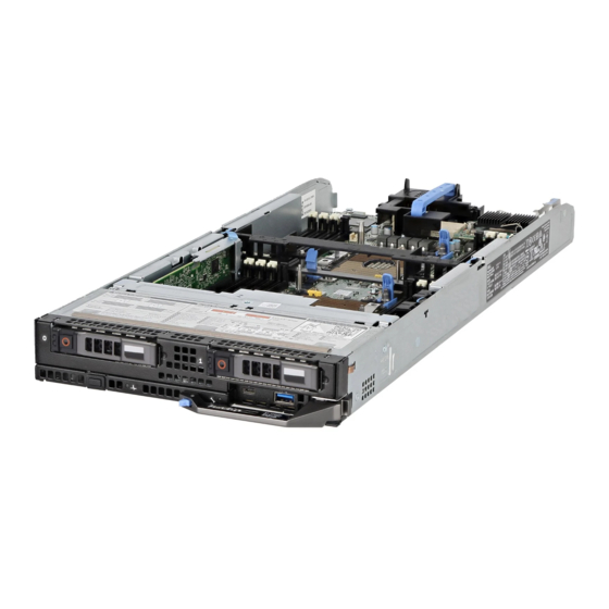
PowerEdge FC640 system overview The PowerEdge FC640 is a half-height sled supported on the PowerEdge FX/FX2 enclosure and supports up to : • Two Intel Xeon Processor Scalable Family processors • 2 x 2.5 inch hard drives or SSDs •... -
Page 8: Health Status Indicator
Identify mode is enabled (regardless of system errors)—system is in the process of identifying the system. Solid amber System is in failsafe mode—system is not ready or available and cannot be turned on. Flashes amber Errors present in the system. PowerEdge FC640 system overview... -
Page 9: Drive Indicator Codes
Predicted drive failure. Flashes amber four times per second Drive failed. Flashes green slowly Drive rebuilding. Solid green Drive online. Flashes green for three seconds, amber for three seconds, and Rebuild stopped. then turns off after six seconds PowerEdge FC640 system overview... -
Page 10: Idrac Direct Led Indicator Codes
You can identify your system using the unique Express Service Code and Service Tag. The service tag information is available on a sticker on the chassis of the system. This information is used by Dell EMC personnel to route support calls to the appropriate personnel. -
Page 11: Documentation Resources
Managing your system For information about systems management Dell.com/openmanagemanuals software offered by Dell, see the Dell OpenManage Systems Management Overview Guide. For information about setting up, using, and Dell.com/openmanagemanuals troubleshooting OpenManage, see the Dell OpenManage Server Administrator User’s Guide. - Page 12 Working with the Dell For information about understanding the features Dell.com/storagecontrollermanuals PowerEdge RAID controllers of the Dell PowerEdge RAID controllers (PERC), Software RAID controllers, or BOSS card and deploying the cards, see the Storage controller documentation. Understanding event and error For information about checking the event and error Dell.com/openmanagemanuals...
-
Page 13: Technical Specifications
• Video specifications • Environmental specifications System dimensions Figure 5. System dimensions Table 6. System dimensions of the Dell EMC PowerEdge FC640 system System Z (handle closed) Dell EMC PowerEdge FC640 197.9 mm (7.79 inches) 50.35 mm (1.98 inches) 544.32 mm (21.42 inches) -
Page 14: System Weight
• 64 GB quad rank (LRDIMMs) Storage controller specifications The PowerEdge FC640 system supports PowerEdge RAID Controller (PERC) H330, PERC H730P, S140 (SATA and NVMe drives) and Boot Optimized Server Storage (BOSS M.2). Drive specifications Hard drives The PowerEdge FC640 system supports up to two 2.5-inch, hot-swappable SAS/SATA hard drives, SSDs, or PCIe NVMe drives. -
Page 15: Internal Dual Sd Module
The micro USB 2.0-compliant port on the front of the system can only be used as an iDRAC Direct or a management port. Internal Dual SD Module The PowerEdge FC640 system supports two internal micro SD cards dedicated for the hypervisor. This card offers the following features: •... -
Page 16: Particulate And Gaseous Contamination Specifications
Table 12. Maximum vibration specifications Maximum vibration Specifications Operating 0.26 G at 5 Hz to 350 Hz (all operation orientations). Storage 1.87 G at 10 Hz to 500 Hz for 15 min (all six sides tested). Table 13. Maximum shock specifications Maximum shock Specifications Operating... -
Page 17: Standard Operating Temperature
Particulate contamination Specifications NOTE: Air entering the data center must have MERV11 or MERV13 filtration. Conductive dust Air must be free of conductive dust, zinc whiskers, or other conductive particles. NOTE: This condition applies to data center and non-data center environments. - Page 18 • NEBS SKU processors higher than 85 W are not supported. • Peripheral cards and /or peripheral cards greater than 25 W, that are not verified by Dell, are not supported. Thermal Restriction matrix Table 20. Thermal restrictions matrix Thermal Design Power (TDP)
- Page 19 Thermal Design Power (TDP) Core count Processors Ambient restriction for the processor 125W 6130T 125W 6126T 105W 5120T 5119T C40** E45*** 4116T C40** E45*** 4114T C40** E45*** 4109T C40** E45*** * DIMM limit 1 – Max 64 GB LRDIMMs. No 128 GB, No AEP(Apache Pass). This is applicable only for systems with dual processors. **C indicates that the processor is continuously operating at the specified temperature or lower.
-
Page 20: Initial System Setup And Configuration
The Integrated Dell Remote Access Controller (iDRAC) is designed to make system administrators more productive and improve the overall availability of Dell systems. iDRAC alerts administrators to system issues, helps them perform remote system management, and reduces the need for physical access to the system. -
Page 21: Log In To Idrac
Ensure that you change the default user name and password after setting up the iDRAC IP address. For more information about logging in to the iDRAC and iDRAC licenses, see the latest Integrated Dell Remote Access Controller User's Guide at Dell.com/idracmanuals. -
Page 22: Downloading Drivers And Firmware
Using Dell OpenManage Deployment Toolkit (DTK) Dell.com/openmanagemanuals Downloading drivers and firmware Dell recommends that you download and install the latest BIOS, drivers, and systems management firmware on your system. Prerequisite Ensure that you clear the web browser cache before downloading the drivers and firmware. -
Page 23: Pre-Operating System Management Applications
You can manage basic settings and features of a system without booting to the operating system by using the system firmware. Topics: • Options to manage the pre-operating system applications • System Setup • Dell Lifecycle Controller • Boot Manager • PXE boot Options to manage the pre-operating system applications Your system has the following options to manage the pre-operating system applications: •... -
Page 24: Viewing System Setup
The iDRAC settings utility is an interface to set up and configure the iDRAC parameters by using UEFI (Unified Extensible Firmware Interface). You can enable or disable various iDRAC parameters by using the iDRAC settings utility. For more information about this utility, see Integrated Dell Remote Access Controller User’s Guide at Dell.com/idracmanuals. -
Page 25: System Bios
System BIOS You can use the System BIOS screen to edit specific functions such as boot order, system password, setup password, set the SATA and PCIe NVMe RAID mode, and enable or disable USB ports. Related link System BIOS Settings details Boot Settings Network Settings System Information... -
Page 26: System Information
Option Description Network Settings Specifies options to manage the UEFI network settings and boot protocols. Legacy network settings are managed from the Device Settings menu. Integrated Devices Specifies options to manage integrated device controllers and ports, specifies related features and options. Serial Specifies options to manage the serial ports, its related features and options. - Page 27 Option Description System Specifies the name of the system manufacturer. Manufacturer System Specifies the contact information of the system manufacturer. Manufacturer Contact Information System CPLD Specifies the current version of the system complex programmable logic device (CPLD) firmware. Version UEFI Compliance Specifies the UEFI compliance level of the system firmware.
-
Page 28: Processor Settings
Option Description Memory Operating Specifies the memory operating mode. The options available are Optimizer Mode, Single Rank Spare Mode, Multi Mode Rank Spare Mode, and Mirror Mode. This option is set to Optimizer Mode by default. NOTE: The Memory Operating Mode option can have different default and available options based on the memory configuration of your system. - Page 29 This option is only available on certain stock keeping units (SKUs) of the processors. x2APIC Mode Enables or disables the x2APIC mode. This option is set to Disabled by default. Dell Controlled Controls the turbo engagement. Enable this option only when System Profile is set to . Turbo NOTE: Depending on the number of installed CPUs, there might be up to four processor listings.
- Page 30 Option Description Processor n NOTE: Depending on the number of CPUs, there might be up to n processors listed. The following settings are displayed for each processor installed in the system: Option Description Family-Model- Specifies the family, model, and stepping of the processor as defined by Intel. Stepping Brand Specifies the brand name.
-
Page 31: Boot Settings
Option Description Option Description Model Specifies the drive model of the selected device. Drive Type Specifies the type of drive attached to the SATA port. Capacity Specifies the total capacity of the drive. This field is undefined for removable media devices such as optical drives. - Page 32 Viewing Boot Settings To view the Boot Settings screen, perform the following steps: Turn on, or restart your system. Press F2 immediately after you see the following message: F2 = System Setup NOTE: If your operating system begins to load before you press F2, wait for the system to finish booting, and then restart your system and try again.
-
Page 33: Network Settings
Operating systems must be UEFI-compatible to be installed from the UEFI boot mode. DOS and 32-bit operating systems do not support UEFI and can only be installed from the BIOS boot mode. NOTE: For the latest information about supported operating systems, go to Dell.com/ossupport. Changing boot order About this task You may have to change the boot order if you want to boot from a USB key. -
Page 34: Network Settings Screen Details
Network Settings screen details The Network Settings screen details are explained as follows: Option Description UEFI PXE Settings Enables or disables the device. When enabled, a UEFI PXE boot option is created for the device. UEFI HTTP Settings Enables or disables the device. When enabled, a UEFI HTTP boot option is created for the device. UEFI iSCSI Settings Enables you to control the configuration of the iSCSI device. - Page 35 Option Description iSCSI Device1 Enables or disables the iSCSI device. When disabled, a UEFI boot option is created for the iSCSI device automatically. iSCSI Device1 Enables you to control the configuration of the iSCSI device. Settings Integrated Devices You can use the Integrated Devices screen to view and configure the settings of all integrated devices including the video controller, integrated RAID controller, and the USB ports.
- Page 36 Option Description I/OAT DMA Engine Enables or disables the I/O Acceleration Technology (I/OAT) option. I/OAT is a set of DMA features designed to accelerate network traffic and lower CPU utilization. Enable only if the hardware and software support the feature. Embedded Video Enables or disables the use of Embedded Video Controller as the primary display.
- Page 37 NOTE: If your operating system begins to load before you press F2, wait for the system to finish booting, and then restart your system and try again. On the System Setup Main Menu screen, click System BIOS. On the System BIOS screen, click Serial Communication. Serial Communication details The Serial Communication screen details are explained as follows: Option...
- Page 38 You can only change the rest of the options if the mode is set to Custom.This option is set to Performance Per Watt Optimized (DAPC) by default. DAPC is Dell Active Power Controller.Other options include Performance Per Watt (OS), Performance, and Workstation Performance.
-
Page 39: System Security
Option Description Dynamic mode enables the processor to optimize power resources across the cores and uncore during runtime. The optimization of the uncore frequency to either save power or optimize performance is influenced by the setting of the Energy Efficiency Policy option. Energy Efficient Enables you to select the Energy Efficient Policy option. - Page 40 Option Description Intel(R) AES-NI Improves the speed of applications by performing encryption and decryption by using the Advanced Encryption Standard Instruction Set (AES-NI). This option is set to Enabled by default. System Password Sets the system password. This option is set to Enabled by default and is read-only if the password jumper is not installed in the system.
-
Page 41: Options Description
Option Description Options Description User Mode In User Mode, PK must be installed, and BIOS performs signature verification on programmatic attempts to update policy objects. The BIOS allows unauthenticated programmatic transitions between modes. Audit Mode In Audit mode, PK is not present. The BIOS does not authenticate programmatic updates to the policy objects, and transitions between modes. -
Page 42: Using Your System Password To Secure Your System
A message prompts you to reenter the setup password. Reenter the setup password, and click OK. Press Esc to return to the System BIOS screen. Press Esc again. A message prompts you to save the changes. NOTE: Password protection does not take effect until the system reboots. Related link System board jumper settings Using your system password to secure your system... - Page 43 If you do not type the correct password in three attempts, the system displays the following message: Invalid Password! Number of unsuccessful password attempts: <x> System Halted! Must power down. Password Invalid. Number of unsuccessful password attempts: <x> Maximum number of password attempts exceeded.System halted.
-
Page 44: Miscellaneous Settings
Option Description Redundant OS NOTE: This option is disabled if Redundant OS Location is set to None. State When set to Visible, the backup disk is visible to the boot list and OS. When set to Hidden, the backup disk is disabled and is not visible to the boot list and OS. -
Page 45: Idrac Settings Utility
Dell Lifecycle Controller Dell Lifecycle Controller (LC) provides advanced embedded systems management capabilities including system deployment, configuration, update, maintenance, and diagnosis. LC is delivered as part of the iDRAC out-of-band solution and Dell system embedded Unified Extensible Firmware Interface (UEFI) applications. -
Page 46: Viewing Boot Manager
Launch System Enables you to access System Setup. Setup Launch Lifecycle Exits the Boot Manager and invokes the Dell Lifecycle Controller program. Controller System Utilities Enables you to launch System Utilities menu such as System Diagnostics and UEFI shell. Related link... -
Page 47: Pxe Boot
• BIOS Update File Explorer • Reboot System Related link Boot Manager PXE boot You can use the Preboot Execution Environment (PXE) option to boot and configure the networked systems, remotely. To access the PXE boot option, boot the system and then press F12 during POST instead of using standard Boot Sequence from BIOS Setup. -
Page 48: Installing And Removing System Components
Damage due to servicing that is not authorized by Dell is not covered by your warranty. Read and follow the safety instructions that are shipped with your product. -
Page 49: Removing The System From The Enclosure
Removing the system from the enclosure Prerequisites Follow the safety guidelines listed in Safety instructions. Turn off the system. Steps Press the release button on the system handle to release the handle. Holding the system handle, slide the system out of the enclosure. CAUTION: To protect the I/O connector pins, install the I/O connector cover every time a system is removed from the enclosure. -
Page 50: Installing The System Into The Enclosure
Figure 7. Installing the I/O connector cover Next step Install the system or system blank into the enclosure. CAUTION: If you are permanently removing the system, install a system blank. Operating the enclosure for extended periods of time without a blank installed can cause the enclosure to overheat. Related link Installing the system into the enclosure Installing the system into the enclosure... - Page 51 Figure 8. Removing the I/O connector cover Press the release button on the system handle to release the system handle. Align the system with the system bay in the enclosure. Holding the system handle, slide the system into the enclosure until the system connectors engage with the midplane connectors on the enclosure.
-
Page 52: Inside The System
Damage due to servicing that is not authorized by Dell is not covered by your warranty. Read and follow the safety instructions that are shipped with your product. -
Page 53: Air Shroud
Figure 10. Inside the system drive cage drive backplane IDSDM card air shroud mezzanine card (fabric C) I/O connector cover Network Daughter Card (NDC) heat sink (CPU1) heat sink (CPU2) memory module (16) system handle Air shroud The air shroud directs the airflow across the entire system. Air shroud prevents the system from overheating and is used to maintain uniform airflow inside the system. -
Page 54: Installing The Air Shroud
Figure 11. Removing the air shroud Next step Install the air shroud. Related link Installing the air shroud Installing the air shroud Prerequisite Follow the safety guidelines listed in Safety instructions. Step Align the the release tabs on the air shroud with the slots on the system and lower the air shroud into the system until the tabs click in place. -
Page 55: Drives
Figure 12. Installing the air shroud Next step Follow the procedure listed in After working inside your system. Drives Your system supports up to two 2.5-inch SAS or SATA hard drives or PCIe SSDs. The hard drives or SSDs are supplied in a hot-swappable drive carriers that fit in the drive bays and these drives connect to the system board through the drive backplane. -
Page 56: Installing A Drive Blank
Figure 13. Removing a inch drive blank Next step Install the drive carrier or blank. Installing a drive blank Prerequisite Follow the safety guidelines listed in Safety instructions. Step Insert the drive blank into the drive slot until the release button clicks into place. Installing and removing system components... -
Page 57: Removing A Drive Carrier
WARNING: Ensure that you back up your data, before removing a drive. For more information about preparing your drive for removal and supported RAID redundancy, see the Troubleshooting guide of your system at Dell.com/poweredgemanuals. NOTE: Using the management software, prepare the drive for removal. If the drive is online, the green activity or fault indicator flashes while the drive is turning off. -
Page 58: Installing A Drive Carrier
Figure 15. Removing a drive carrier Next step Install the drive carrier or blank. Installing a drive carrier Prerequisite Follow the safety guidelines listed in Safety instructions. Steps Insert the drive carrier into the drive slot. Push the release handle until the carrier locks in place. Installing and removing system components... -
Page 59: Removing A Drive From A Drive Carrier
Figure 16. Installing a drive carrier Removing a drive from a drive carrier Prerequisites Follow the safety guidelines listed in Safety instructions. Remove the drive carrier from the system. Steps Using the Phillips #1 screwdriver, remove the screws from the slide rails on the drive carrier. Lift the drive out of the drive carrier. -
Page 60: Installing A Drive Into Drive Carrier
Figure 17. Removing the drive from the drive carrier Next step If applicable, install a drive into the drive carrier. Related link Removing a drive carrier Installing a drive into drive carrier Prerequisite Follow the safety guidelines listed in Safety instructions. -
Page 61: Removing The Drive Cage
Figure 18. Installing a drive into the drive carrier Removing the drive cage Prerequisites Follow the safety guidelines listed in Safety instructions. Follow the procedure listed in Before working inside your system. Remove the drives. Remove the drive backplane. Steps Using the Phillips #1 screwdriver, remove the screws securing the drive cage to the system. -
Page 62: Installing The Drive Cage
Figure 19. Removing the drive cage Next step Install the drive cage. Related link Removing the drive backplane Removing a drive carrier Installing the drive cage Installing the drive cage Prerequisite Follow the safety guidelines listed in Safety instructions. Steps Align the slots on the sides of the drive cage with the standoffs on the system. -
Page 63: Drive Backplane
Figure 20. Installing the drive cage. Next steps Install the drive backplane. Install the drives. Follow the procedure listed in After working inside your system. Related link Installing a drive carrier Installing the drive backplane Drive backplane Your system supports 2.5 inch (x2) SAS/SATA/PCIe drives backplane. Removing the drive backplane Prerequisites CAUTION:... - Page 64 Follow the procedure listed in Before working inside your system. Remove the drives. Steps Using the Phillips #2 screwdriver, loosen the retention screws securing the drive backplane to the drive cage. Lift the drive backplane by its edges only until the guide pin on the drive cage disengages from the guide on the drive backplane. NOTE: You cannot disconnect the drive backplane cable from the system board connector, until you remove the drive cage.
-
Page 65: Installing The Drive Backplane
Figure 22. Removing the drive backplane cable NOTE: If your system supports a SAS/PCIe backplane, then you must also loosen two additional retention screws that connect the storage controller cable connector to the system board connector. Lift the backplane away from the system. Next step Install the drive backplane. - Page 66 Figure 23. Securing the backplane cable NOTE: If your system supports a SAS/PCIe backplane, then you must also secure two additional retention screws that connect the storage controller cable connector to the system board connector. Install the drive cage. Align the guide on the drive backplane with the guide pin on the drive cage. Lower the drive backplane into place until the guide on the drive backplane engages with the guide pin on the drive cage.
-
Page 67: System Memory
Maximum supported DIMM frequency of the processors The PowerEdge FC640 system contains 16 memory sockets split into two sets of 8 sockets, one set per processor. Each 8-socket set is organized into six channels. In each channel, the release tabs of the first three sockets are marked white, and the fourth socket black. -
Page 68: General Memory Module Installation Guidelines
Figure 25. System memory view Memory channels are organized as follows: Table 24. Memory channels Processor Channel 0 Channel 1 Channel 2 Channel 3 Channel 4 Channel 5 Processor 1 Slots A1 and A7 Slots A2 Slots A3 Slots A4 and A8 Slots A5 Slots A6 Processor 2... -
Page 69: Mode-Specific Guidelines
Mode-specific guidelines Four memory channels are allocated to each processor. The allowable configurations depend on the memory mode selected. Memory optimized independent channel mode This mode supports Single Device Data Correction (SDDC) only for memory modules that use x4 device width. It does not impose any specific slot population requirements. -
Page 70: Removing A Memory Module
Processor Configuration Memory population Memory population information Dual CPU (Start with Optimized (Independent channel) C1{1},C2{1},C1{2},C2{2},C1{3},C Odd amount of DIMMs per CPU CPU1. CPU1 and CPU 2 population order 2{3}… allowed. population should Mirroring population order C1{1,2,3,4,5,6},C2{1,2,3,4,5,6} Mirroring is supported with 6 DIMMs match) per CPU. -
Page 71: Installing A Memory Module
Related link Removing the air shroud Removing the drive backplane Installing a memory module Installing a memory module Prerequisite Follow the safety guidelines listed in Safety instructions. CAUTION: To ensure proper system cooling, memory module blanks must be installed in any memory socket that is not occupied. Remove memory module blanks only if you intend to install memory modules in those sockets. -
Page 72: Processors And Heat Sinks
Follow the procedure listed in After working inside your system. To verify if the memory module has been installed properly, press F2 and navigate to System Setup Main Menu > System BIOS > Memory Settings. In the Memory Settings screen, the System Memory Size must reflect the updated capacity of the installed memory. -
Page 73: Removing The Processor From The Processor And Heat Sink Module
Figure 28. Removing the processor and heat sink module Next step Install the PHM. Related link Installing a processor and heat sink module Removing the processor from the processor and heat sink module Prerequisites WARNING: The heat sink may be hot to touch for some time after the system has been powered down. Allow the heat sink to cool before removing it. - Page 74 Figure 29. Loosening the processor bracket Lift the bracket and the processor away from the heat sink, and place the processor connector side down on the processor tray. Flex the outer edges of the bracket to release the processor from the bracket. NOTE: Ensure that the processor and the bracket are placed in the tray after you remove the heat sink.
-
Page 75: Installing The Processor Into A Processor And Heat Sink Module
Installing the processor into a processor and heat sink module Prerequisite Follow the safety guidelines listed in Safety instructions. Steps Place the processor in the processor tray. NOTE: Ensure that the pin 1 indicator on the processor tray is aligned with the pin 1 indicator on the processor. Flex the outer edges of the bracket around the processor ensuring that the processor is locked into the clips on the bracket. - Page 76 Figure 32. Applying thermal grease on top of the processor Place the heat sink on the processor and push down until the bracket locks onto the heat sink. NOTE: • Ensure that the two guide pin holes on the bracket match the guide holes on the heat sink. •...
-
Page 77: Installing A Processor And Heat Sink Module
Figure 33. Installing the heat sink onto the processor Next steps Install the processor and heat sink module. Install the air shroud. Follow the procedure listed in After working inside your system. Related link Installing a processor and heat sink module Installing the air shroud Installing a processor and heat sink module Prerequisites... - Page 78 CAUTION: To avoid damaging the fins on the heat sink, do not press down on the heat sink fins. NOTE: Ensure that the PHM is held parallel to the system board to prevent damaging the components. Push the blue retention clips inward to allow the heat sink to drop into place. Supporting the heat sink with one hand.
-
Page 79: Network Daughter Card
Network Daughter Card The Network Daughter Card (NDC) is a small, removable mezzanine card. The NDC provides you with a flexibility of choosing different network connectivity option, for example—4 x 1GbE, 2 x 10GbE or 2 x Converged Network Adapter. Your system supports one x8 PCIe Gen 3 card. -
Page 80: Installing The Network Daughter Card
Installing the Network Daughter Card Prerequisite CAUTION: To prevent damage to the Network Daughter Card (NDC), you must hold the card only by its edges. Follow the safety guidelines listed in Safety instructions. Steps Align the following: The slots on the card edge with the projection tabs on the plastic bracket covering the NDC slots. b Screw holes on the card with the standoffs on the system board. -
Page 81: Removing The Pcie Mezzanine Card
Removing the PCIe mezzanine card Prerequisites Follow the safety guidelines listed in Safety instructions. Follow the procedure listed in Before working inside your system. Steps Push and hold the retention bracket away from the PCIe mezzanine card. Open the PCIe mezzanine card retention latch by pressing the release tab on the retention latch. Lift the end of the retention latch until the two connectors on the PCIe mezzanine card disengage from connectors on the system board. -
Page 82: Installing The Pcie Mezzanine Card
Installing the PCIe mezzanine card Prerequisite NOTE: You must remove the PCIe mezzanine card to replace a faulty PCIe mezzanine card or service other components inside the system. Follow the safety guidelines listed in Safety instructions. Steps Open the PCIe mezzanine card retention latch by pressing the release tab on the retention latch and lift the end of the latch. If present, remove the connector cover from the PCIe mezzanine card bay. -
Page 83: Removing The Storage Controller Card
Removing the storage controller card Prerequisites Follow the safety guidelines listed in Safety instructions. Follow the procedure listed in Before working inside your system. Remove the following: Drives Drive backplane Drive cage Steps Using the Phillips #2 screwdriver, loosen the retention screws on the drive cable connector and lift it away from the storage controller card. -
Page 84: Installing The Storage Controller Card
Installing the storage controller card Prerequisite Follow the safety guidelines listed in Safety instructions. Steps Align the slots on the edge of the storage controller card with the tabs on the support bracket. CAUTION: To prevent damage to the storage controller card, you must hold the card only by its edges. Lower the storage controller card onto the connector on the system board. -
Page 85: System Battery
System battery The system battery is used for low-level system functions such as powering the real-time and date settings of the system. Replacing the NVRAM backup battery - Option A Prerequisites WARNING: There is a danger of a new battery exploding if it is incorrectly installed. Replace the battery only with the same or equivalent type recommended by the manufacturer. - Page 86 b Insert the battery down into the connector and push the positive side of the battery until the battery snaps into place. Figure 42. Installing the system battery Next steps Install the following: Drive backplane Drives Follow the procedure listed in After working inside your system.
-
Page 87: Replacing The Nvram Backup Battery - Option B
Replacing the NVRAM backup battery - Option B Prerequisites WARNING: There is a danger of a new battery exploding if it is incorrectly installed. Replace the battery only with the same or equivalent type recommended by the manufacturer. Discard used batteries according to the manufacturer's instructions. See the safety instructions that came with your system for additional information. -
Page 88: Optional Internal Usb Memory Key
Figure 44. Installing the system battery Next steps Install the following: Drive backplane Air shroud Drives Follow the procedure listed in After working inside your system. Enter the System Setup to confirm that the battery is operating properly. Enter the correct time and date in the System Setup's Time and Date fields. Exit the System Setup. -
Page 89: Replacing Optional Internal Usb Memory Key
Replacing optional internal USB memory key Prerequisites CAUTION: To avoid interference with other components in the server, the maximum permissible dimensions of the USB memory key are 15.9 mm wide x 57.15 mm long x 7.9 mm high. Follow the safety guidelines listed in Safety instructions. -
Page 90: Installing The Optional Internal Dual Sd Module
Figure 45. Removing the optional IDSDM module Next step Install the IDSDM. Related link Removing the air shroud Removing the drive backplane Installing the optional internal dual SD module Installing the optional internal dual SD module Prerequisites Follow the safety guidelines listed in Safety instructions. -
Page 91: Removing The Internal Micro Sd Card
Figure 46. Installing the optional IDSDM module Next steps Install the air shroud. Follow the procedure listed in After working inside your system. Related link System board jumpers and connectors Installing a drive carrier Installing the air shroud Removing the internal micro SD card Prerequisites Follow the safety guidelines listed in Safety... -
Page 92: Installing An Internal Micro Sd Card
Related link Installing an internal micro SD card Installing an internal micro SD card Prerequisite Follow the safety guidelines listed in Safety instructions. NOTE: To use an micro SD card with your system, ensure that the Internal SD Card Port is enabled in System Setup. Steps Locate the micro SD card connector on the internal dual SD module. - Page 93 NOTE: The processor and heat sink can become extremely hot. Be sure the processor has had sufficient time to cool before handling. NOTE: The memory modules are hot to touch for some time after the system has been powered down. Allow time for the memory modules to cool before handling them.
-
Page 94: Installing The System Board
Figure 48. Removing the system board Next step Install the system board. Related link Removing a processor and heat sink module Removing a memory module Removing the air shroud Removing a drive carrier Removing the drive backplane Removing the drive cage Removing the storage controller card Removing the PCIe mezzanine card Removing the optional internal dual SD module... - Page 95 Steps Orient the system board toward the front of the system by holding the system board holder and I/O connector cover. Figure 49. Installing the system board Align the USB connectors with the slots on the front of the system until the connectors engage with the slots. Lower the system board and install the screws to secure the system board to the system, by using Hex nut driver-5 mm and Phillips #2 screwdrivers.
- Page 96 Click Ok. Import your new or existing iDRAC Enterprise license. For more information, see the Integrated Dell Remote Access Controller User's Guide at Dell.com/idracmanuals. Restoring the Service Tag by using the Easy Restore feature By using the Easy Restore feature, you can restore your Service Tag, license, UEFI configuration, and the system configuration data after replacing the system board.
-
Page 97: Trusted Platform Module
If BIOS detects a new system board, and if the Service Tag is present in the backup flash device, BIOS displays the Service Tag, the status of the license, and the UEFI Diagnostics version. Perform one of the following steps: After the restore process is complete, BIOS prompts to restore the system configuration data. -
Page 98: Initializing Tpm For Bitlocker Users
Figure 50. Installing the TPM Next steps Install the system board. Follow the procedure listed in After working inside your system. Related link System board jumpers and connectors Initializing TPM for BitLocker users Initialize the TPM. For more information, see http://technet.microsoft.com/en-us/library/cc753140.aspx. The TPM Status changes to Enabled, Activated. -
Page 99: Rspi Card
Enter System Setup again. On the System Setup Main Menu screen, click System BIOS > System Security Settings. Select the TPM Advanced Settings option. From the TPM2 Algorithm Selection option, select SHA256, then go back to System Security Settings screen. On the System Security Settings screen, from the Intel TXT option, select On. -
Page 100: Installing The Rspi Card
Next step Install the rSPI card. Related link Removing the system board Installing the rSPI card Installing the rSPI card Prerequisite Follow the safety guidelines listed in Safety instructions. CAUTION: To prevent damage to the rSPI card, you must hold the card only by its edges. Steps Align the screw hole on the rSPI card with the standoff on the system board. -
Page 101: Using System Diagnostics
Using system diagnostics If you experience a problem with your system, run the system diagnostics before contacting Dell for technical assistance. The purpose of running system diagnostics is to test your system hardware without using additional equipment or risking data loss. If you are unable to fix the problem yourself, service and support personnel can use the diagnostics results to help you solve the problem. -
Page 102: System Diagnostic Controls
System diagnostic controls Menu Description Configuration Displays the configuration and status information of all detected devices. Results Displays the results of all tests that are run. System health Provides the current overview of the system performance. Event log Displays a time-stamped log of the results of all tests run on the system. This is displayed if at least one event description is recorded. -
Page 103: Jumpers And Connectors
Jumpers and connectors Topics: • System board jumpers and connectors • System board jumper settings • Disabling a forgotten password System board jumpers and connectors Figure 53. System board connectors Table 26. System board jumpers and connectors Item Connector Description J_USB3 USB connector iDRAC Direct (Micro-AB USB) -
Page 104: System Board Jumper Settings
Damage due to servicing that is not authorized by Dell is not covered by your warranty. Read and follow the safety instructions that came with the product. - Page 105 Turn on the system. When the system is turned on, power indicator turns on to solid green. Allow the system to finish booting. The existing passwords are not disabled (erased) until the system boots with the password jumper on pins 2 and 3. However, before you assign a new system and/or setup password, you must reinstall the password jumper back to pins 1 and 2.
-
Page 106: Getting Help
Contacting Dell Dell provides several online and telephone based support and service options. If you do not have an active internet connection, you can find contact information about your purchase invoice, packing slip, bill, or Dell product catalog. Availability varies by country and product, and some services may not be available in your area. -
Page 107: Documentation Feedback
Documentation feedback You can rate the documentation or write your feedback on any of our Dell documentation pages and click Send Feedback to send your feedback. Accessing system information by using QRL You can use the Quick Resource Locator (QRL) to get immediate access to the information about your system. The QRL is located on the top of the system cover and provides access to generic information about your system.
Need help?
Do you have a question about the PowerEdge FC640 and is the answer not in the manual?
Questions and answers