Table of Contents
Advertisement
Advertisement
Table of Contents

Subscribe to Our Youtube Channel
Related Manuals for PowerBox Systems cockpit


Summary of Contents for PowerBox Systems cockpit
- Page 1 Instruction Manual PowErBox Cockpit PowErBox CompEtition PowErBox ProfEssionAl...
-
Page 2: Product Description
We hope you have many hours of pleasure and great success with your new PowerBox. 1. PRODUCT DESCRIPTION The PowerBox Competition, Cockpit and Professional have undergone constant development since their introduction in 2009. For example, the menu system has been improved, and new functions such as telemetry and the door sequencer assistant have been added. - Page 3 Switch Door sequencer: six freely programmable outputs with set-up assistant Channel lock when undercarriage is retracted 11 channels inclusive one channel for the doorsequencer in the Cockpit Version 12 channels in the Competition version 8 channels in the Professional version...
-
Page 4: Connections & Controls
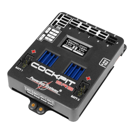
2. CONNECTIONS, CONTROLS The following illustrations show the essential sockets and controls: Door sequencer outputs Servo sockets OLED screen Battery input, Battery 1 and 2 Receiver inputs LEDs for power Switch buttons for ON signal Battery 1 and 2 LED for activation SET-Button Left: socket for Spektrum telemetry Connector for Jeti, Futaba, Mul-... - Page 5 3. FIRST STEPS, THE UNIT IN USE: In the following instructions we do not differentiate between the PowerBox Cockpit, Competition and Professional, since the method of programming the three units is absolutely identical. The only difference is that the Power- Box Cockpit includes the door sequencer function.
-
Page 6: Main Screen Display
This indicator is supplemented by the residual capacity display. - Residual battery capacity (Cockpit/Competition only): This display shows the momentary capacity value of the battery - again, as- suming that you have previously set the battery type correctly. This display... - Page 7 - Graphic indicator of battery charge state: This display is set to match the capacity you previously entered for the bat- teries connected to the backer. Assuming that the battery is of good quality, this means: if the bar only reaches the half-way point, then the battery is still half-full.
-
Page 8: Basic Settings
In the screenshot below you will see the default settings of the PowerBox Cockpit, Competition and Professional. If you wish to change them, this is the procedure:... - Page 9 - Switch both batteries on. - Press the SET button and hold it pressed in until the following display ap- pears: - Press button II until the cursor (hollow circular ring) lines up with Power Manager, then press the SET button. The following display now appears: If you wish to change one of the settings, use buttons I and II to move the cursor to the appropriate menu point, then press the SET button to select it (cursor changes to a solid disc).
- Page 10 Key to the individual menu points: - Chemistry: this is where you set the battery type. Three different types of battery are available: • Two-cell LiPo • Two-cell LiIon • Five-cell NiMH • Two-cell LiFe - Capacity: you can enter the nominal capacity of your batteries at this point. - Output voltage: you can select the output voltage to 7.4V or 5.9V CAUTION: if you intend to select the 7.4V output voltage, please ensure before you make the change that all the consumer units connected to...
- Page 11 4. SERVO MATCH FUNCTION The Servo-Match function provides the facility for adjusting the centre po- sition and end-points of the servos connected to the backer. If you have a model aircraft with more than one servo per control surface, this makes it possible to set up multiple servos to move to identical positions at identical times.
- Page 12 The following examples illustrate the correct procedure for the Servo-Match function: a) Fine-tuning multiple servos to operate on a single control surface; in this case the aileron of the right-hand wing. - Disconnect the linkages to the - as yet unmatched - servos, to avoid them being subjected to severe forces during the adjustment procedure.
- Page 13 b) Reversing an output when servos are installed in a “mirror-image” ar- rangement: in this case left and right landing flaps. - Disconnect the linkage to the left-hand landing flap, to avoid the servo being subjected to severe forces during the adjustment procedure. - Connect right landing flap to Output D, Servo 1 - First set up the right-hand landing flap servo in mechanical terms, using the transmitter;...
- Page 14 Select the SEQUENCER point at the main menu; this takes you to the follo- wing screen display: The SETUP ASSISTANT is a function in the Cockpit which has been included since software version V15; it makes the task of programming the actual door sequencer function considerably easier.
- Page 15 The on-screen arrows should now be located in front of UP/DOWN. If you find that your retract switch works in the wrong “sense” (direction), correct it by reversing that output at the transmitter. Press the SET button again to leave this function, and move the cursor to OK. The door sequencer’s method of working is determined in the following menu: The following sequences are available:...
- Page 16 Mode 3: Extend undercarriage: Open nosewheel doors extend nosewheel close nosewheel doors Open main wheel doors extend main undercarriage close main wheel doors Retract undercarriage: retract nosewheel close nosewheel doors Open nosewheel doors Open main wheel doors retract main undercarriage close main wheel doors Move the cursor to the appropriate mode, and press the SET button to con-...
- Page 17 The undercarriage should now retract. If not, hold button I pressed in until the valve is triggered, and the undercarriage retracts. Press the SET button to move on to the next stage of the procedure. Connect the nosewheel door servo to output 1. Press the SET button to clo- se the nosewheel door;...
- Page 18 Note: if you are only using one valve for all the wheel doors, you can by- pass the last five points by selecting OK. All the settings are now complete, and you will see one final safety query: Move your transmitter switch to the “gear down” position. It will now take a few moments for the Assistant to create the necessary tasks, and move the doors to the correct position without any fouling or jamming.
- Page 19 In spite of the vast scope of these facilities, the sequencer is simple and user-friendly to set up, as the screen and menu system guide you through the procedure. The sequencer software also features supplementary pro- gramming aids. Once you understand the principle, the system can easily be programmed without recourse to the manual.
- Page 20 Intelligent programming aid: If you wish to set up multiple tasks in order to move the wheel doors to several positions, it should be obvious that the new task’s initial positional value and start time are determined by the previous position and time for the servo concerned.
- Page 21 The positional values vary according to your linkages, and must be adjusted to suit your individual model. Clearly it is important to avoid your wheel doors jamming (striking their mechanical end-stops). The timing values shown here should also be set to suit your requirements. The task numbering does not need to coincide with the timed sequence;...
-
Page 22: Channel Lock When Undercarriage Is Retracted
6. CHANNEL LOCK WHEN UNDERCARRIAGE IS RETRACTED The PowerBox Cockpit’s door sequencer also features one last unique function: it is now possible to switch a channel off when the undercarriage is retracted. The purpose of this feature is to prevent the retracted nose- wheel moving inside the fuselage when the pilot gives a rudder command, as this may cause the mechanical system to jam. - Page 23 8. TELEMETRY The PowerBox Cockpit, Competition and Professional makes battery data available as telemetry information which can be exploited by various makes of radio control system. The unit supports the following makes of equip- ment, and other systems will gradually be introduced as updates become...
-
Page 24: Reset, Update, Save And Restore
9. RESET, UPDATE, SAVE AND RESTORE The PowerBox Cockpit, Competition and Professional offers numerous facilities for resetting individual ranges without affecting other settings. For example, it is possible to reset Door Sequencer without affecting the Servo Matching settings. All the Reset options can be found in the RESET/UPDATE menu: In the interests of safety, the software generates a confirmation query when you select one of the Reset options;... -
Page 25: Service Address
10. REGULATOR ERROR MESSAGE The PowerBox Cockpit, Competition and Professional constantly checks both voltage regulators independently of each other. If a fault should occur in one of these regulators, this warning will appear on the screen: There are three possible causes for this warning: - One or both regulators is generating insufficient output voltage or none at all. -
Page 26: Specification
2004/108/EG. The unit must not be connected to a mains PSU! The PowerBox Cockpit, Competition and Professional is intended exclusi- vely for use in modelling applications. It is prohibited to use it for any purpo- se other than in radio-controlled models. - Page 27 12. DIMENSIONS www.powerbox-systems.com...
-
Page 28: Set Contents
13. SET CONTENTS - PowerBox Cockpit / Competition / Professional - 8, 11 or 12 patch-leads - SensorSwitch - 4 rubber grommets and brass spacer sleeves, factory-fitted - 4 retaining screws - Operating instructions 14. SERVICE NOTE We make every effort to provide a good service to our customers, and have now established a Support Forum which covers all queries relating to our products. -
Page 29: Guarantee Conditions
15. GUARANTEE CONDITIONS We take the maintenance of the highest quality standards very seriously, and that is why PowerBox-Systems GmbH is currently the only RC electro- nics manufacturer which has been awarded certification to the DIN EN ISO 9001:2008 industrial norm. Our stringent quality management, which applies both to development and production, is the reason why we are able to grant a 36 month guarantee on our products, valid from the initial date of purchase. - Page 30 10/2017 PowerBox-Systems GmbH certificated according to DIN EN ISO 9001:2008 Ludwig-Auer-Straße 5 D-86609 Donauwoerth Germany +49-906-99 99 9-200 +49-906-22 45 9 www.powerbox-systems.com...
Need help?
Do you have a question about the cockpit and is the answer not in the manual?
Questions and answers