Advertisement
Quick Links
Advertisement

Subscribe to Our Youtube Channel
Related Manuals for PowerBox Systems PowerBox Source


Summary of Contents for PowerBox Systems PowerBox Source
- Page 1 Instruction Manual Powerbox Source...
- Page 2 We have managed to reduce the backer’s size by optimising the heat-sink design, and as a result the PowerBox Source is now also suitable for small models with high power requirements. This small energy package offers enormous performance reserves, and compares very well even with larger battery backer systems.
- Page 3 The PowerBox Source can be set to any of four different output voltages: 5.9 V – 7.4 V – 7.8 V and unregulated; in the latter case the battery voltage is passed through with minimal loss. The MPX inputs and outputs are fitted with retaining clips / lugs to prevent the connectors slipping out when subjected to severe vibration.
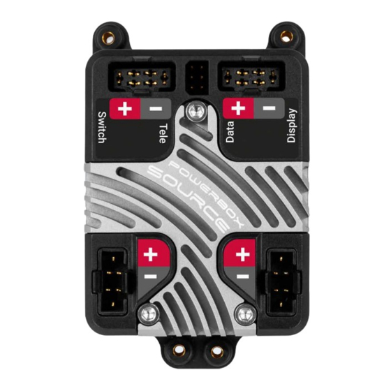
- Page 4 1. CONNECTIONS, CONTROLS Telemetrie socket USB socket Regulated output to receiver Display socket Switch socket Battery inputs PowerBox-Systems − World Leaders in RC Power Supply Systems...
- Page 5 2. INITIAL STEPS, OPERATING THE BACKER a) Connections First connect the receiver to the PowerBox Source using the patch leads supplied in the set. If your receiver features an MPX high-current input, use the MPX/MPX patch lead. If you have any vacant sockets, the second connection can be made by connecting an MPX/JR patch lead to a servo socket on the receiver.
- Page 6 - PowerBox ATOM/CORE By default the PowerBox Source is set up for the P²BUS. Connect the Tele out- put on the Source to the receiver’s P²BUS socket. The PowerBox can now be set up from the transmitter, and the telemetry data can be transferred.
- Page 7 LED lights up red. Now press buttons I and II in turn. Note: The PowerBox Source stores its last switched state. This means that a backer switched off using the Sensor Switch remains switched off. Once swit- ched on, the backer can only be switched off again using the Sensor Switch.
- Page 8 c) Settings There are several methods of entering settings, such as battery type and output voltage: - Using the Sensor Switch and the optional OLED screen (Order No. 4766) Locate the SET button on the switch, and hold it pressed in for about four to five seconds: this causes the menu to open.
- Page 9 Download the free PowerBox Terminal program from our website, and install it on your computer. Connect the USB Interface to the PC or laptop and connect the Uni connector to the PowerBox Source’s Data input. Select PowerBox Source, and follow the on-screen instructions.
- Page 10 Weight Sensor Switch 15 g Temperature range -30°C to +85°C 4. SET CONTENTS - PowerBox Source - SensorSwitch - 3 PowerPatch-leads (1x MPX / MPX and 2x MPX / JR) - 4 rubber grommets and brass spacers - 4 retaining screws - Operating instructions in English and German PowerBox-Systems −...
- Page 11 5. DIMENSIONS www.powerbox-systems.com...
- Page 12 They are guaranteed “Made in Germany”! That is why we are able to grant a 24 month guarantee on our PowerBox Source from the initial date of purchase. The guarantee covers proven material faults, which will be corrected by us at no charge to you.
- Page 13 For this reason we deny liability for loss, damage or costs which arise due to the use or operation of the PowerBox Source, or which are connected with such use in any way. Regardless of the legal arguments employed, our obligation to pay damages is limited to the invoice total of our products which were involved in the event, insofar as this is deemed legally permissible.
- Page 14 06/2023 PowerBox-Systems GmbH Ludwig-Auer-Straße 5 86609 Donauwörth Germany +49-906-99 99 9-200 www.powerbox-systems.com...
Need help?
Do you have a question about the PowerBox Source and is the answer not in the manual?
Questions and answers