Table of Contents
Advertisement
Quick Links
Advertisement
Table of Contents

Related Manuals for PowerBox Systems Champion SRS


Summary of Contents for PowerBox Systems Champion SRS
- Page 1 Instruction manual chAmpion Srs...
- Page 2 FEATURES Dear customer, we are delighted that you have decided to purchase the PowerBox Champion SRS power supply from our range. SRS: Seriell Receiver System provides the facility to use receivers with serial interface: PowerBox CORE, Spektrum DSM2 and DSMX, Jeti UDI, Futaba S-Bus, Multiplex M-Link, Graupner HoTT and JR DMSS We hope you have many hours of pleasure and great success with your PowerBox Champion SRS.
-
Page 3: Table Of Contents
CONTENTS 1. LAYOUT, CONNECTIONS servo sockets PowerBUS outputs 1. LAYOUT, CONNECTIONS ............................5 Battery sockets Spektrum TM1000 2. MAIN SCREEN, DATA LOGGER ..........................5 socket 3. INITIAL STEPS ................................7 a) Installation notes ................................7 USB Interface b) Switching the PowerBox on, the menu system ......................7 adapter socket c) Setting the receiving system to be used ........................7 d) Setting the battery type ..............................9... -
Page 4: Initial Steps
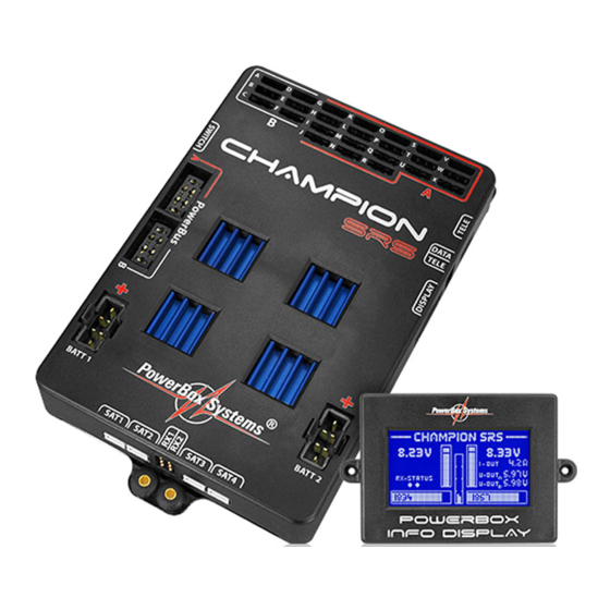
The Info Display does not need to be left permanently in the model, as the Champion SRS also functions without the screen connected. All you have to do is ensure that it can be plugged into the main unit... -
Page 5: Setting The Battery Type
V for regulator pair B. This feature makes it possible to connect a mixture of HV servos and normal servos to the PowerBox Champion SRS. The markings A (red) and B (black) on the case cover indicate which outputs are assigned to range A, and which to range B. - Page 6 This menu displays a graphic image of the outputs. You can use the cursor to move through the outputs in order By default, or after you have RESET the OUTPUT MAPPING, certain outputs are pre-defined in order to reduce to select the one you wish to assign. Pressing the SET button at a selected output highlights the FUNCTION field, the amount of set-up work the user is required to carry out.
-
Page 7: G) Using The Door Sequencer Assistant
OK, then press the SET button; the following display now appears: At this point the Champion SRS learns which switch is to be used: the unit automatically detects the approp- riate channel when you operate the transmitter switch you have assigned for the retractable undercarriage. -
Page 8: Servo-Match Function
All the settings are now complete, and you will see one final safety query: Connect the nosewheel door servo to output F. Press the SET button to close the nosewheel door; repeat the procedure in the next set-up screen to open the door. Move your transmitter switch to the “gear down”... -
Page 9: Channel Assignment, Input Side
- Use the SET button to select REVERSE SERVO. A tick appears after the function, and the left-hand landing flap To ensure accurate servo matching, the output to be adjusted must first be initialised. Leave the associated servo now operates in the correct direction. transmitter stick at centre. -
Page 10: Manual Door Sequenzer Installation
Procedure for setting up the Fail-Safe function: ac- We always recommend that you start the set-up procedure using the Setup Assistant. This incremental set-up cess the OUTPUT MAPPING menu and set the appro- aid creates the tasks required, automatically detects the retract switch channel, and assigns the door sequencer priate outputs to fail-safe as shown above. -
Page 11: Channel Lock When Undercarriage Is Retracted
8. CHANNEL LOCK WHEN UNDERCARRIAGE IS RETRACTED The PowerBox Champion SRS’s door sequencer also features one last unique function: it is now possible to switch a channel off when the undercarriage is retracted. The purpose of this feature is to prevent the retracted After a pause lasting 2.0 seconds at servo centre, the... -
Page 12: Telemetry
This is used to connect the TELE output on the PowerBox to the S-BUS 2 input of your receiver. In this way you can load updates into the Champion SRS to ensure that it constantly reflects the latest state of development. -
Page 13: Specification
12. SPECIFICATION Operating voltage: 4.0V - 9.0V Power supply: 2S LiPo/LiIon, 2S LiFePo, 2x 5S NiMH/NiCd Current drain: When operating: approx. 185 mA Idle current: approx. 30µA Output voltage: 5.9V and / or 7.4V stabilised Current load: Peak 4 x 20A Dropout voltage: 0.3V Servo signal resolution:... -
Page 14: Set Contents
They are guaranteed “Made in Germany”! That is why we are able to grant a 36 month guarantee on our PowerBox Champion SRS from the initial date of purchase. The guarantee covers proven material faults, which will be corrected by us at no charge to you. As a precautionary measure, we are obliged to point out that we reserve the right to replace the unit if we deem the repair to be economically unviable. - Page 15 01/2019 -Systems GmbH PowerBox certified according to DIN EN ISO 9001 Ludwig-Auer-Straße 5 D-86609 Donauwoerth Germany +49-906-99 99 9-200 +49-906-99 99 9-209 www. -systems.com powerbox...
Need help?
Do you have a question about the Champion SRS and is the answer not in the manual?
Questions and answers