GE 750 Manual
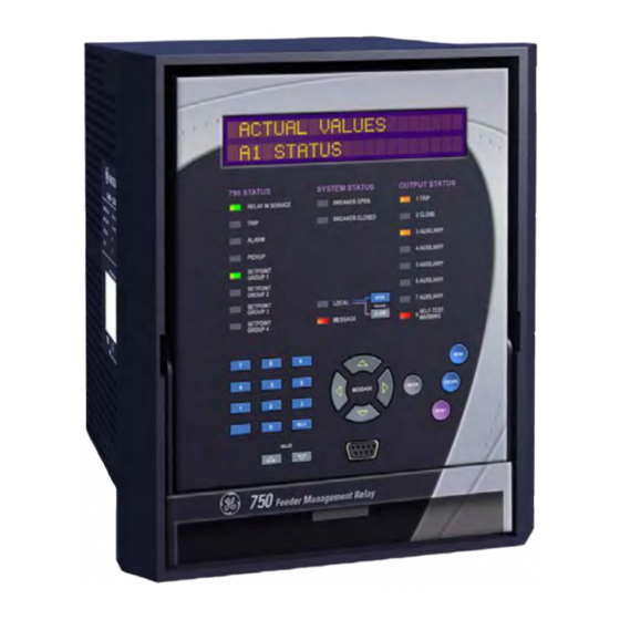
Feeder management relay
Hide thumbs
Also See for 750:
- Instruction manual (504 pages) ,
- Quick reference manual (58 pages) ,
- Clinical reference manual (50 pages)

Related Manuals for GE 750


Summary of Contents for GE 750
- Page 1 Grid Solutions 750/760 Feeder Management Relay Note COMMUNICATIONS GUIDE Software Revision: 7.4x GE Multilin Part Number: 1601-0229-AB GE Publication Code: GEK-106473K *1601-0229-AB*...
- Page 2 The contents of this manual are the property of GE Multilin Inc. This documentation is furnished on license and may not be reproduced in whole or in part without the permission of GE Multilin Inc. The content of this manual is for informational use only and is subject to change without notice.
- Page 3 Website: http://www.gegridsolutions.com/multilin Warranty For products shipped as of 1 October 2013, GE warrants most of its GE manufactured products for 10 years. For warranty details including any limitations and disclaimers, see our Terms and Conditions at https://www.gegridsolutions.com/multilin/warranty.htm For products shipped before 1 October 2013, the standard 24-month warranty applies.
-
Page 5: Table Of Contents
6.DNP POINT LISTS Binary Input / Binary Input Change ..................6 - 1 Binary / Control Relay Output....................6 - 3 Analog Input / Analog Input Change ..................6 - 5 750/760 FEEDER MANAGEMENT RELAY – COMMUNICATIONS GUIDE TOC - V... - Page 6 TOC - VI 750/760 FEEDER MANAGEMENT RELAY – COMMUNICATIONS GUIDE...
-
Page 7: Overviewprotocols
AEG Modicon Modbus protocol or the Harris Distributed Network Protocol (DNP), Version 3.0. Following are some general notes: • The 750/760 relay always act as slave devices meaning that they never initiate communications; they only listen and respond to requests issued by a master computer. -
Page 8: Physical Layer
The master device in any system must know the address of the slave device with which it is to communicate. The 750/760 will not act on a request from a master if the address in the request does not match the relay's slave address (unless the address is the broadcast address –... -
Page 9: Description
• Slave Address: This is the address of the slave device intended to receive the packet sent by the master and perform the desired action. Each slave device on a 750/760 FEEDER MANAGEMENT RELAY – COMMUNICATIONS GUIDE 2 - 1... -
Page 10: Crc-16 Algorithm
Relays on page 3-7 for an example of broadcast mode. • Function Code: This is one of the supported functions codes of the 750/760 which tells the slave what action to perform. See Supported Modbus Function Codes on page 3-1 for complete details. -
Page 11: Message Timing
9. i + 1 --> i 10. Is i = N? If No: go to 3; if Yes: continue. 11. A --> CRC GE Multilin will provide a C programming language implementation of this algorithm upon request. Message Timing Communication message synchronization is maintained by timing constraints. The receiving device must measure the time between the reception of characters. - Page 12 MESSAGE TIMING CHAPTER 2: MODBUS PROTOCOL 2 - 4 750/760 FEEDER MANAGEMENT RELAY – COMMUNICATIONS GUIDE...
-
Page 13: Supported Modbus Function Codes
Supported Modbus Function Codes Modbus officially defines function codes from 1 to 127 though only a small subset is generally needed. The 750/760 relays support some of these functions, as summarized below. Subsequent sections describe each function code in detail. -
Page 14: Function Code 01H/02H: Read Binary Status
These function codes allow the master to read one or more consecutive binary status bits from an 750/760. The status bits are packed into bytes with the first addressed bit occupying the least significant bit position of the first returned byte. Enough bytes are returned to contain all requested status bits. -
Page 15: Function Code 05H: Execute Operation
Since some PLC implementations of Modbus only support one of function codes 03h and 04h, the 750/760 interpretation allows either function code to be used for reading one or more consecutive data registers. The data starting address will determine the type of data being read. - Page 16 Reset Ar Count Data Resets the Autoreclose Count by setting the to zero. AR SHOT COUNT 0011h Reset Ar Rate Data Resets the Autoreclose Shot Rate by setting to zero. AR SHOT RATE 3 - 4 750/760 FEEDER MANAGEMENT RELAY – COMMUNICATIONS GUIDE...
-
Page 17: Function Code 06H: Store Single Setpoint
This function code allows the master to modify the contents of a one or more consecutive setpoint registers in a 750/760. Setpoint registers are 16 bit (two byte) values transmitted high-order byte first. The maximum number of setpoint registers that can be stored in a single packet is 60. -
Page 18: Exception Responses
These errors result in an exception response from the slave. The GE Multilin 750/760 implements the error codes listed below. The slave detecting one of these errors sends a response packet to the master with the high-order bit of the function code set to 1. -
Page 19: Clock Synchronization Of Multiple Relays
The message was received without error, but the request could not be Nak - Negative performed, because this version of the 750/760 does not have the Acknowledge requested operation available. * Some Modbus implementations may not support these exception responses... - Page 20 Operation Code 00 04 set time Code Value FF 00 perform operation CRC (Low, High) CC 2A computed CRC error code Slave Response Bytes Example Description No response from slave. 3 - 8 750/760 FEEDER MANAGEMENT RELAY – COMMUNICATIONS GUIDE...
-
Page 21: Reading The Event Recorder
The system now writes the value 26 to the selector and then reads the data for event number 750/760 FEEDER MANAGEMENT RELAY – COMMUNICATIONS GUIDE 4 - 1... -
Page 22: Reading Trace Memory
Data for Trace Memory number 3 can now be read from the ‘Trace Memory Information’ registers at addresses 2111h to 2119h. These registers include a trigger cause (see the previous section for a description of the data format), a trigger time and date 4 - 2 750/760 FEEDER MANAGEMENT RELAY – COMMUNICATIONS GUIDE... - Page 23 Write TMSS to Trace Memory Sample Selector. Read 64 samples from Trace Memory Samples and store to SCADA memory. Increment TMSS by 64. 10. If TMSS < Total Number of Samples then go to Step 5. 750/760 FEEDER MANAGEMENT RELAY – COMMUNICATIONS GUIDE 4 - 3...
-
Page 24: Reading The Data Logger
Accessing Data via the User Map The 750/760 has a powerful feature, called the User Map, which allows a computer to read up to 120 non-consecutive data registers (setpoints or actual values) by using one Modbus packet. -
Page 25: Memory Map Organization
0105h Memory Map Organization The 750/760 Memory Map describes all the data registers that can be accessed via serial communications. The Memory Map address range is grouped into several categories as outlined in the following table. All memory map locations are two byte (16 bit) values. The remaining pages of this chapter list all locations of the Memory Map. -
Page 26: Memory Map
3000h to 3FFFh Reserved for future use. Factory Service 4000h to FFFFh Reserved. Data Memory Map The 750/760 memory map is shown in the following table. Table 3: Modbus Memory Map (Sheet 1 of 40) ADDR DESCRIPTION RANGE UNITS TYPE... - Page 27 User Map Value #28 1 2 3 4 5 6 7 8 9 10 11 12 13 For explanation of Table footnotes, see the Memory Map Notes at the end of this table. 750/760 FEEDER MANAGEMENT RELAY – COMMUNICATIONS GUIDE 4 - 7...
- Page 28 User Map Value #81 1 2 3 4 5 6 7 8 9 10 11 12 13 For explanation of Table footnotes, see the Memory Map Notes at the end of this table. 4 - 8 750/760 FEEDER MANAGEMENT RELAY – COMMUNICATIONS GUIDE...
- Page 29 0000 to FFFF 1 2 3 4 5 6 7 8 9 10 11 12 13 For explanation of Table footnotes, see the Memory Map Notes at the end of this table. 750/760 FEEDER MANAGEMENT RELAY – COMMUNICATIONS GUIDE 4 - 9...
- Page 30 0000 to FFFF 1 2 3 4 5 6 7 8 9 10 11 12 13 For explanation of Table footnotes, see the Memory Map Notes at the end of this table. 4 - 10 750/760 FEEDER MANAGEMENT RELAY – COMMUNICATIONS GUIDE...
- Page 31 0000 to FFFF 1 2 3 4 5 6 7 8 9 10 11 12 13 For explanation of Table footnotes, see the Memory Map Notes at the end of this table. 750/760 FEEDER MANAGEMENT RELAY – COMMUNICATIONS GUIDE 4 - 11...
- Page 32 Communications) 1 2 3 4 5 6 7 8 9 10 11 12 13 For explanation of Table footnotes, see the Memory Map Notes at the end of this table. 4 - 12 750/760 FEEDER MANAGEMENT RELAY – COMMUNICATIONS GUIDE...
- Page 33 0 to 65535 1 2 3 4 5 6 7 8 9 10 11 12 13 For explanation of Table footnotes, see the Memory Map Notes at the end of this table. 750/760 FEEDER MANAGEMENT RELAY – COMMUNICATIONS GUIDE 4 - 13...
- Page 34 0 to 65535 1 2 3 4 5 6 7 8 9 10 11 12 13 For explanation of Table footnotes, see the Memory Map Notes at the end of this table. 4 - 14 750/760 FEEDER MANAGEMENT RELAY – COMMUNICATIONS GUIDE...
- Page 35 Date of Fault 0 (2 words) 1 2 3 4 5 6 7 8 9 10 11 12 13 For explanation of Table footnotes, see the Memory Map Notes at the end of this table. 750/760 FEEDER MANAGEMENT RELAY – COMMUNICATIONS GUIDE 4 - 15...
- Page 36 1 2 3 4 5 6 7 8 9 10 11 12 13 For explanation of Table footnotes, see the Memory Map Notes at the end of this table. 4 - 16 750/760 FEEDER MANAGEMENT RELAY – COMMUNICATIONS GUIDE...
- Page 37 Cold Load Pickup Blocking 1 2 3 4 5 6 7 8 9 10 11 12 13 For explanation of Table footnotes, see the Memory Map Notes at the end of this table. 750/760 FEEDER MANAGEMENT RELAY – COMMUNICATIONS GUIDE 4 - 17...
- Page 38 0640 1 2 3 4 5 6 7 8 9 10 11 12 13 For explanation of Table footnotes, see the Memory Map Notes at the end of this table. 4 - 18 750/760 FEEDER MANAGEMENT RELAY – COMMUNICATIONS GUIDE...
- Page 39 Default Message #3 1 2 3 4 5 6 7 8 9 10 11 12 13 For explanation of Table footnotes, see the Memory Map Notes at the end of this table. 750/760 FEEDER MANAGEMENT RELAY – COMMUNICATIONS GUIDE 4 - 19...
- Page 40 16 x 256 1 2 3 4 5 6 7 8 9 10 11 12 13 For explanation of Table footnotes, see the Memory Map Notes at the end of this table. 4 - 20 750/760 FEEDER MANAGEMENT RELAY – COMMUNICATIONS GUIDE...
- Page 41 114C 1 2 3 4 5 6 7 8 9 10 11 12 13 For explanation of Table footnotes, see the Memory Map Notes at the end of this table. 750/760 FEEDER MANAGEMENT RELAY – COMMUNICATIONS GUIDE 4 - 21...
- Page 42 USER INPUT F (read/write setpoints) 1 2 3 4 5 6 7 8 9 10 11 12 13 For explanation of Table footnotes, see the Memory Map Notes at the end of this table. 4 - 22 750/760 FEEDER MANAGEMENT RELAY – COMMUNICATIONS GUIDE...
- Page 43 Disabled 1 2 3 4 5 6 7 8 9 10 11 12 13 For explanation of Table footnotes, see the Memory Map Notes at the end of this table. 750/760 FEEDER MANAGEMENT RELAY – COMMUNICATIONS GUIDE 4 - 23...
- Page 44 Self-resetting 1 2 3 4 5 6 7 8 9 10 11 12 13 For explanation of Table footnotes, see the Memory Map Notes at the end of this table. 4 - 24 750/760 FEEDER MANAGEMENT RELAY – COMMUNICATIONS GUIDE...
- Page 45 13E9 1 2 3 4 5 6 7 8 9 10 11 12 13 For explanation of Table footnotes, see the Memory Map Notes at the end of this table. 750/760 FEEDER MANAGEMENT RELAY – COMMUNICATIONS GUIDE 4 - 25...
- Page 46 0 ms 1 2 3 4 5 6 7 8 9 10 11 12 13 For explanation of Table footnotes, see the Memory Map Notes at the end of this table. 4 - 26 750/760 FEEDER MANAGEMENT RELAY – COMMUNICATIONS GUIDE...
- Page 47 0 ms 1 2 3 4 5 6 7 8 9 10 11 12 13 For explanation of Table footnotes, see the Memory Map Notes at the end of this table. 750/760 FEEDER MANAGEMENT RELAY – COMMUNICATIONS GUIDE 4 - 27...
- Page 48 0 ms 1 2 3 4 5 6 7 8 9 10 11 12 13 For explanation of Table footnotes, see the Memory Map Notes at the end of this table. 4 - 28 750/760 FEEDER MANAGEMENT RELAY – COMMUNICATIONS GUIDE...
- Page 49 150D 1 2 3 4 5 6 7 8 9 10 11 12 13 For explanation of Table footnotes, see the Memory Map Notes at the end of this table. 750/760 FEEDER MANAGEMENT RELAY – COMMUNICATIONS GUIDE 4 - 29...
- Page 50 1633 1 2 3 4 5 6 7 8 9 10 11 12 13 For explanation of Table footnotes, see the Memory Map Notes at the end of this table. 4 - 30 750/760 FEEDER MANAGEMENT RELAY – COMMUNICATIONS GUIDE...
- Page 51 1722 1 2 3 4 5 6 7 8 9 10 11 12 13 For explanation of Table footnotes, see the Memory Map Notes at the end of this table. 750/760 FEEDER MANAGEMENT RELAY – COMMUNICATIONS GUIDE 4 - 31...
- Page 52 Disabled 1 2 3 4 5 6 7 8 9 10 11 12 13 For explanation of Table footnotes, see the Memory Map Notes at the end of this table. 4 - 32 750/760 FEEDER MANAGEMENT RELAY – COMMUNICATIONS GUIDE...
- Page 53 17C2 1 2 3 4 5 6 7 8 9 10 11 12 13 For explanation of Table footnotes, see the Memory Map Notes at the end of this table. 750/760 FEEDER MANAGEMENT RELAY – COMMUNICATIONS GUIDE 4 - 33...
- Page 54 20 min. 1 2 3 4 5 6 7 8 9 10 11 12 13 For explanation of Table footnotes, see the Memory Map Notes at the end of this table. 4 - 34 750/760 FEEDER MANAGEMENT RELAY – COMMUNICATIONS GUIDE...
- Page 55 100 s 1 2 3 4 5 6 7 8 9 10 11 12 13 For explanation of Table footnotes, see the Memory Map Notes at the end of this table. 750/760 FEEDER MANAGEMENT RELAY – COMMUNICATIONS GUIDE 4 - 35...
- Page 56 None 1 2 3 4 5 6 7 8 9 10 11 12 13 For explanation of Table footnotes, see the Memory Map Notes at the end of this table. 4 - 36 750/760 FEEDER MANAGEMENT RELAY – COMMUNICATIONS GUIDE...
- Page 57 Disabled 1 2 3 4 5 6 7 8 9 10 11 12 13 For explanation of Table footnotes, see the Memory Map Notes at the end of this table. 750/760 FEEDER MANAGEMENT RELAY – COMMUNICATIONS GUIDE 4 - 37...
- Page 58 Disabled 1 2 3 4 5 6 7 8 9 10 11 12 13 For explanation of Table footnotes, see the Memory Map Notes at the end of this table. 4 - 38 750/760 FEEDER MANAGEMENT RELAY – COMMUNICATIONS GUIDE...
- Page 59 1B73 1 2 3 4 5 6 7 8 9 10 11 12 13 For explanation of Table footnotes, see the Memory Map Notes at the end of this table. 750/760 FEEDER MANAGEMENT RELAY – COMMUNICATIONS GUIDE 4 - 39...
- Page 60 1BD2 1 2 3 4 5 6 7 8 9 10 11 12 13 For explanation of Table footnotes, see the Memory Map Notes at the end of this table. 4 - 40 750/760 FEEDER MANAGEMENT RELAY – COMMUNICATIONS GUIDE...
- Page 61 0 to 65535 1 2 3 4 5 6 7 8 9 10 11 12 13 For explanation of Table footnotes, see the Memory Map Notes at the end of this table. 750/760 FEEDER MANAGEMENT RELAY – COMMUNICATIONS GUIDE 4 - 41...
- Page 62 Trace Memory Sample TMSS+7 1 2 3 4 5 6 7 8 9 10 11 12 13 For explanation of Table footnotes, see the Memory Map Notes at the end of this table. 4 - 42 750/760 FEEDER MANAGEMENT RELAY – COMMUNICATIONS GUIDE...
- Page 63 Trace Memory Sample TMSS+60 1 2 3 4 5 6 7 8 9 10 11 12 13 For explanation of Table footnotes, see the Memory Map Notes at the end of this table. 750/760 FEEDER MANAGEMENT RELAY – COMMUNICATIONS GUIDE 4 - 43...
- Page 64 Data Logger Sample DLSS+36 1 2 3 4 5 6 7 8 9 10 11 12 13 For explanation of Table footnotes, see the Memory Map Notes at the end of this table. 4 - 44 750/760 FEEDER MANAGEMENT RELAY – COMMUNICATIONS GUIDE...
- Page 65 These registers are new or have changed for version 3.20 These registers are new for version 3.30 These registers are new or have changed for version 3.40 MOD 010 These registers are new or have changed for version 3.60 750/760 FEEDER MANAGEMENT RELAY – COMMUNICATIONS GUIDE 4 - 45...
-
Page 66: Data Formats
Low order word of long value stored in 2nd 16 bits Example: -1234.56 stored as -123456 1 2 3 4 5 6 7 8 9 10 11 12 13 For explanation of footnotes, see notes of end of Table. 4 - 46 750/760 FEEDER MANAGEMENT RELAY – COMMUNICATIONS GUIDE... - Page 67 Clear Energy Use Data Clear Max Demand Data 1 2 3 4 5 6 7 8 9 10 11 12 13 For explanation of footnotes, see notes of end of Table. 750/760 FEEDER MANAGEMENT RELAY – COMMUNICATIONS GUIDE 4 - 47...
- Page 68 NOTE: If the date has never been set then all 32 bits will be 1. 1 2 3 4 5 6 7 8 9 10 11 12 13 For explanation of footnotes, see notes of end of Table. 4 - 48 750/760 FEEDER MANAGEMENT RELAY – COMMUNICATIONS GUIDE...
- Page 69 General Event Type 00FFh Event Cause (last 8 bits) 1 2 3 4 5 6 7 8 9 10 11 12 13 For explanation of footnotes, see notes of end of Table. 750/760 FEEDER MANAGEMENT RELAY – COMMUNICATIONS GUIDE 4 - 49...
- Page 70 Phase Instantaneous Overcurrent 1 Phase Instantaneous Overcurrent 2 1 2 3 4 5 6 7 8 9 10 11 12 13 For explanation of footnotes, see notes of end of Table. 4 - 50 750/760 FEEDER MANAGEMENT RELAY – COMMUNICATIONS GUIDE...
- Page 71 Negative Sequence Time Overcurrent Negative Sequence Overvoltage Undervoltage Restoration 1 2 3 4 5 6 7 8 9 10 11 12 13 For explanation of footnotes, see notes of end of Table. 750/760 FEEDER MANAGEMENT RELAY – COMMUNICATIONS GUIDE 4 - 51...
- Page 72 Setpoint Group 4 User Input A User Input B 1 2 3 4 5 6 7 8 9 10 11 12 13 For explanation of footnotes, see notes of end of Table. 4 - 52 750/760 FEEDER MANAGEMENT RELAY – COMMUNICATIONS GUIDE...
- Page 73 Cancel Reclosure Block Reclosure Trigger Trace Memory 1 2 3 4 5 6 7 8 9 10 11 12 13 For explanation of footnotes, see notes of end of Table. 750/760 FEEDER MANAGEMENT RELAY – COMMUNICATIONS GUIDE 4 - 53...
- Page 74 Event Cause (last 8 bits) Event Rate High EEPROM Usage High 1 2 3 4 5 6 7 8 9 10 11 12 13 For explanation of footnotes, see notes of end of Table. 4 - 54 750/760 FEEDER MANAGEMENT RELAY – COMMUNICATIONS GUIDE...
- Page 75 Energized Relay Output Type Self-Resetting Latched Pulsed 1 2 3 4 5 6 7 8 9 10 11 12 13 For explanation of footnotes, see notes of end of Table. 750/760 FEEDER MANAGEMENT RELAY – COMMUNICATIONS GUIDE 4 - 55...
- Page 76 Current/Voltage Phases Any One Any Two All Three 1 2 3 4 5 6 7 8 9 10 11 12 13 For explanation of footnotes, see notes of end of Table. 4 - 56 750/760 FEEDER MANAGEMENT RELAY – COMMUNICATIONS GUIDE...
- Page 77 Phase C (0=Phase C is not picked up/operating, 1= Phase C is picked up/operating) 1 2 3 4 5 6 7 8 9 10 11 12 13 For explanation of footnotes, see notes of end of Table. 750/760 FEEDER MANAGEMENT RELAY – COMMUNICATIONS GUIDE 4 - 57...
- Page 78 LED #8 (Bottom) (0 = Off, 1 = On) 1 2 3 4 5 6 7 8 9 10 11 12 13 For explanation of footnotes, see notes of end of Table. 4 - 58 750/760 FEEDER MANAGEMENT RELAY – COMMUNICATIONS GUIDE...
- Page 79 Prototype Unit (0 = OK, 1 = Installed) 1 2 3 4 5 6 7 8 9 10 11 12 13 For explanation of footnotes, see notes of end of Table. 750/760 FEEDER MANAGEMENT RELAY – COMMUNICATIONS GUIDE 4 - 59...
- Page 80 Unsigned Value, 3 Decimal Places Example: 1.234 stored as 1234 1 2 3 4 5 6 7 8 9 10 11 12 13 For explanation of footnotes, see notes of end of Table. 4 - 60 750/760 FEEDER MANAGEMENT RELAY – COMMUNICATIONS GUIDE...
- Page 81 Phase B-N Voltage Phase C-N Voltage Average Phase Voltage 1 2 3 4 5 6 7 8 9 10 11 12 13 For explanation of footnotes, see notes of end of Table. 750/760 FEEDER MANAGEMENT RELAY – COMMUNICATIONS GUIDE 4 - 61...
- Page 82 Frequency Decay Rate Polarizing Current Phase A Current Angle Phase B Current Angle Phase C Current Angle Neutral Current Angle Ground Current Angle Polarizing Current Angle A-N Voltage Angle B-N Voltage Angle 4 - 62 750/760 FEEDER MANAGEMENT RELAY – COMMUNICATIONS GUIDE...
- Page 83 4 x 1024 8 x 512 16 x 256 1 2 3 4 5 6 7 8 9 10 11 12 13 For explanation of footnotes, see notes of end of Table. 750/760 FEEDER MANAGEMENT RELAY – COMMUNICATIONS GUIDE 4 - 63...
- Page 84 Bus Transfer Logic Schemes Scheme 1 Scheme 2 1 2 3 4 5 6 7 8 9 10 11 12 13 For explanation of footnotes, see notes of end of Table. 4 - 64 750/760 FEEDER MANAGEMENT RELAY – COMMUNICATIONS GUIDE...
-
Page 85: Data Formats Notes
2013 Time of 02E2 F22 first 16 bits 0F3B Hour = 0F 3:59 pm last trip Minute = 3B 02E3 F22 second 16 bits 87CC Milliseconds = 87CC 34.764 seconds 750/760 FEEDER MANAGEMENT RELAY – COMMUNICATIONS GUIDE 4 - 65... - Page 86 13. The ADDR 000C register, Installed Option: Harsh Environment, has changed for version 7.43 in relays manufactured after February 2014. With earlier firmware or manufacture date, ADDR 000C always reads as value 0. 4 - 66 750/760 FEEDER MANAGEMENT RELAY – COMMUNICATIONS GUIDE...
- Page 87 (octets): Transmitted: 292 Transmitted: 2048 Received: 292 Received: 2048 Maximum Data Link Re-tries: Maximum Application Layer Re-tries: None Ë None Ë Fixed Ë Configurable Ë Configurable (note 1) 750/760 FEEDER MANAGEMENT RELAY – COMMUNICATIONS GUIDE 5 - 1...
- Page 88 Sends Static Data in Unsolicited Ë Responses: Configurable Ë Never Ë Only certain objects Ë When Device Restarts Ë Sometimes Ë When Status Flags Change Ë ENABLE/DISABLE UNSOLICITED Ë Function codes supported 5 - 2 750/760 FEEDER MANAGEMENT RELAY – COMMUNICATIONS GUIDE...
-
Page 89: Dnp Implementation
32-Bit Analog Input Without Flag 00, 01, 06 00, 01 16-Bit Analog Input Without Flag 00, 01, 06 00, 01 1, 2, 3, 4, 5, 6: see the IMPLEMENATION TABLE NOTES above. 750/760 FEEDER MANAGEMENT RELAY – COMMUNICATIONS GUIDE 5 - 3... - Page 90 Object Description Default Variation Binary Input - Single Bit Binary Input Change With Time Binary Output Status 16-Bit Analog Input Without Flag 16-Bit Analog Input Change Without Time 5 - 4 750/760 FEEDER MANAGEMENT RELAY – COMMUNICATIONS GUIDE...
-
Page 91: Binary Input / Binary Input Change
Class 1 Breaker Is Closed Class 1 Class 1 Reclosure Enabled Class 1 Reclosure Disabled Class 1 Reclosure In Progress Class 1 Reclosure Locked Out Local Mode Active Class 1 750/760 FEEDER MANAGEMENT RELAY – COMMUNICATIONS GUIDE 6 - 1... - Page 92 Any detected change in the state of any point will cause the generation of an event object. An event object will be generated as a result of any change in any point. 6 - 2 750/760 FEEDER MANAGEMENT RELAY – COMMUNICATIONS GUIDE...
-
Page 93: Binary / Control Relay Output
Virtual Input 18 Virtual Input 19 Virtual Input 20 Breaker Control The following restrictions should be observed when using object 12 to control the points listed in the above table. 750/760 FEEDER MANAGEMENT RELAY – COMMUNICATIONS GUIDE 6 - 3... - Page 94 When using object 10 to read the status of a Binary Output, a read of points 0 through 2 and 23 will always return zero. For other points, the current state of the corresponding Virtual Input will be returned. 6 - 4 750/760 FEEDER MANAGEMENT RELAY – COMMUNICATIONS GUIDE...
-
Page 95: Analog Input / Analog Input Change
Neutral Directional Is Reverse Class 1 Manual Close Blocking Class 1 Cold Load Pickup Blocking Class 1 Bus Undervoltage 1 Class 1 Bus Undervoltage 2 Class 1 Line Undervoltage 1 Class 1 750/760 FEEDER MANAGEMENT RELAY – COMMUNICATIONS GUIDE 6 - 5... - Page 96 Breaker Operation Failure Class 1 Trip Coil Monitor Class 1 Close Coil Monitor Class 1 User Input A Class 1 User Input B Class 1 User Input C Class 1 6 - 6 750/760 FEEDER MANAGEMENT RELAY – COMMUNICATIONS GUIDE...
- Page 97 Class 2 Phase B-Phase C RMS Voltage (see Note 3) Class 2 Phase C-Phase A RMS Voltage (see Note 3) Class 2 Sensitive Ground Current (see Note 3) Class 2 750/760 FEEDER MANAGEMENT RELAY – COMMUNICATIONS GUIDE 6 - 7...
- Page 98 Date Of Fault 0 (Upper 16 Bits - See Note 1) Class 3 Date Of Fault 0 (Lower 16 Bits - See Note 1) Class 3 Time Of Fault 0 (Upper 16 Bits - See Note 1) Class 3 6 - 8 750/760 FEEDER MANAGEMENT RELAY – COMMUNICATIONS GUIDE...
- Page 99 Date Of Fault 4 (Lower 16 Bits - See Note 1) Time Of Fault 4 (Upper 16 Bits - See Note 1) Time Of Fault 4 (Lower 16 Bits - See Note 1) 750/760 FEEDER MANAGEMENT RELAY – COMMUNICATIONS GUIDE 6 - 9...
- Page 100 Date Of Fault 8 (Lower 16 Bits - See Note 1) Time Of Fault 8 (Upper 16 Bits - See Note 1) Time Of Fault 8 (Lower 16 Bits - See Note 1) Type Of Fault 8 6 - 10 750/760 FEEDER MANAGEMENT RELAY – COMMUNICATIONS GUIDE...
- Page 101 User Input T Class 1 Autoreclose Rate Supervision Class 1 Restricted Earth Fault Class 1 Auto Ranging Power / Energy Multiplier Class 2 Neutral Voltage (see Note 3) Class 2 750/760 FEEDER MANAGEMENT RELAY – COMMUNICATIONS GUIDE 6 - 11...
- Page 102 Modbus). Refer to Accessing Data via the User Map on page 4-4 for more information. Please note that changes in User Map Values never generate event objects. 6 - 12 750/760 FEEDER MANAGEMENT RELAY – COMMUNICATIONS GUIDE...