Table of Contents
Advertisement
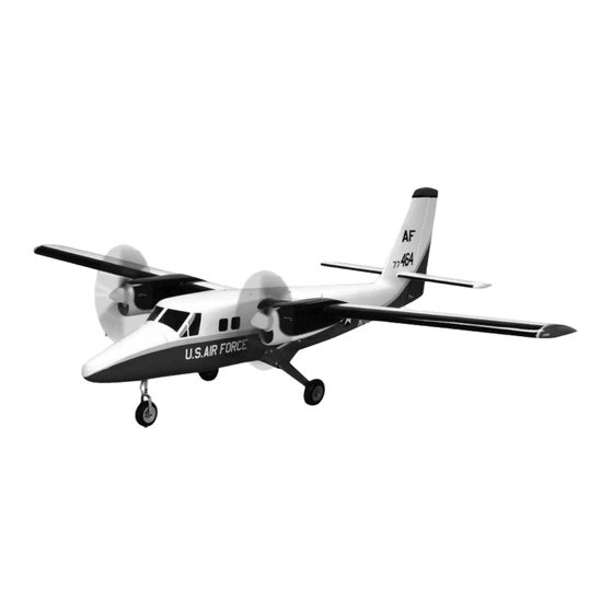
Twin Otter ARF
Assembly Manual
Wingspan..................................................................................... 82.0 in (2080mm)
Length.......................................................................................... 65.0 in (1651mm)
Wing Area.......................................................................... 738 sq in (47.61 sq dm)
Weight........................................................................ 11 1/2–12 1/4 lb (5.2–6.0 kg)
Radio.............................................................................. 7-channel w/8–10 servos
Engine................................................................................. 36 2-stroke; Power 25
Specifications
Advertisement
Table of Contents

Related Manuals for Hangar 9 Twin Otter ARF


Summary of Contents for Hangar 9 Twin Otter ARF
- Page 1 Twin Otter ARF Assembly Manual Specifications Wingspan..................82.0 in (2080mm) Length..................65.0 in (1651mm) Wing Area................738 sq in (47.61 sq dm) Weight................ 11 1/2–12 1/4 lb (5.2–6.0 kg) Radio................7-channel w/8–10 servos Engine................. 36 2-stroke; Power 25...
-
Page 2: Table Of Contents
Build and Flying Notes..........44 HAN461009 Right Wing HAN461017 Glow Mounting Pack Warranty Information..........45 HAN461010 Struts HAN461018 Main Hardware Pack Compliance Information for the European Union..46 HAN461011 Nose Gear Assembly HAN461019 Fuel Tanks 2010 AMA Safety Code..........47 Twin Otter ARF Assembly Manual... -
Page 3: Included Hardware
2-56 x 10-in steel pushrods throttles 2-56 x 7-in steel pushrod nose gear steering Rudder Cable Bag Rudder cable 82 inch rudder cables Copper crimps Wire cable ends EZ links rudder servo Twin Otter ARF Assembly Manual... -
Page 4: Introduction
Introduction Radio Equipment Requirements - Required Tools and Equipment 7-Channel Receiver Hangar 9’s latest introduction, the Twin Otter is a Drill motor Pin vise scale model of the UV-18 ‘Twin Otter’, the military Low-tack tape Needle-nose pliers The following items are required when installing the version of the DeHavilland DHC-6. -
Page 5: Using The Manual
During the course of building your Twin Otter we assembly easier to understand, and to provide breaks enjoyment from your Hangar 9 products. We strongly suggest you use a soft base on the building between each major section. In addition, check boxes encourage you to register your product using the surface. -
Page 6: Elevator Servo Installation
Note that the bushings it 1/4 inch from the aft end of the hatch. are installed from the bottom of the servo. Twin Otter ARF Assembly Manual... - Page 7 CA to each of the holes to strengthen the wood. protrudes into the servo bay in the stabilizer. Be Allow the CA to cure without using accelerator. careful not to puncture the upper skin. Twin Otter ARF Assembly Manual...
- Page 8 Use your radio to center the elevator servo then use a Feed the elevator servo lead through the forward felt-tipped pen to mark the pushrod at the servo arm. holes in the ribs to the stabilizer root and set the hatch in place. Twin Otter ARF Assembly Manual...
-
Page 9: Aileron Servo Installation
Slide the bent aileron servos. Note that the bushings are installed end through the outer servo arm hole and secure it from the bottom of the mounting lugs. with a snap keeper. Twin Otter ARF Assembly Manual... - Page 10 10 x 11 x 20mm servo mounting blocks in place. Prepare a second servo for the right-hand aileron with spaced in the long direction of the hatch. There will be the arm facing the opposite direction. approximately a 3/16 inch gap at each end. Twin Otter ARF Assembly Manual...
- Page 11 Hint: Apply a very small drop of thin CA to the knot to There is a pull string provided to draw the aileron prevent it coming loose. servo lead through the wing. Tape the string to the servo extension and pull it through to the wing root. Twin Otter ARF Assembly Manual...
- Page 12 Slide the bent mark the pushrod at the servo arm. portion of the pushrod through the outer hole of the servo arm and secure it with a snap keeper. Twin Otter ARF Assembly Manual...
-
Page 13: Flap Servo Installation
Note that the bushings are installed from length of 9/32 inch (7mm). the bottom of the mounting lugs. Step 22 Repeat steps 4 through 20 to install the servo in the right-hand wing panel. Twin Otter ARF Assembly Manual... - Page 14 Allow the CA to cure without of the servo 1/8 inch above the outboard edge of the the hatch. using accelerator. hatch, and centered fore and aft. Twin Otter ARF Assembly Manual...
- Page 15 CA in each hole to strengthen the wood. hole in the wing trailing edge with the bend towards the wing root (left-hand side). Attach the clevis to the flap horn and secure it with the silicone keeper. Twin Otter ARF Assembly Manual...
-
Page 16: Nacelle Installation
Mix some 30-minute epoxy and apply it to each of the plywood ribs on the wing. Note: The pushrod length provided will place the flaps in the mid-position with the servo centered. This will ensure correct operation throughout the range of motion. Twin Otter ARF Assembly Manual... -
Page 17: Motor, Esc And Battery Installation
Apply a drop of threadlock to each of the screws provided with the motor then use a #1 Phillips screwdriver to install the mount. Step 6 Repeat steps 1 through 5 to install the opposite nacelle. Twin Otter ARF Assembly Manual... - Page 18 19mm standoff to draw each of the blind nuts into the firewall at the marked location. secure it with dental floss. place with a 3/32-inch hex wrench. Hint: Apply a very small drop of thin CA to the knot to prevent it coming loose. Twin Otter ARF Assembly Manual...
- Page 19 Hint: Glue a scrap block of balsa to the back of the hex wrench to install the motor and 19mm standoffs. firewall to prevent the battery contacting the motor Mount the motor with the leads to the right-hand side. mount screws. Twin Otter ARF Assembly Manual...
-
Page 20: Cowling, Propeller And Spinner Installation-Ep
Secure the cowling to the aft edge and just above the blue trim line. pen. the nacelle with low-tack tape. Twin Otter ARF Assembly Manual... -
Page 21: 2-Stroke Installation
Secure the 1/4-inch wrench mounting holes in the cowling. spinner cone using a #1 Phillips screwdriver and the Drill bits: 1/16, 11/64, 5/16-inch screws provided with the spinner. Rotary tool with cutoff wheel and drum sander Twin Otter ARF Assembly Manual... - Page 22 Step 6 too far beyond the firewall and into the fiberglass of Measure 13/16 inch (20mm) across from the lower the nacelle. left-hand engine mount hole and drill a 1/8-inch hole for the throttle pushrod. Twin Otter ARF Assembly Manual...
- Page 23 3 7/16 inches from the firewall when taping it 5/32 inch each side of the centerline. locates in the lower of the two holes under the beveled in place to drill the mounting holes in the nacelle. edge of the right-hand mount. Twin Otter ARF Assembly Manual...
- Page 24 Use sidecutters to remove three arms from a standard Note that the bushings are installed from the bottom of 4-way arm, leaving one long arm. Install the arm on the servo. the servo as shown. Twin Otter ARF Assembly Manual...
- Page 25 Position be towards the top. the servo with the output shaft to the left-hand side. Use the hardware provided with the servo to install it with a #1 Phillips screwdriver. Twin Otter ARF Assembly Manual...
- Page 26 Using the equipment and dimensions shown here we found ATV values of 100% for both high and low settings to be ideal. Twin Otter ARF Assembly Manual...
-
Page 27: Cowling, Propeller And Spinner Installation
Step 32 Repeat steps 1 through 31 for the opposite side. Twin Otter ARF Assembly Manual... -
Page 28: Rudder Hinging
Thin CA Step 1 Prepare four CA hinges by inserting a T-pin in the center of each hinge. Step 5 Use a #1 Phillips screwdriver to install the cowling with four #2 x 1/4-inch woodscrews. Twin Otter ARF Assembly Manual... -
Page 29: Rudder Servo And Linkage Installation
Note that the bushings are installed Slide the rudder hinges into the slots in the fin and from the bottom of the servo. align the rudder with the top and bottom of the fin. Twin Otter ARF Assembly Manual... - Page 30 5/8 inches (16mm) from center. Install CA to each of the holes to strengthen the wood. Allow felt-tipped marker to mark the rudder. an EZ link in each of the holes. the CA to cure without using accelerator. Twin Otter ARF Assembly Manual...
- Page 31 Allow the CA to cure without using accelerator. connections. Slide a copper sleeve onto each of the cables, then insert the cable ends through the loop of a wire cable end and back through the sleeve. Twin Otter ARF Assembly Manual...
-
Page 32: Nose Gear And Steering Servo Installation
Trim the excess Phillips screwdriver to install the screws in the EZ links cable with sidecutters. Any required cable tension and secure the cable ends to the servo. adjustments can be made at the servo end. Twin Otter ARF Assembly Manual... - Page 33 Use pliers to form a Hint: Place a rag in the fuselage so that any drip of 90-degree bend at the marked location. CA does not damage the windshield. Twin Otter ARF Assembly Manual...
- Page 34 Use a 1/8-inch hex wrench to secure the nose gear to secure it with the silicone keeper. the threads. the bulkhead with four 8-32 x 1-inch Allen head screws. Twin Otter ARF Assembly Manual...
-
Page 35: Main Landing Gear Installation
Apply a drop of thin CA to each of the holes to strengthen the wood. Allow the CA to cure without using accelerator. Step 1 Slide the fairing onto the landing gear. Twin Otter ARF Assembly Manual... - Page 36 This sets the strut in the correct location so the gear fairing can be glued in place. Twin Otter ARF Assembly Manual...
-
Page 37: Nose Cone Installation
Install them so that the head of the retain it on the fuselage. screw is 1/8 inch from the face of the bulkhead. Twin Otter ARF Assembly Manual... -
Page 38: Final Assembly
4 as a guide for making these connections. mounting holes with a pencil. We recommend securing the elevator servo extension leads within the fuselage so that they cannot become entangled with the rudder cables. Twin Otter ARF Assembly Manual... - Page 39 Do completely against the fuselage make sure to connect not drill all the way through the opposite side of the tube. the wing servos to the receiver. Twin Otter ARF Assembly Manual...
- Page 40 Apply a small drop of thin CA to each of the holes to strengthen the wood. Allow the CA to cure without using accelerator. Twin Otter ARF Assembly Manual...
-
Page 41: Center Of Gravity
You can experiment with higher rates to match your preferred style of flying. Note: Travel Adjust, Sub-trim and Dual Rates are not listed and should be adjusted according to each individual model and preference. Twin Otter ARF Assembly Manual... -
Page 42: Flight Preparations
Also check incorrectly, the engine will not run properly. the nylon connectors at the servo for any wear or damage. If they look worn or in bad shape, replace them as well. Twin Otter ARF Assembly Manual... -
Page 43: Safety Do's And Don'ts For Pilots
Check that all trim levers are in the proper location. Step 7 All servo pigtails and switch harness plugs should be secured in the receiver. Make sure that the switch moves freely in both directions. Twin Otter ARF Assembly Manual... -
Page 44: Flying Tips
We hope you enjoy the Twin Otter as much as we do. the sticks. The Twin Otter with both engines running Kind regards from all of us at Hangar 9. has plenty of power so you may find 1/3 – 1/2 throttle is plenty of power for a stable cruise. -
Page 45: Warranty Information
Repair or replacement decisions are at the This warranty does not cover damage due to improper sole discretion of Horizon Hobby. installation, operation, maintenance, or attempted repair by anyone other than Horizon. Return of any goods Twin Otter ARF Assembly Manual... -
Page 46: Compliance Information For The European Union
Horizon Product Support 4105 Fieldstone Road Champaign, Illinois 61822 Please call 877-504-0233 or e-mail us at productsupport@horizonhobby.com with any questions or concerns regarding this product or warranty. Twin Otter ARF Assembly Manual... -
Page 47: 2010 Ama Safety Code
Intentional flying behind the safety line is prohibited. (See AMA Document #706 for Recommended Field 7. I will not operate model aircraft with metal-blade Layout.) propellers. Twin Otter ARF Assembly Manual... - Page 48 © 2009 Horizon Hobby, Inc. 4105 Fieldstone Road Champaign, Illinois 61822 (877) 504-0233 horizonhobby.com Hangar-9.com Horizon Hobby UK Horizon Hobby Units 1-4 Ployters Rd Deutschland GmbH Staple Tye Hamburger Strasse 10 Harlow, Essex 25335 Elmshorn CM18 7NS Germany United Kingdom 49 4121 46199 60 44 (0) 1279 641097 horizonhobby.de...
Need help?
Do you have a question about the Twin Otter ARF and is the answer not in the manual?
Questions and answers