Advertisement
Advertisement

Related Manuals for DEVI DEVIreg 528


Summary of Contents for DEVI DEVIreg 528
- Page 1 Installation Guide DEVIreg™ 528 Electronic Thermostat www.DEVI.com...
-
Page 3: Table Of Contents
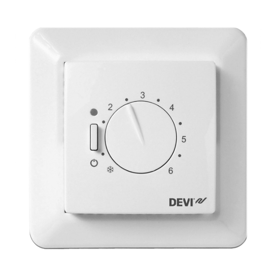
( ) 1 to 6 (each step corresponds to approximately 8°C). Furthermore, it has a LED indicator showing standby periods (green light) and heating periods (red light). More information on this product can also be found at: devireg.devi.com Installation Guide... -
Page 4: Technical Specifications
DEVIreg™ 528 Technical Specifications Operation voltage 220-240~, 50Hz Standby power consumption Max. 0.25W Relay: Resistive load Max 10A / 2300W @ 230V Inductive load cos φ= 0.3 max 1A Sensing units NTC 15kOhm at 25°C Sensing values: 0°C 42kOhm 25°C 15kOhm 50°C 6kOhm... -
Page 5: Safety Instructions
DEVIreg™ 528 IP class Protection class Class II - Dimensions 85 x 85 x 36mm Weight The product complies with the EN/IEC Standard "Automatic electrical controls for household and similar use": ▪ EN/IEC 60730-1 (general) ▪ EN/IEC 60730-2-9 (thermostat) Safety Instructions Make sure the mains supply to the thermostat is turned off before installation. -
Page 6: Mounting Instructions
DEVIreg™ 528 ▪ The sensor is to be considered as live voltage. Have this in mind if the sensor must be extended. ▪ Always connect the thermostat to continuous power supply. ▪ Do not expose the thermostat to moisture, water, dust, and excessive heat. - Page 7 DEVIreg™ 528 ▪ Place the floor sensor in a conduit in an appropriate place where it is not exposed to sunlight or draft from door openings. ▪ Equally distant and >2cm from two heating cables. ▪ The conduit should be flush with the floor surface - countersink the conduit if necessary.
- Page 8 DEVIreg™ 528 2. Connect the thermostat according to the connection diagram. LOAD LOAD Mains Max. Load 220-240V~ 10 (1) A -5°C IP31 -10T30 D528 By connecting an external timer to the terminal marked by a moon symbol (and by using for example the same phase as for the mains power supply), the thermostat can be set to reduce the temperature by 5ºC during specified periods.
-
Page 9: Settings
DEVIreg™ 528 3. Mount and reassemble the thermostat: ▪ Fasten the thermostat to a flush-mounting box or a surface-mounting box by driving the screws through the holes in each side of the thermostat. ▪ Install the frame and front cover in the reverse or- der of disassembly. - Page 10 DEVIreg™ 528 Ther- Examples of floor- Details Approximate setting for 25˚C resist- on top surface ance of floor 0.05 8 mm HDF based > 800 28˚C laminate kg/m 0.10 14 mm beech par- 650 - 800 31˚C quet kg/m 0.13 22 mm solid oak >...
-
Page 11: Warranty
DEVIreg™ 528 How to change the minimum and maximum floor tem- peratures 1. Remove the adjust- ment button. 2. Move the pins to the desired positions. 3. Put the adjustment button back in place. Warranty Y E A R Disposal Instruction Installation Guide... - Page 12 DEVIreg™ 528 Installation Guide...
- Page 13 DEVIreg™ 528 Installation Guide...
- Page 14 DEVIreg™ 528 Installation Guide...
- Page 15 This also applies to products already on order provided that such alterations can be made without subsequential changes being necessary in specifications already agreed. All trademarks in this material are property of the respective companies. DEVI and the DEVI logo- type are trademarks of Danfoss A/S.
Need help?
Do you have a question about the DEVIreg 528 and is the answer not in the manual?
Questions and answers