Advertisement
Quick Links
Download this manual
See also:
User Manual
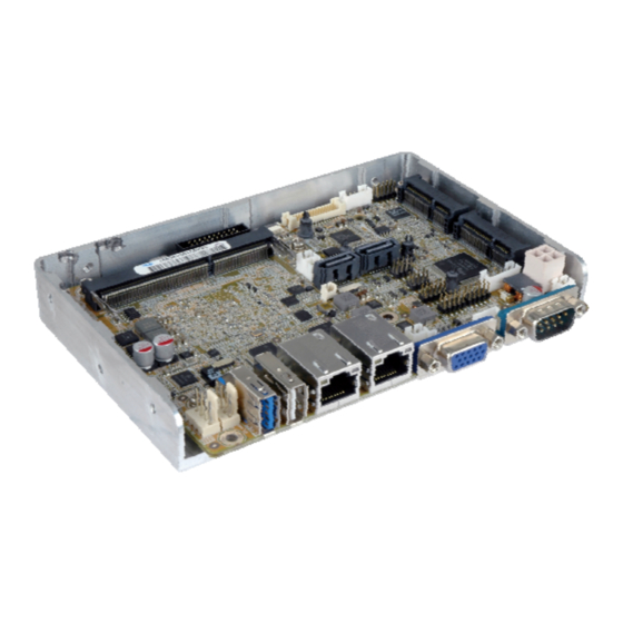
3.5" SBC with Intel® 22nm Atom™/Celeron® on-board SoC,
VGA/LVDS/iDP, Dual PCIe GbE, USB 3.0, PCIe Mini,
SATA 3Gb/s, mSATA, COM, Audio and RoHS
Quick Installation Guide
Package List
WAFER-BT-i1 package includes the following items:
1 x WAFER-BT-i1 single board computer
1 x SATA with power cable kit (P/N: 32801-000201-100-RS)
1 x Audio cable (P/N: 32000-072100-RS)
1 x Power cable (P/N: 32100-087100-RS)
1 x QIG (Quick Installation Guide)
1 x Utility CD
WAFER-BT-i1
Version 1.0
Nov 11, 2014.
©2006 Copyright by IEI Integration corp.
All rights reserved.
1
Advertisement

Subscribe to Our Youtube Channel
Related Manuals for IEI Technology WAFER-BT-i1


Summary of Contents for IEI Technology WAFER-BT-i1
-
Page 1: Quick Installation Guide
SATA 3Gb/s, mSATA, COM, Audio and RoHS WAFER-BT-i1 Quick Installation Guide Version 1.0 Nov 11, 2014. Package List WAFER-BT-i1 package includes the following items: 1 x WAFER-BT-i1 single board computer 1 x SATA with power cable kit (P/N: 32801-000201-100-RS) ... - Page 2 Specifications SoC: Intel® Atom™ E3845 on-board SoC (1.91GHz, quad-core, 2MB cache, TDP=10W) Intel® Atom™ E3827 on-board SoC (1.75GHz, dual-core, 1MB cache, TDP=8W) Intel® Atom™ E3826 on-board SoC (1.46GHz, dual-core, 1MB cache, TDP=7W) Intel® Atom™ E3825 on-board SoC (1.33GHz, dual-core, 1MB cache, TDP=6W) Intel®...
- Page 3 1 x PCIe GbE by Intel I211 controller (LAN2) Super IO: Fintek F81866 Embedded Controller: ITE IT8528E I/O Interface: 1 x PS/2 KB/MS 2 x SATA 3Gb/s with 5V SATA power connector (no RAID) 1 x USB 3.0 (on rear I/O) 5 x USB 2.0 (1 on rear I/O, 4 by pin header) 1 x RS-422/485 (by pin header) 3 x RS-232 (1 on rear I/O, 2 by pin header)
-
Page 4: Ordering Information
Dimensions: 146mm x 102mm Weight(GW/ NW): 600g / 250g Ordering Information WAFER-BT-i1-J19001-R10: 3.5” SBC supports Intel® 22nm quad-core Celeron® J1900 2.0 GHz on-board SoC with VGA/LVDS/iDP, Dual PCIe GbE, USB 3.0, PCIe Mini, SATA 3Gb/s, mSATA, COM, Audio, iRIS-1010 and RoHS ... -
Page 5: Jumpers Setting And Connectors
Jumpers setting and connectors LABEL FUNCTION PWR_BTN1 Power On/Off button pin header RST_BTN1 System Reset button pin header J_ATX_AT1 AT/ATX mode select switch J_CMOS1 Clear CMOS button COM1, COM2, COM3 Serial port, RS-232 COM4 Serial port, RS-422/485 Front Panel Pin Header D-SUB VGA connector USB1, USB4... - Page 6 PWR_BTN1: Power On/Off button pinheader PIN NO. DESCRIPTION Open Normal Operation (Default) Short Power on/off RST_BTN1: System Reset button pinheader PIN NO. DESCRIPTION Open Normal Operation (Default) Short Reset J_ATX_AT1: AT/ATX mode select switch PIN NO. DESCRIPTION Short A - B ATX Mode (default) Short B - C AT Mode...
- Page 7 COM2: (RS-232) Pinheader PIN NO. DESCRIPTION PIN NO. DESCRIPTION NDCD2 NDSR2 NRXD2 NRTS2 NTXD2 NCTS2 NDTR2 NRI2 COM3: (RS-232) Pinheader PIN NO. DESCRIPTION PIN NO. DESCRIPTION NDCD3 NDSR3 NRXD3 NRTS3 NTXD3 NCTS3 NDTR3 NRI3 COM4: RS-422/485 serial port connector DESCRIPTION DESCRIPTION RXD485# RXD485+...
- Page 8 D-SUB: VGA connector PIN NO. DESCRIPTION PIN NO. DESCRIPTION Green Blue VGAVCC HOTPLUG DDCDAT HSYNC VSYNC DDCCLK USB4: USB2.0 Port Pin Header PIN NO. DESCRIPTION PIN NO. DESCRIPTION -DATA_USB1 -DATA_USB2 +DATA_USB1 +DATA_USB2 USB1: USB2.0 Port Pin Header PIN NO. DESCRIPTION PIN NO.
- Page 9 USB3: USB3.0 Port connector PIN NO. DESCRIPTION PIN NO. DESCRIPTION USB2P0- USB2P0+ USB3P0_RXDN1 USB3P0_RXDP1 USB3P0_TXDN1 USB3P0_TXDP1 DIO1: 8 Bits Digital I/O Pin Header PIN NO. DESCRIPTION PIN NO. DESCRIPTION DGPO3 DGPO2 DGPO1 DGPO0 DGPI3 DGPI2 DGPI1 DGPI0 JSPI1: BIOS SPI ROM Programming Pin PIN NO.
- Page 10 SYS_FAN1: System smart FAN connector PIN NO. DESCRIPTION PIN NO. DESCRIPTION +12V FANIO2 FANOUT2 LED_LAN: LAN1 link LED connector PIN NO. DESCRIPTION PIN NO. DESCRIPTION +3.3VLAN LAN1_LED_LINK# LED_LAN2: LAN2 link LED connector PIN NO. DESCRIPTION PIN NO. DESCRIPTION +3.3VLAN LAN2_LED_LINK# KB_MS1: Keyboard &...
- Page 11 DP1: DP port internal pin header PIN NO. DESCRIPTION PIN NO. DESCRIPTION DPD_OB_LANE1_N DPD_OB_LANE1_P DPD_OB_LANE3_N DPD_OB_LANE3_P AUX_CTRL_DET_D DDI1_HPD# DPD_AUX_CTRL_P DPD_AUX_CTRL_N2 DPD_OB_LANE2_P DPD_OB_LANE2_N DPD_OB_LANE0_P DPD_OB_LANE0_N +3.3V SATA_PWR1, SATA_PWR2: SATA Power Connectors PIN NO. DESCRIPTION PIN NO. DESCRIPTION SATA1, SATA2: SATA 3Gb/s Drive Connectors PIN NO.
- Page 12 INV1: LCD panel backlight power connector PIN NO. DESCRIPTION PIN NO. DESCRIPTION BL_PWM +12V BL_EN J_LCD_PWR1: LCD voltage selection PIN NO. DESCRIPTION Short A- B +3.3 V (Default) Short B- C +5 V LVDS1: LVDS panel Connector PIN NO. DESCRIPTION PIN NO.
- Page 13 SW1: LVDS panel resolution selection * ON=0, OFF=1; Single=S, Dual=D 4-3-2-1 DESCRIPTION 0000 800x600 18-bit Single (Default) 0001 1024x768 18-bit Single 0010 1024x768 24-bit Single 0011 1280x768 18-bit Single 0100 1280x800 18-bit Single 0101 1280x960 18-bit Single 0110 1280x1024 24-bit Dual 0111 1366x768 18-bit Single 1000...
- Page 14 Board Layout: Jumper and Connector Locations (Unit: mm)
Need help?
Do you have a question about the WAFER-BT-i1 and is the answer not in the manual?
Questions and answers