Sign In
Upload
Manuals
Brands
IEI Technology Manuals
Motherboard
WAFER-BT-i1
IEI Technology WAFER-BT-i1 Manuals
Manuals and User Guides for IEI Technology WAFER-BT-i1. We have
2
IEI Technology WAFER-BT-i1 manuals available for free PDF download: User Manual, Quick Installation Manual
IEI Technology WAFER-BT-i1 User Manual (129 pages)
Brand:
IEI Technology
| Category:
Motherboard
| Size: 5.86 MB
Table of Contents
User Manual
1
Table of Contents
5
1 Introduction
15
Introduction
16
Model Variations
16
Figure 1-1: WAFER-BT-I1
16
Table 1-1: WAFER-BT-I1 Model Variations
16
Features
17
Connectors
17
Figure 1-2: Connectors
17
Dimensions
18
Figure 1-3: Dimensions (MM)
19
Data Flow
20
Figure 1-4: Data Flow Diagram
20
Technical Specifications
21
Table 1-2: Technical Specifications
23
2 Unpacking
24
Anti-Static Precautions
25
Unpacking Precautions
25
Packing List
26
Optional Items
27
3 Connectors
29
Peripheral Interface Connectors
30
WAFER-BT-I1 Layout
30
Figure 3-1: Connector and Jumper Locations (Front)
30
Table 3-1: Peripheral Interface Connectors
31
External Interface Panel Connectors
32
Internal Peripheral Connectors
32
DC-IN Power Connector
32
Table 3-2: Rear Panel Connectors
32
Audio Connector
33
Figure 3-2: +12V DC-IN Power Connector Location
33
Table 3-3: +12V DC-IN Power Connector Pinouts
33
Battery Connector
34
Figure 3-3: Audio Connector Location
34
Table 3-4: Audio Connector Pinouts
34
Buzzer Connector
35
Figure 3-4: Battery Connector Location
35
Figure 3-5: Buzzer Connector Location
35
Table 3-5: Battery Connector Pinouts
35
Fan Connectors
36
DDR3L SO-DIMM Slot
36
Figure 3-6: Fan Connector Locations
36
Table 3-6: Buzzer Connector Pinouts
36
Table 3-7: Fan Connector Pinouts
36
Digital I/O Connector
37
Figure 3-7: DDR3L SO-DIMM Slot Location
37
Figure 3-8: Digital I/O Connector Location
37
Display Port Connector
38
Figure 3-9: Display Port Connector Location
38
Table 3-8: Digital I/O Connector Pinouts
38
Front Panel Connector
39
Figure 3-10: Front Panel Connector Location
39
Table 3-9: Display Port Connector Pinouts
39
Iris-1010 Module Slot
40
Figure 3-11: Iris-1010 Module Slot Location
40
Table 3-10: Front Panel Connector Pinouts
40
Keyboard and Mouse Connector
41
Figure 3-12: Keyboard and Mouse Location
41
Table 3-11: Keyboard and Mouse Connector Pinouts
41
LVDS Backlight Inverter Connector
42
LVDS LCD Connector
42
Figure 3-13: Backlight Inverter Connector Location
42
Table 3-12: Backlight Inverter Connector Pinouts
42
Figure 3-14: LVDS Connector Location
43
Table 3-13: LVDS Connector Pinouts
43
LAN LED Connector
44
Pcie Mini Card Slot
44
Figure 3-15: LAN LED Connector Location
44
Table 3-14: LAN LED Connector Pinouts
44
Power Button Connector
45
Figure 3-16: Pcie Mini Card Slot Location
45
Reset Button Connector
46
Figure 3-17: Power Button Connector Location
46
Table 3-15: Power Button Connector Pinouts
46
Serial Port Connectors
47
Figure 3-18: Reset Button Connector Location
47
Figure 3-19: RS-232 Serial Port Connectors Locations
47
Table 3-16: Reset Button Connector Pinouts
47
RS-422/485 Serial Port Connector
48
Figure 3-20: RS-422/485 Connector Location
48
Table 3-17: RS-232 Serial Port Connector Pinouts
48
Table 3-18: RS-422/485 Connector Pinouts
48
SATA 3Gb/S Drive Connectors
49
Figure 3-21: SATA 3Gb/S Drive Connectors Locations
49
Table 3-19: DB-9 RS-422/485 Pinouts
49
SATA Power Connectors
50
Figure 3-22: SATA Power Connector Locations
50
Table 3-20: SATA Power Connector Pinouts
50
Smbus Connector
51
USB Connectors
51
Figure 3-23: Smbus Connectors Location
51
Table 3-21: Smbus Connectors Pinouts
51
External Peripheral Interface Connector Panel
52
Figure 3-24: USB Connectors Locations
52
Table 3-22: USB Connectors Pinouts
52
Figure 3-25: External Peripheral Interface Connector
53
Figure 3-26: LAN Connector
53
LAN Connector
53
Table 3-23: LAN Pinouts
53
Table 3-24: Connector Leds
54
Table 3-25: USB 2.0 Port Pinouts
54
Table 3-26: USB 3.0 Port Pinouts
54
USB Connectors
54
Figure 3-27: RS-232 Serial Port Connector
55
Serial Port Connector
55
Table 3-27: RS-232 Serial Port Connector Pinouts
55
VGA Connector
55
Figure 3-28: VGA Connector
56
Table 3-28: VGA Connector Pinouts
56
4 Installation
57
Anti-Static Precautions
58
Installation Considerations
58
So-DIMM Installation
60
Figure 4-1: SO-DIMM Installation
60
Full-Size Pcie Mini Card Installation
61
Figure 4-2: Removing the Retention Screw
61
Figure 4-3: Removing the Retention Screw and Standoff
62
Figure 4-4: Inserting the Full-Size Pcie Mini Card into the Slot at an Angle
62
Figure 4-5: Securing the Full-Size Pcie Mini Card
63
Half-Size Pcie Mini Card Installation
64
Figure 4-6: Removing the Retention Screw
64
Figure 4-7: Inserting the Half-Size Pcie Mini Card into the Slot at an Angle
65
Figure 4-8: Securing the Half-Size Pcie Mini Card
65
System Configuration
66
AT/ATX Mode Select Switch
66
Figure 4-9: AT/ATX Mode Select Switch Location
66
Table 4-1: AT/ATX Mode Select Switch Settings
66
Clear CMOS Button
67
LVDS Panel Resolution Selection
67
Figure 4-10: Clear CMOS Button Location
67
Table 4-2: Clear CMOS Button Settings
67
Figure 4-11: LVDS Panel Resolution Selection Switch Location
68
Table 4-3: LVDS Panel Resolution Selection
68
LVDS Voltage Selection
69
Figure 4-12: LVDS Voltage Selection Jumper Location
69
Table 4-4: LVDS Voltage Selection Jumper Settings
69
Flash Descriptor Security Override Jumper
70
Figure 4-13: Flash Descriptor Security Override Jumper Location
70
Table 4-5: Flash Descriptor Security Override Jumper Settings
70
Chassis Installation
71
Heat Sink Enclosure
71
Motherboard Installation
71
Internal Peripheral Device Connections
72
Audio Kit Installation
72
Figure 4-14: Motherboard Installation Example
72
SATA Drive Connection
73
Figure 4-15: Audio Kit Cable Connection
73
Single RS-232 Cable
74
Figure 4-16: SATA Drive Cable Connection
74
Figure 4-17: Single RS-232 Cable Installation
75
5 Bios
76
Introduction
77
Starting Setup
77
Using Setup
77
Getting Help
78
Unable to Reboot after Configuration Changes
78
BIOS Menu Bar
78
Table 5-1: BIOS Navigation Keys
78
Main
79
BIOS Menu 1: Main
79
Advanced
80
ACPI Settings
81
BIOS Menu 2: Advanced
81
BIOS Menu 3: ACPI Configuration
81
Super IO Configuration
82
BIOS Menu 4: Super IO Configuration
82
Serial Port N Configuration
83
Serial Port 1 Configuration
83
BIOS Menu 5: Serial Port N Configuration Menu
83
Serial Port 2 Configuration
84
Serial Port 3 Configuration
85
Serial Port 4 Configuration
86
Hardware Monitor
87
BIOS Menu 6: Hardware Monitor
87
Smart Fan Mode Configuration
88
BIOS Menu 7: Smart Fan Mode Configuration
88
RTC Wake Settings
91
BIOS Menu 8: RTC Wake Settings
91
Serial Port Console Redirection
92
BIOS Menu 9: Serial Port Console Redirection
92
Console Redirection Settings
93
BIOS Menu 10: Console Redirection Settings
93
CPU Configuration
95
BIOS Menu 11: CPU Configuration
95
IDE Configuration
96
BIOS Menu 12: IDE Configuration
96
USB Configuration
97
BIOS Menu 13: USB Configuration
97
Chipset
98
North Bridge Configuration
99
BIOS Menu 14: Chipset
99
BIOS Menu 15: Northbridge Chipset Configuration
99
Intel IGD Configuration
100
BIOS Menu 16: Integrated Graphics
100
Southbridge Configuration
102
BIOS Menu 17: Southbridge Chipset Configuration
102
PCI Express Configuration
103
BIOS Menu 18: Console Redirection Settings
103
Security
104
BIOS Menu 19: Security
104
Boot
105
BIOS Menu 20: Boot
105
BIOS Menu 21:Exit
107
A Regulatory Compliance
109
B Product Disposal
111
C Bios Menu Options
113
D Terminology
116
E Digital I/O Interface
121
F Watchdog Timer
124
G Hazardous Materials Disclosure
127
Advertisement
IEI Technology WAFER-BT-i1 Quick Installation Manual (14 pages)
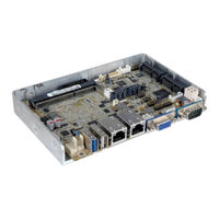
3.5” SBC with Intel 22nm Atom/Celeron on-board SoC VGA/LVDS/iDP, Dual PCIe GbE, USB 3.0, PCIe Mini, SATA 3Gb/s, mSATA, COM, Audio and RoHS
Brand:
IEI Technology
| Category:
Desktop
| Size: 0.2 MB
Advertisement
Related Products
IEI Technology WAFER-BT
IEI Technology WAFER-BW-N3-R10
IEI Technology WAFER-BW-N2-R10
IEI Technology WAFER-BW-N1-R10
IEI Technology WAFER-BW Series
IEI Technology WAFER-BW-N4-R20
iEi Integration WAFER-BW-N3-R20
iEi Integration WAFER-BW-N2-R20
iEi Integration WAFER-BW-N1-R20
IEI Technology WAFER-BW
IEI Technology Categories
Motherboard
Touch Panel
Computer Hardware
Single board computers
Desktop
More IEI Technology Manuals
Login
Sign In
OR
Sign in with Facebook
Sign in with Google
Upload manual
Upload from disk
Upload from URL