Omron GRT1-ML2 Manual
Smartslice communication unit
Hide thumbs
Also See for GRT1-ML2:
- Hardware reference manual (195 pages) ,
- Programming manual (362 pages) ,
- System configuration manual (11 pages)
Table of Contents
Advertisement
Quick Links
Contents
1
Hardware reference ...................................................................................................................................................................................... 2
1.1
GRT1-ML2 overview.........................................................................................................................................................................................................................2
1.1.1
Unit dipswitches..................................................................................................................................................................................................................2
1.1.2
LED indicators ....................................................................................................................................................................................................................3
1.1.3
Communication dipswitches ...............................................................................................................................................................................................4
1.1.4
Rotary switch ......................................................................................................................................................................................................................5
1.1.5
Power supply connector .....................................................................................................................................................................................................5
1.2
Specifications....................................................................................................................................................................................................................................6
1.3
Installation.........................................................................................................................................................................................................................................8
1.3.1
Connections........................................................................................................................................................................................................................8
1.3.2
Wiring .................................................................................................................................................................................................................................8
1.3.3
Replace ............................................................................................................................................................................................................................10
2
Setup and usage ......................................................................................................................................................................................... 11
2.1
MECHATROLINK-II I/O mapping ...................................................................................................................................................................................................11
2.1.1
Unit numbers ....................................................................................................................................................................................................................11
2.1.2
SmartSlice I/O mapping....................................................................................................................................................................................................11
2.1.3
GRT1-ML2 status word ....................................................................................................................................................................................................13
2.2
GRT1-ML2 functions.......................................................................................................................................................................................................................14
2.2.1
Table registration..............................................................................................................................................................................................................14
2.2.2
Online replacement ..........................................................................................................................................................................................................14
3
Troubleshooting.......................................................................................................................................................................................... 16
3.1
Unit power supply errors.................................................................................................................................................................................................................16
3.2
I/O power supply errors ..................................................................................................................................................................................................................16
3.3
Unit errors .......................................................................................................................................................................................................................................16
3.4
SmartSlice I/O errors ......................................................................................................................................................................................................................17
Timing .......................................................................................................................................................................................................... 19
A.1
Timing concepts..............................................................................................................................................................................................................................19
A.1.1
Refresh cycles ..................................................................................................................................................................................................................19
A.1.2
Paging ..............................................................................................................................................................................................................................19
A.2
Examples ........................................................................................................................................................................................................................................20
A.2.1
Example 1.........................................................................................................................................................................................................................21
A.2.2
Example 2.........................................................................................................................................................................................................................21
GRT1-ML2 MANUAL
1
Advertisement
Table of Contents

Related Manuals for Omron GRT1-ML2


Summary of Contents for Omron GRT1-ML2
-
Page 1: Table Of Contents
Replace ............................................10 Setup and usage ......................................11 MECHATROLINK-II I/O mapping ........................................11 2.1.1 Unit numbers ............................................11 2.1.2 SmartSlice I/O mapping........................................11 2.1.3 GRT1-ML2 status word ........................................13 GRT1-ML2 functions............................................14 2.2.1 Table registration..........................................14 2.2.2 Online replacement ..........................................14 Troubleshooting......................................16 Unit power supply errors..........................................16 I/O power supply errors ..........................................16 Unit errors ...............................................16... -
Page 2: Hardware Reference
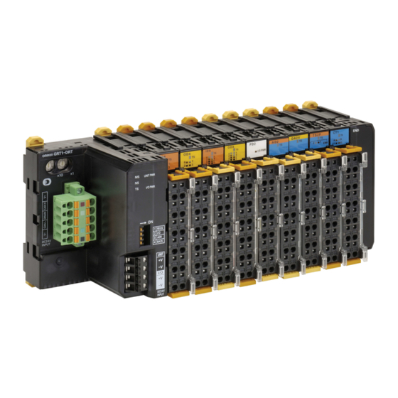
Label Description Rotary switch GRT1-ML2 overview Communication dipswitches The GRT1-ML2 SmartSlice Communication Unit controls data exchange 1.1.1 Unit dipswitches between a TJ1-MC__ Motion Controller Unit (via a connected TJ1-ML__ MECHATROLINK-II Master Unit) and SmartSlice I/O Units over a MECHATROLINK-II network. For more information on SmartSlice I/O Units, refer to the GRT1 Series SmartSlice I/O Units Operation Manual (W455). -
Page 3: Led Indicators
It is recommended to do a registration of the SmartSlice I/O Units (see section 2.2.1). • It is recommended to set dipswitches 1, 3 and 4 on after this registration. The factory setting of all dipswitches is OFF. 1.1.2 LED indicators UNIT PWR ALARM ML COM I/O PWR GRT1-ML2 MANUAL... -
Page 4: Communication Dipswitches
SmartSlice I/O Unit added to the system with the command MECHATROLINK(unit,0), the ML COM (every LED goes on. second) • When the GRT1-ML2 loses the MECHATROLINK-II communi- Flashing Backup/Restore function operating: cation with the master, or when the command (every •... -
Page 5: Rotary Switch
1. Turn off the Unit power supply of the GRT1-ML2. To make the MECHATROLINK-II address of the unit valid, do one The address of the GRT1-ML2 is read only at power on. Setting of these steps: the new address when the power is on has no effect. -
Page 6: Specifications
Storage temperature 1.2.1 Supported SmartSlice I/O Units Vibration resistance 10 to 57 Hz, 0.7 mm amplitude The GRT1-ML2, in combination with the Trajexia system, supports these 57 to 150 Hz, acceleration: 49 m/s SmartSlice I/O Units. Shock resistance 150 m/s... - Page 7 2 analog outputs, voltage 10 V, 0-10 V, 0-5 V, 1-5 V GRT1-DA2V REGS 2 analog outputs, current 0-20 mA, 4-20 mA GRT1-DA2C BACK UNIT UNIT -V -V -V -V DC24V DC24V INPUT INPUT 26.3 28.8 17.1 61.2 36.8 69.7 GRT1-ML2 MANUAL...
-
Page 8: Installation
End Units and end plates. • Install the GRT1-ML2 and the SmartSlice I/O Units on a DIN rail. To install a GRT1-ML2 on the DIN rail, press it onto the DIN track from the 1.3.2 Wiring front, and press the unit firmly until it clicks. Check that all DIN rail sliders of the unit are locked onto the DIN rail. - Page 9 To supply power to the units and the I/O devices, connect the power supply wires to the power supply terminals of the GRT1-ML2. If the wire ends have pin terminals, just insert the pin terminals in the power supply terminals.
-
Page 10: Replace
8 to 10 mm. 1.3.3 Replace The GRT1-ML2 is a unit that is part of a network. If the GRT1-ML2 is damaged, it effects the whole network. Make sure that a dam- aged GRT1-ML2 is repaired immediately. To replace the unit, follow these rules: •... -
Page 11: Setup And Usage
The I/O data from GRT1-ML2 units is mapped in the TJ1-MC__ in order of the GRT1-ML2 addresses. For example, the I/O data of a GRT1-ML2 unit with address 67 hex is mapped before the I/O data of a GRT1-ML2 unit with Analog Inputs Analog Ouputs address 68 hex. - Page 12 • 0 is the number of analog outputs The configuration of the GRT1-ML2 units in the example above is: Depending on the actual GRT1-ML2 configurations, gaps are introduced in the available digital I/O ranges. In the example above, the range of GRT1-ML2: 63(32/8/0/0/0/0/6) distributed digital inputs and outputs is [32–127], but there are gaps in the...
-
Page 13: Grt1-Ml2 Status Word
MECHATROLINK(unit,36,station,vr) The GRT1-ML2 status flags give the status of the connection between the GRT1-ML2 and the SmartSlice I/O Units, and the status of the SmartSlice I/ where: O Units. The status flags are 1 word in size. Their information is transferred •... -
Page 14: Grt1-Ml2 Functions
To disable the registered table, make sure that unit dipswitch 1 (REGS) Output Output is set to OFF before the power is turned on. In this case, the GRT1-ML2 Registered table Actual configuration automatically detects the actual I/O configuration and starts the communication. - Page 15 • When a unit is removed from the I/O communication, the withdrawn flag of the unit is set on and the TS LED on the GRT1-ML2 flashes red. • If I/O power supply of the unit is not turned off, there can be false output signals, false input signals and electrical schocks.
-
Page 16: Troubleshooting
I/O Unit reports its correct status too late to the GRT1-ML2, the status word or not enough supply terminal of the GRT1-ML2 has bit 13 set, which means that there is an error or a power supply to • Check that the supplied power is in the required warning in the SmartSlice system. -
Page 17: Smartslice I/O Errors
I/O points and turn the greater than the maximum power on again Flashing Green Restore operation in progress Wait until the restore operation is (every complete 0.5 sec- Backup operation in progress Wait until the backup operation is onds) complete GRT1-ML2 MANUAL... - Page 18 Are more than 128 bytes of I/O data used? • Has the I/O configuration changed since the I/O configu- ration table was registered? Green The Slice bus operates normally N/A 1. The TS LED is lit for 2 seconds. GRT1-ML2 MANUAL...
-
Page 19: A Timing
MECHATROLINK-II protocol is 27 bytes. This is called a page. If the A.1.1 Refresh cycles GRT1-ML2 transfers more than 27 bytes of input and/or output data, the data is divided into multiple pages. These pages are transferred in multiple There are two refresh cycles involved in the timing issues: servo periods. -
Page 20: Examples
OFF delay. CUout The Trajexia servo period Typically 1ms 1. 2 is added to PDsize because the GRT1-ML2 produces 2 bytes of input SERVO See the BASIC command SERVO_PERIOD in the Trajexia Programming data (the GRT1-ML2 status word). -
Page 21: Example 2
1. For the contribution of the individual slices to the I/O data size, see sec- 0 ms ≤ T ≤ 2 ms GRT1-AD2 ON/OFF tion 2-2-2 of the GRT1 Series SmartSlice I/O Units Operation Manual 0 ms ≤ T ≤ 2 ms GRT1-DA2 (W455) ON/OFF Furthermore, T = 1 ms. SERVO GRT1-ML2 MANUAL... - Page 22 ≤ 1.0 + 2.0 + 1.104 + 1.004 + 1.5 = 6.608 ms GRT1-DA2 output response time SYNC MLout ON/OFF 0 + 2.0 + 0.1 + 1.004 + 2= 5.104 ms ≤ T ≤ 1.0 + 2.0 + 1.104 + 1.004 + 2 = 7.108 ms GRT1-ML2 MANUAL...
Need help?
Do you have a question about the GRT1-ML2 and is the answer not in the manual?
Questions and answers