
Related Manuals for Omron NX-SL series


Summary of Contents for Omron NX-SL series
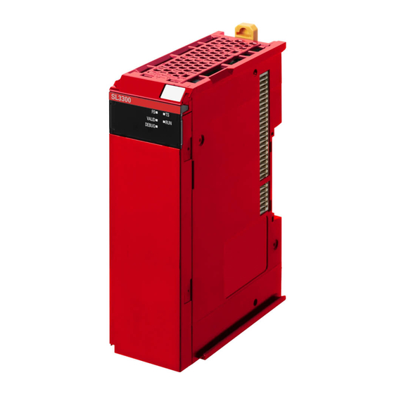
- Page 1 Machine Automation Controller NX-series Safety Control Unit Instructions Reference Manual NX-SL Z931-E1-04...
- Page 2 No patent liability is assumed with respect to the use of the information contained herein. Moreover, because OMRON is constantly striving to improve its high-quality products, the information contained in this manual is subject to change without notice. Every precaution has been taken in the preparation of this manual. Neverthe- less, OMRON assumes no responsibility for errors or omissions.
-
Page 3: Introduction
Introduction Introduction Thank you for purchasing Machine Automation Controller NX-series Safety Control Units. This manual contains information that is necessary to use the NX-series Safety Control Units. Please read this manual and make sure you understand the functionality and performance of the NX-series Safety Control Units before you attempt to use them in a control system. -
Page 4: Table Of Contents
CONTENTS CONTENTS Introduction ......................1 Intended Audience............................1 Applicable Products ............................. 1 Relevant Manuals ..................... 7 Manual Structure ...................... 8 Page Structure ............................. 8 Special Information ............................9 Terms and Conditions Agreement ................ 10 Warranty, Limitations of Liability ........................ 10 Application Considerations ........................ - Page 5 CONTENTS Section 2 Standard Functions Table of Standard Functions ....................2-2 Execution Control Instructions ..........2-5 JUMP and LABEL........................
- Page 6 CONTENTS Math Instructions ............. 2-55 ADD ............................
- Page 7 CONTENTS SF_TestableSafetySensor ....................4-113 SF_TwoHandControlTypeII ....................4-124 SF_TwoHandControlTypeIII ....................4-129 Index 2 NX-series Safety Control Unit Instructions Reference Manual (Z931)
- Page 8 CONTENTS NX-series Safety Control Unit Instructions Reference Manual (Z931)
-
Page 9: Relevant Manuals
Relevant Manuals Relevant Manuals The information for this product is divided between two manuals as shown in the following table. Read all of the manuals that are relevant to your system configuration and application before you use the product. Most operations are performed from the Sysmac Studio Automation Software. Refer to the Sysmac Studio Version 1 Operation Manual (Cat. -
Page 10: Manual Structure
Manual Structure Manual Structure Page Structure The following page structure is used in this manual. Level-2 heading Level-1 section number Ladder Diagram Instructions Level-2 Gives the number of the section. heading Instruction Name Page LD and LDN Load/ 2-14 Load NOT AND and ANDN AND/ 2-16... -
Page 11: Special Information
Manual Structure Level-1 heading 2 Instruction Descriptions Level-2 heading OR and ORN Level-3 heading Level-3 heading Give the current headings. Takes the logical OR of the value of a BOOL variable and the execution condition. ORN: Takes the logical OR of the inverse of the value of a BOOL variable and the execution condi- tion. -
Page 12: Terms And Conditions Agreement
Omron’s exclusive warranty is that the Products will be free from defects in materials and workman- ship for a period of twelve months from the date of sale by Omron (or such other period expressed in writing by Omron). Omron disclaims all other warranties, express or implied. -
Page 13: Application Considerations
Disclaimers Performance Data Data presented in Omron Company websites, catalogs and other materials is provided as a guide for the user in determining suitability and does not constitute a warranty. It may represent the result of Omron’s test conditions, and the user must correlate it to actual application requirements. Actual perfor- mance is subject to the Omron’s Warranty and Limitations of Liability. - Page 14 Terms and Conditions Agreement NX-series Safety Control Unit Instructions Reference Manual (Z931)
-
Page 15: Safety Precautions
Safety Precautions Safety Precautions Refer to the following manual for safety precautions. • NX-series Safety Control Unit User’s Manual (Cat No. Z930) NX-series Safety Control Unit Instructions Reference Manual (Z931) -
Page 16: Precautions For Safe Use
Precautions for Safe Use Precautions for Safe Use Refer to the following manual for precautions for the safe use of the Safety Control Unit. • NX-series Safety Control Unit User’s Manual (Cat No. Z930) NX-series Safety Control Unit Instructions Reference Manual (Z931) -
Page 17: Precautions For Correct Use
Precautions for Correct Use Precautions for Correct Use Refer to the following manual for precautions for the correct use of the Safety Control Unit. • NX-series Safety Control Unit User’s Manual (Cat No. Z930) NX-series Safety Control Unit Instructions Reference Manual (Z931) -
Page 18: Regulations And Standards
• cULus: Listed (UL508) and ANSI/ISA 12.12.01 *1. Certification was received for applications in which OMRON FSoE devices are connected to each other. The NX-series Safety Control Units allow you to build a safety control system that meets the following standards. -
Page 19: Conformance To En Iso 13849-1 And En 62061
50178. Do not allow the power supply cable length to exceed 3 m. We recommend that you use the OMRON S8JX-series Power Supplies. EMC standard compli- ance was confirmed for the recommended Power Supplies. • NX-series Units that comply with EC Directives also conform to the Common Emission Standard (EN 61131-2). -
Page 20: Conformance To Kc Standards
Sellers and/or users need to take note of this. Software Licenses and Copyrights This product incorporates certain third party software. The license and copyright information associated with this software is available at http://www.fa.omron.co.jp/nj_info_e/. NX-series Safety Control Unit Instructions Reference Manual (Z931) -
Page 21: Unit Versions
Lot number Gives the lot number of the Unit. DDMYY: Lot number, : Used by OMRON. “M” gives the month (1 to 9: January to September, X: October, Y: November, Z: December) NX-series Safety Control Unit Instructions Reference Manual (Z931) - Page 22 Gives the lot number and unit version of the Unit. unit version • DDMYY: Lot number, : Used by OMRON. “M” gives the month (1 to 9: January to September, X: October, Y: November, Z: December) • 1: Unit version The decimal portion of the unit version is omitted.
-
Page 23: Unit Versions And Sysmac Studio Versions
Unit Versions • Hardware version • Software version The software version is displayed only for Units that contain software. Unit Versions and Sysmac Studio Versions The functions that are supported depend on the unit version of the Unit. The version of Sysmac Studio that supports the functions that were added for an upgrade is also required to use those functions. -
Page 24: Related Manuals
Related Manuals Related Manuals The following manuals are related. Use these manuals for reference. Manual name Cat. No. Model numbers Application Description NX-series Safety Con- Z931 NX-SL Learning about the The instructions for the Safety CPU Unit are described. trol Unit Instructions specifications of When programming, use this manual together with the Reference Manual... -
Page 25: Terminology
Terminology Terminology Refer to the NX-series Safety Control Unit User’s Manual (Cat. No. Z930) for the definitions of terms that are used in this manual. NX-series Safety Control Unit Instructions Reference Manual (Z931) -
Page 26: Revision History
Revision History Revision History A manual revision code appears as a suffix to the catalog number at the bottom left of the front and back covers of the manual. Cat. No. Z931-E1-04 Revision code Revision code Date Revised content June 2013 Original production September 2013 Corrected mistakes. -
Page 27: Sections In This Manual
Sections in this Manual Sections in this Manual Introduction to Instructions for Safety Control Units and Interpreting Instruction Descriptions Standard Functions Safety Standard Function Blocks Safety Function Blocks Index NX-series Safety Control Unit Instructions Reference Manual (Z931) - Page 28 Sections in this Manual NX-series Safety Control Unit Instructions Reference Manual (Z931)
- Page 29 Introduction to Instructions for Safety Control Units and Interpreting Instruction This section provides an introduction to the instructions for Safety Control Units and tells how to interpret the instruction descriptions. 1-1 Types of Instructions ......... . . 1-2 1-2 Interpreting Instruction Descriptions .
-
Page 30: Types Of Instructions
1 Introduction to Instructions for Safety Control Units and Interpreting Instruction Descriptions Types of Instructions The following three types of instructions can be used with the Safety Control Units. Type Description Standard functions These function instructions do not use safety data. They include program execution control instructions, data type conversion instructions, Boolean operation instructions, math instructions, comparison instructions, etc. -
Page 31: Interpreting Instruction Descriptions
1 Introduction to Instructions for Safety Control Units and Interpreting Instruction Descriptions Interpreting Instruction Descriptions The notation that is used to describe instructions is explained in this section. 1-2-1 Items The following items are provided. The order of the items is not the same for all instructions. If there are items that are specific to one type of instruction, they are explained in the section for each instruction type. -
Page 32: Safety Data Types And Standard Data Types
1 Introduction to Instructions for Safety Control Units and Interpreting Instruction Descriptions Item Description Function The function of the instruction is described. Additional Informa- Additional information on the function of the instruction is provided. This includes related tion instructions and helpful information for application of the instruction. Precautions for Cor- Precautions for application of the instruction are given. -
Page 33: Timer Set Values
1 Introduction to Instructions for Safety Control Units and Interpreting Instruction Descriptions 1-2-4 Timer Set Values Time set values, such as those for DiscrepancyTime or the OFF-Delay Timer instruction, operate in increments of the safety task period. The timer error is +1 safety task period. Every safety task period, a timer value is checked to see if it has reached the set time. - Page 34 1 Introduction to Instructions for Safety Control Units and Interpreting Instruction Descriptions 1 - 6 NX-series Safety Control Unit Instructions Reference Manual (Z931)
- Page 35 Standard Functions This section gives the specifications of the standard functions that you can use for NX-series Safety Control Units. Table of Standard Functions ........2-2 Execution Control Instructions .
-
Page 36: Standard Functions
2 Standard Functions Table of Standard Functions Type Instruction Name Description Page Execution control Jump Jump Moves processing to the P. 2-6 jump destination specified by a label. Return Return Returns control to the pro- P. 2-8 cess that called the POU without executing any pro- cessing after RETURN. - Page 37 2 Standard Functions Type Instruction Name Description Page Data type Integer to DINT_TO_BOOL Convert Converts a DINT variable to P. 2-29 conversion Boolean DINT to a BOOL variable. BOOL INT_TO_BOOL Convert INT Converts an INT variable to P. 2-30 to BOOL a BOOL variable.
- Page 38 2 Standard Functions Type Instruction Name Description Page Boolean operations Logical AND Performs a logical AND on P. 2-52 multiple Boolean variables. Logical OR Performs a logical OR on P. 2-52 multiple Boolean variables. Exclusive Performs an exclusive logi- P. 2-52 logical OR cal OR on multiple Boolean variables.
-
Page 39: Execution Control Instructions
Execution Control Instructions Type Instruction Name Description Page Execution control Jump Jump Moves processing to the P. 2-6 jump destination specified by a label. Return Return Returns control to the pro- P. 2-8 cess that called the POU without executing any pro- cessing after RETURN. -
Page 40: Jump And Label
2 Standard Functions JUMP and LABEL This function moves processing to the jump destination specified by a label. Instruction Name FB/FUN Graphic expression JUMP Jump Label LABEL Label Label: Variables There are no variables for these instructions. Function When the execution condition is TRUE, the JUMP instruction moves processing to the jump destination specified by a label in the program. - Page 41 2 Standard Functions Additional Information • You cannot jump upward in the networks. • You can use the same label as the jump destination for more than one JUMP instruction. • You can set only a label in a network, or you can set both programming and a label in a network. Precautions for Correct Use •...
-
Page 42: Return
2 Standard Functions RETURN This function returns control to the process that called the POU without executing any processing after RETURN. Instruction Name FB/FUN Graphic expression RETURN Return RETURN Variables There are no variables for these instructions. Function When the execution condition is TRUE, control is returned to the location that called the POU without executing any processing after RETURN. -
Page 43: Data Type Conversion Instructions
Data Type Conversion Instructions Type Instruction Name Description Page Data type Boolean to BOOL_TO_INT Convert Converts a BOOL variable P. 2-12 conversion integer BOOL to INT to an INT variable. BOOL_TO_DINT Convert Converts a BOOL variable P. 2-13 BOOL to to a DINT variable. - Page 44 2 Standard Functions Type Instruction Name Description Page Data type Bit string to inte- BYTE_TO_INT Convert Converts a BYTE variable to P. 2-16 conversion BYTE to INT an INT variable. BYTE_TO_DINT Convert Converts a BYTE variable to P. 2-17 BYTE to a DINT variable.
- Page 45 2 Standard Functions Type Instruction Name Description Page Data type Integer to DINT_TO_TIME Convert Converts a DINT variable to P. 2-42 conversion duration DINT to a TIME variable. TIME INT_TO_TIME Convert INT Converts an INT variable to P. 2-43 to TIME a TIME variable.
-
Page 46: Bool_To_Int
2 Standard Functions BOOL_TO_INT This function converts a BOOL variable to an INT variable. Instruction Name FB/FUN Graphic expression BOOL_TO_INT Convert BOOL to BOOL_TO_INT Variables Name Description Valid range Default Data to con- Input Data to con- TRUE or FALSE FALSE vert vert... -
Page 47: Bool_To_Dint
2 Standard Functions BOOL_TO_DINT This function converts a BOOL variable to a DINT variable. Instruction Name FB/FUN Graphic expression BOOL_TO_DINT Convert BOOL to BOOL_TO_DINT DINT Variables Name Description Valid range Default Data to con- Input Data to con- TRUE or FALSE FALSE vert vert... -
Page 48: Bool_To_Time
2 Standard Functions BOOL_TO_TIME This function converts a BOOL variable to a TIME variable. Instruction Name FB/FUN Graphic expression BOOL_TO_TIME Convert BOOL to BOOL_TO_TIME TIME Variables Name Description Valid range Default Data to con- Input Data to con- TRUE or FALSE FALSE vert vert... -
Page 49: Bool_To_Word
2 Standard Functions BOOL_TO_WORD This function converts a BOOL variable to a WORD variable. Instruction Name FB/FUN Graphic expression BOOL_TO_WORD Convert BOOL to BOOL_TO_WORD WORD Variables Name Description Valid range Default Data to con- Input Data to con- TRUE or FALSE FALSE vert vert... -
Page 50: Byte_To_Int
2 Standard Functions BYTE_TO_INT This function converts a BYTE variable to an INT variable. Instruction Name FB/FUN Graphic expression BYTE_TO_INT Convert BYTE to BYTE_TO_INT Variables Name Description Valid range Default Data to con- Input Data to con- BYTE#16#00 to FF BYTE#16#00 vert vert... -
Page 51: Byte_To_Dint
2 Standard Functions BYTE_TO_DINT This function converts a BYTE variable to a DINT variable. Instruction Name FB/FUN Graphic expression BYTE_TO_DINT Convert BYTE to BYTE_TO_DINT DINT Variables Name Description Valid range Default Data to con- Input Data to con- BYTE#16#00 to FF BYTE#16#00 vert vert... -
Page 52: Word_To_Int
2 Standard Functions WORD_TO_INT This function converts a WORD variable to an INT variable. Instruction Name FB/FUN Graphic expression WORD_TO_INT Convert WORD WORD_TO_INT to INT Variables Name Description Valid range Default Data to con- Input Data to con- WORD#16#0000 to FFFF WORD#16#0000 vert vert Conversion... - Page 53 2 Standard Functions Precautions for Correct Use • The input condition depends on whether the output is safety data or standard data. If the condition is not met, a building error will occur. • If you set a safety data type variable for the output terminal, set a safety data type variable for the input terminal as well.
-
Page 54: Word_To_Dint
2 Standard Functions WORD_TO_DINT This function converts a WORD variable to a DINT variable. Instruction Name FB/FUN Graphic expression WORD_TO_DINT Convert WORD WORD_TO_DINT to DINT Variables Name Description Valid range Default Data to con- Input Data to con- WORD#16#0000 to FFFF WORD#16#0000 vert vert Conversion... -
Page 55: Dword_To_Dint
2 Standard Functions DWORD_TO_DINT This function converts a DWORD variable to a DINT variable. Instruction Name FB/FUN Graphic expression DWORD_TO_DINT Convert DWORD DWORD_TO_DINT to DINT Variables Name Description Valid range Default Data to con- Input Data to con- DWORD#16#00000000 DWORD#16#00000000 vert vert to FFFFFFFF... - Page 56 2 Standard Functions Precautions for Correct Use • The input condition depends on whether the output is safety data or standard data. If the condition is not met, a building error will occur. • If you set a safety data type variable for the output terminal, set a safety data type variable for the input terminal as well.
-
Page 57: Byte_To_Time
2 Standard Functions BYTE_TO_TIME This function converts a BYTE variable to a TIME variable. Instruction Name FB/FUN Graphic expression BYTE_TO_TIME Convert BYTE to BYTE_TO_TIME TIME Variables Name Description Valid range Default Data to con- Input Data to con- BYTE#16#00 to FF BYTE#16#00 vert vert... -
Page 58: Word_To_Time
2 Standard Functions WORD_TO_TIME This function converts a WORD variable to a TIME variable. Instruction Name FB/FUN Graphic expression WORD_TO_TIME Convert WORD WORD_TO_TIME to TIME Variables Name Description Valid range Default Data to con- Input Data to con- WORD#16#0000 to FFFF WORD#16#0000 vert vert Conversion... -
Page 59: Dword_To_Time
2 Standard Functions DWORD_TO_TIME This function converts a DWORD variable to a TIME variable. Instruction Name FB/FUN Graphic expression DWORD_TO_TIME Convert DWORD DWORD_TO_TIME to TIME Variables Name Description Valid range Default Data to con- Input Data to con- DWORD#16#00000000 DWORD#16#00000000 vert vert to FFFFFFFF... -
Page 60: Byte_To_Word
2 Standard Functions BYTE_TO_WORD This function converts a BYTE variable to a WORD variable. Instruction Name FB/FUN Graphic expression BYTE_TO_WORD Convert BYTE to BYTE_TO_WORD WORD Variables Name Description Valid range Default Data to con- Input Data to con- BYTE#16#00 to FF BYTE#16#00 vert vert... -
Page 61: Word_To_Byte
2 Standard Functions WORD_TO_BYTE This function converts a WORD variable to a BYTE variable. Instruction Name FB/FUN Graphic expression WORD_TO_BYTE Convert WORD WORD_TO_BYTE to BYTE Variables Name Description Valid range Default Data to con- Input Data to con- WORD#16#0000 to 00FF WORD#16#0000 vert vert... -
Page 62: Word_To_Dword
2 Standard Functions WORD_TO_DWORD This function converts a WORD variable to a DWORD variable. Instruction Name FB/FUN Graphic expression WORD_TO_DWORD Convert WORD WORD_TO_DWORD to DWORD Variables Name Description Valid range Default Data to con- Input Data to con- WORD#16#0000 to FFFF WORD#16#0000 vert vert Conversion... -
Page 63: Dint_To_Bool
2 Standard Functions DINT_TO_BOOL This function converts a DINT variable to a BOOL variable. Instruction Name FB/FUN Graphic expression DINT_TO_BOOL Convert DINT to DINT_TO_BOOL BOOL Variables Name Description Valid range Default Data to con- Input Data to con- DINT#−2147483648 to DINT#0 vert vert... -
Page 64: Int_To_Bool
2 Standard Functions INT_TO_BOOL This function converts an INT variable to a BOOL variable. Instruction Name FB/FUN Graphic expression INT_TO_BOOL Convert INT to INT_TO_BOOL BOOL Variables Name Description Valid range Default Data to con- Input Data to con- INT#−32768 to 32767 INT#0 vert vert... -
Page 65: Dint_To_Byte
2 Standard Functions DINT_TO_BYTE This function converts a DINT variable to a BYTE variable. Instruction Name FB/FUN Graphic expression DINT_TO_BYTE Convert DINT to DINT_TO_BYTE BYTE Variables Name Description Valid range Default Data to con- Input Data to con- DINT#0 to 255 DINT#0 vert vert... -
Page 66: Dint_To_Dword
2 Standard Functions DINT_TO_DWORD This function converts a DINT variable to a DWORD variable. Instruction Name FB/FUN Graphic expression DINT_TO_DWORD Convert DINT to DINT_TO_DWORD DWORD Variables Name Description Valid range Default Data to con- Input Data to con- DINT#−2147483648 to DINT#0 vert vert... - Page 67 2 Standard Functions Precautions for Correct Use • The input condition depends on whether the output is safety data or standard data. If the condition is not met, a building error will occur. • If you set a safety data type variable for the output terminal, set a safety data type variable for the input terminal as well.
-
Page 68: Dint_To_Word
2 Standard Functions DINT_TO_WORD This function converts a DINT variable to a WORD variable. Instruction Name FB/FUN Graphic expression DINT_TO_WORD Convert DINT to DINT_TO_WORD WORD Variables Name Description Valid range Default Data to con- Input Data to con- DINT#0 to 65535 DINT#0 vert vert... -
Page 69: Int_To_Byte
2 Standard Functions INT_TO_BYTE This function converts an INT variable to a BYTE variable. Instruction Name FB/FUN Graphic expression INT_TO_BYTE Convert INT to INT_TO_BYTE BYTE Variables Name Description Valid range Default Data to con- Input Data to con- INT#0 to 255 INT#0 vert vert... -
Page 70: Int_To_Dword
2 Standard Functions INT_TO_DWORD This function converts an INT variable to a DWORD variable. Instruction Name FB/FUN Graphic expression INT_TO_DWORD Convert INT to INT_TO_DWORD DWORD Variables Name Description Valid range Default Data to con- Input Data to con- INT#−32768 to 32767 INT#0 vert vert... - Page 71 2 Standard Functions Precautions for Correct Use • The input condition depends on whether the output is safety data or standard data. If the condition is not met, a building error will occur. • If you set a safety data type variable for the output terminal, set a safety data type variable for the input terminal as well.
-
Page 72: Int_To_Word
2 Standard Functions INT_TO_WORD This function converts an INT variable to a WORD variable. Instruction Name FB/FUN Graphic expression INT_TO_WORD Convert INT to INT_TO_WORD WORD Variables Name Description Valid range Default Data to con- Input Data to con- INT#−32768 to 32767 INT#0 vert vert... - Page 73 2 Standard Functions Precautions for Correct Use • The input condition depends on whether the output is safety data or standard data. If the condition is not met, a building error will occur. • If you set a safety data type variable for the output terminal, set a safety data type variable for the input terminal as well.
-
Page 74: Dint_To_Int
2 Standard Functions DINT_TO_INT This function converts a DINT variable to an INT variable. Instruction Name FB/FUN Graphic expression DINT_TO_INT Convert DINT to DINT_TO_INT Variables Name Description Valid range Default Data to con- Input Data to con- DINT#−32768 to 32767 DINT#0 vert vert... -
Page 75: Int_To_Dint
2 Standard Functions INT_TO_DINT This function converts an INT variable to a DINT variable. Instruction Name FB/FUN Graphic expression INT_TO_DINT Convert INT to INT_TO_DINT DINT Variables Name Description Valid range Default Data to con- Input Data to con- INT#−32768 to 32767 INT#0 vert vert... -
Page 76: Dint_To_Time
2 Standard Functions DINT_TO_TIME This function converts a DINT variable to a TIME variable. Instruction Name FB/FUN Graphic expression DINT_TO_TIME Convert DINT to DINT_TO_TIME TIME Variables Name Description Valid range Default Data to con- Input Integer DINT#0 to 2147483647 DINT#0 vert Conversion Output... -
Page 77: Int_To_Time
2 Standard Functions INT_TO_TIME This function converts an INT variable to a TIME variable. Instruction Name FB/FUN Graphic expression INT_TO_TIME Convert INT to INT_TO_TIME TIME Variables Name Description Valid range Default Data to con- Input Data to con- INT#0 to 32767 INT#0 vert vert... -
Page 78: Time_To_Bool
2 Standard Functions TIME_TO_BOOL This function converts a TIME variable to a BOOL variable. Instruction Name FB/FUN Graphic expression TIME_TO_BOOL Convert TIME to TIME_TO_BOOL BOOL Variables Name Description Valid range Default Data to con- Input Duration T#0ms to T#0ms vert T#49d17h2m47s295ms Conversion Output... -
Page 79: Time_To_Byte
2 Standard Functions TIME_TO_BYTE This function converts a TIME variable to a BYTE variable. Instruction Name FB/FUN Graphic expression TIME_TO_BYTE Convert TIME to TIME_TO_BYTE BYTE Variables Name Description Valid range Default Data to con- Input Duration T#0ms to T#255ms T#0ms vert Conversion Output... -
Page 80: Time_To_Dword
2 Standard Functions TIME_TO_DWORD This function converts a TIME variable to a DWORD variable. Instruction Name FB/FUN Graphic expression TIME_TO_DWORD Convert TIME to TIME_TO_DWORD DWORD Variables Name Description Valid range Default Data to con- Input Duration T#0ms to T#0ms vert T#49d17h2m47s295ms Conversion Output... -
Page 81: Time_To_Word
2 Standard Functions TIME_TO_WORD This function converts a TIME variable to a WORD variable. Instruction Name FB/FUN Graphic expression TIME_TO_WORD Convert TIME to TIME_TO_WORD WORD Variables Name Description Valid range Default Data to con- Input Duration T#0ms to T#65s535ms T#0ms vert Conversion Output... -
Page 82: Time_To_Dint
2 Standard Functions TIME_TO_DINT This function converts a TIME variable to a DINT variable. Instruction Name FB/FUN Graphic expression TIME_TO_DINT Convert TIME to TIME_TO_DINT DINT Variables Name Description Valid range Default Data to con- Input Duration T#0ms to T#0ms vert T#49d17h2m47s295ms Conversion Output... -
Page 83: Time_To_Int
2 Standard Functions TIME_TO_INT This function converts a TIME variable to an INT variable. Instruction Name FB/FUN Graphic expression TIME_TO_INT Convert TIME to TIME_TO_INT Variables Name Description Valid range Default Data to con- Input Duration T#0ms to T#32s767ms T#0ms vert Conversion Output Conversion... -
Page 84: Word_To_Bool
2 Standard Functions WORD_TO_BOOL This function converts a WORD variable to a BOOL variable. Instruction Name FB/FUN Graphic expression WORD_TO_BOOL Convert WORD WORD_TO_BOOL to BOOL Variables Name Description Valid range Default Data to con- Input Data to con- WORD#16#0000 to FFFF WORD#16#0000 vert vert Conversion... -
Page 85: Boolean Operation Instructions
Boolean Operation Instructions Type Instruction Name Description Page Boolean operations Logical AND Performs a logical AND on P. 2-52 multiple Boolean variables. Logical OR Performs a logical OR on P. 2-52 multiple Boolean variables. P. 2-52 Exclusive Performs an exclusive logi- logical OR cal OR on multiple Boolean variables. -
Page 86: And, Or, And Xor
2 Standard Functions AND, OR, and XOR These instructions perform Boolean operations. AND: Logical AND OR: Logical OR XOR: Exclusive logical OR Instruction Name FB/FUN Graphic expression Logical AND Logical OR Exclusive logical Variables Name Description Valid range Default In1 to InN Data to pro- Input Data to pro-... - Page 87 2 Standard Functions Function These instructions perform operations for two or more Boolean variables In1 to InN. The relationships between input and output variables are given in the following tables. AND: If all inputs are TRUE, then the processing result is TRUE. Otherwise, the processing result is FALSE.
-
Page 88: Not
2 Standard Functions This function reverses the value of a Boolean bit. Instruction Name FB/FUN Graphic expression Bit Reversal Variables Name Description Valid range Default Data to pro- Input Data to pro- TRUE or FALSE cess cess Processing Output Processing TRUE or FALSE FALSE result... -
Page 89: Math Instructions
Math Instructions Type Instruction Name Description Page Math Addition Adds integers or durations. P. 2-56 Subtraction Subtracts integers or dura- P. 2-58 tions. Multiplication Multiplies integers or a dura- P. 2-60 tion. Division Divides integers or a dura- P. 2-62 tion. -
Page 90: Add
2 Standard Functions This function adds integers or durations. Instruction Name FB/FUN Graphic expression Addition Variables Name Description Valid range Default In1 to InN Values to add Input Values to add Depends on data type. Output value Output Output value Depends on data type. - Page 91 2 Standard Functions Precautions for Correct Use • The data types of In1 to InN and Out can be different. If they are different, calculations are performed with the data type that includes the range of all of the data types. For example, if In0 is INT data and In1 is DINT data, calculations are performed with DINT data.
-
Page 92: Sub
2 Standard Functions This function subtracts integers or durations. Instruction Name FB/FUN Graphic expression Subtraction Variables Name Description Valid range Default Minuend Input Minuend Depends on data type. Subtrahend Input Subtrahend Depends on data type. Output value Output Output value Depends on data type. - Page 93 2 Standard Functions *3. For example, if the value of In1 is TIME#10ms and the value of In2 is TIME#14ms, the value of the subtraction result is TIME#−4ms. However, the maximum value of TIME is the same as for DWORD (4294967295), so the subtraction result will be the value that can be expressed with 32 bits, i.e., T#49d17h2m47s292ms.
-
Page 94: Mul
2 Standard Functions This function multiplies integers or a duration. Instruction Name FB/FUN Graphic expression Multiplication Variables Name Description Valid range Default In1 to InN Values to mul- Input Values to mul- Depends on data type. tiply tiply Output value Output Output value Depends on data type. - Page 95 2 Standard Functions *3. For example, if the value of In1 is T#24d20h31m23s649ms and the value of In2 is INT#2, the value of the mul- tiplication result is T#49d17h2m47s298ms. However, the maximum value of TIME is the same as for DWORD (4294967295), so the multiplication result will be the value that can be expressed with 32 bits, i.e., T#2ms.
-
Page 96: Div
2 Standard Functions This function divides integers or a duration. Instruction Name FB/FUN Graphic expression Division Variables Name Description Valid range Default Dividend Input Dividend Depends on data type. Divisor Input Divisor Depends on data type. Output value Output Output value Depends on data type. - Page 97 2 Standard Functions Precautions for Correct Use • The data types of In1, In2, and Out can be different. If they are different, calculations are performed with the data type that includes the range of all of the data types. For example, if In1 is INT data and In2 is DINT data, calculations are performed with DINT data.
- Page 98 2 Standard Functions 2 - 64 NX-series Safety Control Unit Instructions Reference Manual (Z931)
-
Page 99: Comparison Instructions
Comparison Instructions Type Instruction Name Description Page Comparison Equal Determines if the values of P. 2-66 two variables are equivalent. Not Equal Determines if the values of P. 2-67 two variables are not equiv- alent. Less Than Performs a less than com- P. - Page 100 2 Standard Functions This function determines if the values of two variables are equivalent. Instruction Name FB/FUN Graphic expression Equal Variables Name Description Valid range Default In1 or In2 Comparison Input Values to com- Depends on data type. data pare Comparison Output Comparison...
- Page 101 2 Standard Functions This function determines if the values of two variables are not equivalent. Instruction Name FB/FUN Graphic expression Not Equal Variables Name Description Valid range Default In1 or In2 Comparison Input Values to com- Depends on data type. data pare Comparison...
-
Page 102: Lt, Le, Gt, And Ge
2 Standard Functions LT, LE, GT, and GE These instructions compare the sizes of two values. LT: Performs a less than comparison between two values. LE: Performs a less than or equal comparison between two values. GT: Performs a greater than comparison between two values. GE: Performs a greater than or equal comparison between two values. - Page 103 2 Standard Functions Function These functions compare the values of two variables, In1 and In2. The output value Out is shown below for each instruction. LT: If In1 is less than In2, the result is TRUE. Otherwise the result is FALSE. LE: If In1 is less than or equal to In2, the result is TRUE.
- Page 104 2 Standard Functions 2 - 70 NX-series Safety Control Unit Instructions Reference Manual (Z931)
-
Page 105: Selection Instructions
Selection Instructions Type Instruction Name Description Page Selection Bit Selection Selects one of two selec- P. 2-72 tions. Multiplexer Selects one of multiple P. 2-74 selections. 2 - 71 NX-series Safety Control Unit Instructions Reference Manual (Z931) -
Page 106: Sel
2 Standard Functions This function selects one of two selections. Instruction Name FB/FUN Graphic expression Bit Selection Variables Name Description Valid range Default Gate Input FALSE: Depends on data type. FALSE Selects In0. TRUE: Selects In1. In0 or In1 Selections Selections Selection Output... - Page 107 2 Standard Functions Precautions for Correct Use • The data types of In0, In1, and Out can be different. If they are different, calculations are performed with the data type that includes the range of all of the data types. For example, if In0 is INT data and In1 is DINT data, calculations are performed with DINT data.
-
Page 108: Mux
2 Standard Functions This function selects one of multiple selections. Instruction Name FB/FUN Graphic expression Multiplexer Variables Name Description Valid range Default Selector Input 0: Selects In0. Depends on data type. 1: Selects In1. 2: Selects In2. N: Selects InN. In0 to InN Selections Selections... - Page 109 2 Standard Functions Precautions for Correct Use • In0, In1, and Out may have different data types, but observe the following precautions. • Set the valid range of Out to include the valid ranges of In0 to InN. • If the value of K is outside the valid range (i.e., less than 0 or greater than N), an MUX Error will occur and the program will stop.
- Page 110 2 Standard Functions 2 - 76 NX-series Safety Control Unit Instructions Reference Manual (Z931)
- Page 111 Safety Standard Function Blocks This section gives the specifications of the safety standard function blocks that you can use for NX-series safety control. Safety Standard Function Block Instructions ..... . . 3-2 SF_CTD .
-
Page 112: Safety Standard Function Block Instructions
3 Safety Standard Function Blocks Safety Standard Function Block Instructions Instruction Variable Function Page SF_CTD Down-counter Decrements the counter value when the counter input signal is P. 3-3 received. SF_CTU Up-counter Increments the counter value when the counter input signal is P. -
Page 113: Sf_Ctd
3 Safety Standard Function Blocks SF_CTD This FB decrements the counter value when the counter input signal is received. Instruction Name FB/FUN Graphic expression SF_CTD Down-counter SF_CTD LOAD Variables Input Variables Variable Name Data type Valid range Default Description Counter input BOOL TRUE or FALSE FALSE... - Page 114 3 Safety Standard Function Blocks The following figure shows a programming example and timing chart for a PV of INT#5. TRUE CD=A FALSE TRUE Load=abc FALSE PV=INT#5 CV=ghi TRUE Q=def FALSE When Load changes to TRUE, CV When CV reaches 0, Q is set to the value of PV and Q changes to TRUE.
-
Page 115: Sf_Ctu
3 Safety Standard Function Blocks SF_CTU This FB increments the counter value when the counter input signal is received. Instruction Name FB/FUN Graphic expression SF_CTU Up-counter SF_CTU RESET Variables Input Variables Variable Name Data type Valid range Default Description Counter input BOOL TRUE or FALSE FALSE... - Page 116 3 Safety Standard Function Blocks The following figure shows a programming example and timing chart for a PV of INT#5. TRUE CU=A FALSE TRUE Reset=abc FALSE PV=INT#5 CV=ghi TRUE Q=def FALSE When Reset changes to TRUE, When CV reaches PV, CV is set to 0 and Q changes to Q changes to TRUE.
-
Page 117: Sf_Ctud
3 Safety Standard Function Blocks SF_CTUD This FB creates an up-down counter that operates according to an up-counter input and a down-coun- ter input. Instruction Name FB/FUN Graphic expression SF_CTUD Up-down Counter SF_CTUD RESET LOAD Variables Input Variables Variable Name Data type Valid range Default... - Page 118 3 Safety Standard Function Blocks Operation as an Up Counter When reset signal RESET changes to TRUE, counter value CV changes to 0 and up-counter output QU changes to FALSE. When up-counter input signal CU changes to TRUE, CV is incremented. When the value of CV reaches the value of PV or higher, the value of QU changes to TRUE.
- Page 119 3 Safety Standard Function Blocks The following figure shows a programming example and timing chart for a PV of INT#3. TRUE CU=A FALSE TRUE CD=B FALSE TRUE Reset=abc FALSE TRUE Load=def FALSE PV=INT#3 CV=mno TRUE QU=ghi FALSE TRUE QD=jkl FALSE When CV reaches PV, QU changes to TRUE.
-
Page 120: Sf_F_Trig
3 Safety Standard Function Blocks SF_F_TRIG This FB outputs TRUE for one task period only when the input signal changes to FALSE. Instruction Name FB/FUN Graphic expression SF_F_TRIG Down Trigger SF_F_TRIG Variables Input Variables Variable Name Data type Valid range Default Description Input signal... -
Page 121: Sf_R_Trig
3 Safety Standard Function Blocks SF_R_TRIG This FB outputs TRUE for one task period only when the input signal changes to TRUE. Instruction Name FB/FUN Graphic expression SF_R_TRIG Up Trigger SF_R_TRIG Variables Input Variables Variable Name Data type Valid range Default Description Input signal... -
Page 122: Sf_Rs
3 Safety Standard Function Blocks SF_RS This FB retains the value of a SAFEBOOL variable. It gives priority to the Reset input if both the Set input and Reset input are TRUE. Instruction Name FB/FUN Graphic expression SF_RS Reset-Priority Keep SF_RS RESET1 Variables... -
Page 123: Sf_Sr
3 Safety Standard Function Blocks SF_SR This FB retains the value of a SAFEBOOL variable. It gives priority to the Set input if both the Set input and Reset input are TRUE. Instruction Name FB/FUN Graphic expression SF_SR Set-Priority Keep SF_SR SET1 RESET... -
Page 124: Sf_Tof
3 Safety Standard Function Blocks SF_TOF This FB outputs FALSE when the set time elapses after the timer starts. Instruction Name FB/FUN Graphic expression SF_TOF Off-Delay Timer SF_TOF Variables Input Variables Variable Name Data type Valid range Default Description Timer input BOOL TRUE or FALSE FALSE... - Page 125 3 Safety Standard Function Blocks Function • This FB outputs FALSE when the set time elapses after the timer starts. The time is set in millisec- onds. • The timer starts when timer input IN changes to FALSE. Elapsed time ET is incremented as time elapses.
-
Page 126: Sf_Ton
3 Safety Standard Function Blocks SF_TON This FB outputs TRUE when the set time elapses after the timer starts. Instruction Name FB/FUN Graphic expression SF_TON On-Delay Timer SF_TON Variables Input Variables Variable Name Data type Valid range Default Description Timer input BOOL TRUE or FALSE FALSE... - Page 127 3 Safety Standard Function Blocks Function • This FB outputs TRUE when the set time elapses after the timer starts. The time is set in millisec- onds. • The timer starts when timer input IN changes to TRUE. Elapsed time ET is incremented as time elapses.
-
Page 128: Sf_Tp
3 Safety Standard Function Blocks SF_TP This FB outputs TRUE during the set time after the timer starts. Instruction Name FB/FUN Graphic expression SF_TP Timer Pulse SF_TP Variables Input Variables Variable Name Data type Valid range Default Description Timer input BOOL TRUE or FALSE FALSE... - Page 129 3 Safety Standard Function Blocks Function • This FB outputs TRUE during the set time after the timer starts. The time is set in milliseconds. • The timer starts when timer input IN changes to TRUE and timer output Q changes to TRUE. Elapsed time ET is incremented as time elapses.
- Page 130 3 Safety Standard Function Blocks 3 - 20 NX-series Safety Control Unit Instructions Reference Manual (Z931)
-
Page 131: Safety Function Blocks
Safety Function Blocks This section gives the specifications of the safety function blocks that you can use for NX-series Safety Control Units. General Rules for Safety Function Blocks ......4-2 Safety Function Block Instructions . -
Page 132: General Rules For Safety Function Blocks
4 Safety Function Blocks General Rules for Safety Func- tion Blocks This section gives the general rules for safety function blocks. Safety function block is abbreviated as “safety FB” and “function block” is abbreviated as “FB.” Rules That Are Specific to Safety FBs Item Rule Default signal... - Page 133 4 Safety Function Blocks Input param- Data type Valid range Default Description eter name S_StartReset SAFE- TRUE or FALSE Controls automatic and manual resetting at startup BOOL FALSE (i.e., when program execution is started). You can input a variable or a constant. FALSE (default): Perform resetting manually when the Safety CPU Unit is started.
- Page 134 4 Safety Function Blocks Safety FB Common Output Variables The common output variables for safety FBs are listed in the following table. Output vari- Data type Valid range Default Description able Ready BOOL TRUE or FALSE The ready flag. FALSE FALSE: Indicates that the FB is not active and the pro- gram is not executed.
- Page 135 4 Safety Function Blocks Safety FB Common Diagnostic Codes DiagCode Meaning 0000_0000_0000_0000 binary Indicates the Idle state. In this state, the FB is not operating. 0000 hex Normally, the I/O have the following status. 0 decimal • Activate = FALSE •...
- Page 136 4 Safety Function Blocks Safety FB Common State Transition Diagram The following type of transition diagram shows changes in the state of the safety FB. This section describes how to interpret state transition diagrams. NOT Activate START Idle 0000 NOT Activate Ready =FALSE NOT Activate Activate...
- Page 137 4 Safety Function Blocks • In FB descriptions, the startup state is the Idle state. This state changes to an operating state only after entering the Init state. • You can change Activate to FALSE to enter the Idle state from any other state. If Activate is FALSE, operation 0 has the highest priority.
-
Page 138: Safety Function Block Instructions
4 Safety Function Blocks Safety Function Block Instruc- tions Instruction Name Function Page SF_Antivalent Antivalent Monitors the discrepancy time for two P. 4-9 antivalent SAFEBOOL inputs. SF_EDM External Device Monitor- Controls a safety output and monitors P. 4-15 actuator control. SF_EmergencyStop Emergency Stop Monitors the input from an emergency... -
Page 139: Sf_Antivalent
4 Safety Function Blocks SF_Antivalent This safety FB monitors the discrepancy time for two antivalent SAFEBOOL inputs. Note “Antivalent” refers to the state where two inputs are simultaneously in the opposite status during normal operation. This kind of inputs is also called complementary or non-equivalent. Instruction Name FB/FUN... - Page 140 4 Safety Function Blocks Function • This FB monitors the time that two SAFEBOOL inputs are the same and outputs the result on the SAFEBOOL output when they are different. • S_ChannelNC and S_ChannelNO are dependent on each other. The evaluation result for both chan- nels is output.
- Page 141 4 Safety Function Blocks State Transition Diagram NOT Activate Idle 0000 Activate Ready=FALSE Ready=TRUE NOTS_ChannelNC AND S_ChannelNO Init 8001 NOTS_ChannelNC NOTS_ChannelNC NOTS_ChannelNC NOTS_ChannelNC NOTS_channelNC NOTS_channelNC AND S_ChannelNO AND S_ChannelNO AND S_ChannelNO AND S_ChannelNO S_ChannelNC S_ChannelNC Error 3 NOTS_ChannelNO NOTS_ChannelNO C003 S_ChannelNO S_ChannelNO AND NOT...
- Page 142 4 Safety Function Blocks Timing Charts Start Normal operation Inputs Activate S_ChannelNC S_ChannelNO Start Start Start Start Discrepancy Timer Outputs Ready S_ActivalentOut Error DiagCode 0000 8001 8004 8000 8000 8005 8001 8001 8014 8000 8000 8005 8001 8001 Discrepancy time elapsing Normal operation Inputs Activate...
- Page 143 4 Safety Function Blocks Instruction Execution Errors Error Detected The FB monitors the discrepancy time between S_ChannelNC and S_ChannelNO. Operation for Errors • If an error is detected, S_AntivalentOut changes to FALSE and Error changes to TRUE. Diag- Code shows the error state.
- Page 144 4 Safety Function Blocks DiagCode DiagCode (hexadecimal) Status name Status description and output results (decimal) 8004 32772 Wait for NO S_ChannelNC changed to TRUE, the discrepancy time timer started operation, and the FB is waiting for S_ChannelNO to change to FALSE. Ready = TRUE S_AntivalentOut = FALSE Error = FALSE...
-
Page 145: Sf_Edm
4 Safety Function Blocks SF_EDM This safety FB controls a safety output and monitors actuator control. Instruction Name FB/FUN Graphic expression SF_EDM External Device SF_EDM Monitoring BOOL Activate Ready BOOL SAFEBOOL S_OutControl S_EDM_Out SAFEBOOL SAFEBOOL S_EDM1 Error BOOL SAFEBOOL S_EDM2 DiagCode WORD TIME... - Page 146 4 Safety Function Blocks Output Variables Variable Data type Valid range Default Description Ready BOOL TRUE or FALSE FALSE Refer to Safety FB Common Output Variables on page 4-4. S_EDM_Out SAFEBOOL TRUE or FALSE FALSE Controls the actuator. It monitors the result with the feed- back signal S_EDMx.
- Page 147 4 Safety Function Blocks State Transition Diagram Idle NOT Activate 0000 Ready =FALSE Ready =TRUE Activate Init 8001 Reset Error 1 NOT Reset Init Error C001 C111 Reset Error 21/22/23 C011 C021 C031 Error 11/12/13 C010 C020 C030 Output Disable 8010 Reset Error 41/42/43...
- Page 148 4 Safety Function Blocks Timing Charts S StartReset = FALSE Activate S_OutControl S_EDM1 S_EDM2 MonitoringTimer S_StartReset Reset Ready S_EDM_Out Error 0000 8001 8010 8010 8000 8000 8010 8010 8000 C091 C090 8010 DiagCode S StartReset = TRUE Activate S_OutControl EDM1 EDM2 MonitoringTimer S_StartReset...
- Page 149 4 Safety Function Blocks Instruction Execution Errors Error Detected The following conditions force a transition to an error state. • An invalid process always-TRUE Reset signal • An invalid process EDM signal • Programming error that results in incorrect interconnections between S_OutControl and Reset ...
- Page 150 4 Safety Function Blocks DiagCode (hexa- DiagCode Status name Status description and output results decimal) (decimal) C041 49217 Reset Error 31 An undetected change to TRUE was detected for EDM1 and Reset or equivalent signals were detected during EDM Error 21 status.
- Page 151 4 Safety Function Blocks DiagCode (hexa- DiagCode Status name Status description and output results decimal) (decimal) C030 49200 EDM Error 13 The EDM1 and EDM2 signals are not valid during the initial sta- tus of the actuator. If S_OutControl is enabled when output is not possible, the EDM1 and EDM2 signals change to FALSE.
- Page 152 4 Safety Function Blocks FB-specific Status Codes (No Error) DiagCode (hexa- DiagCode Status name Status description and output results decimal) (decimal) 0000 Idle The FB is disabled (default). Ready = FALSE S_EDM_Out = FALSE Error = FALSE 8001 32769 Init The FB was activated and started.
-
Page 153: Sf_Emergencystop
4 Safety Function Blocks SF_EmergencyStop This safety FB monitors the input from an emergency stop button. Instruction Name FB/FUN Graphic expression SF_EmergencyStop Emergency SF_EmergencyStop Stop BOOL Activate Ready BOOL SAFEBOOL S_EStopIn S_EStopOut SAFEBOOL SAFEBOOL S_StartReset Error BOOL SAFEBOOL S_AutoReset DiagCode WORD BOOL Reset... - Page 154 4 Safety Function Blocks Precautions for Correct Use You must satisfy the following requirements, which are defined in ISO 13850 (EN 418). • After activation of an actuator, an emergency stop device must operate to avoid or reduce any hazard by the best possible means. •...
- Page 155 4 Safety Function Blocks State Transition Diagram NOT Activate Idle 0000 Activate Ready =FALSE Ready =TRUE Init 8001 S_EStopIn S_EStopIn AND S_StartReset AND S_StartReset (S_StartReset AND NOT S_EStopIn) NOT S_StartReset Reset Error 1 Reset Error 2 C001 C002 Wait for Wait for S_EStopIn 1 S_EStopIn 2...
- Page 156 4 Safety Function Blocks Timing Charts Inputs Start sequence Normal operation with Reset Activate S_EStopIn Reset Outputs Ready S_EStopOut Error DiagCode 0000 8002 8003 8000 8000 8004 8005 8000 8000 0000 S_StartReset = FALSE and S_AutoReset = FALSE: Start, reset, normal operation, safety request, and restart.
- Page 157 4 Safety Function Blocks Inputs Start sequence Normal operation with S_AutoReset Activate S_EStopIn Reset Outputs Ready S_EStopOut Error DiagCode 0000 8002 8003 8000 8000 8004 8000 8004 8000 8000 S_StartReset = FALSE and S_AutoReset = TRUE: Start, normal operation, safety request, and restart. 4 - 27 NX-series Safety Control Unit Instructions Reference Manual (Z931)
- Page 158 4 Safety Function Blocks Instruction Execution Errors Error Detected This FB detects an undetected change to TRUE in the Reset input as an error. Operation for Errors • S_EStopOut is set to FALSE. If there is an undetected change to TRUE in the Reset input, the DiagCode output gives the relevant error code and the Error output is set to TRUE.
- Page 159 4 Safety Function Blocks DiagCode DiagCode (hexadecimal) Status name Status description and output results (decimal) 8003 32771 Wait for Reset 1 S_EStopIn is TRUE. The FB is waiting for Reset to change to TRUE. Ready = TRUE S_EStopOut = FALSE Error = FALSE 8004 32772...
-
Page 160: Sf_Enableswitch
4 Safety Function Blocks SF_EnableSwitch This safety FB supports stopping a safety protection function that uses an enable switch. Instruction Name FB/FUN Graphic expression SF_EnableSwitch Enable Switch SF_EnableSwitch BOOL Activate Ready BOOL SAFEBOOL S_SafetyActive S_EnableSwitchOut SAFEBOOL SAFEBOOL S_EnableSwitchCh1 Error BOOL SAFEBOOL S_EnableSwitchCh2 DiagCode... - Page 161 4 Safety Function Blocks Function • This FB supports stopping a safety protection function that uses an enable switch when a suitable operation mode is started. However, handle the related operation mode (motion speed limit, power limit, or motion range limit) outside of the SF_EnableSwitch instruction. •...
- Page 162 4 Safety Function Blocks State Transition Diagram Idle 0000 NOT Activate Activate Ready =FALSE Ready =TRUE Basic Operation Mode 8004 NOT S_ NOT S_ NOT S_ S_SafetyActive SafetyActive SafetyActive SafetyActive Safe Operation Mode 8005 S_SafetyActive S_SafetyActive S_SafetyActive Operation Error 1 C010 Position 1 8006...
- Page 163 4 Safety Function Blocks Timing Charts S_AutoReset = FALSE Activate S_SafetyActive S_EnableSwitchCh1 S_EnableSwitchCh2 Reset S_AutoReset Ready S_EnableSwitchOut Error 0000 8004 8006 8000 8006 8004 C010 C001 C020 8006 8000 8007 DiagCode S_AutoReset = TRUE Activate S_SafetyActive S_EnableSwitchCh1 S_EnableSwitchCh2 Reset S_AutoReset Ready S_EnableSwitchOut Error...
- Page 164 4 Safety Function Blocks Instruction Execution Errors Error Detected The following conditions force a transition to an error state. • When an undetected change to TRUE in the Reset input is detected in the Operation Error 2 or Operation Error 4 state •...
- Page 165 4 Safety Function Blocks FB-specific State Codes (No Error) DiagCode DiagCode (hexadecimal) Status name Status description and output results (decimal) 0000 Idle The FB is disabled (default). Ready = FALSE S_EnableSwitchOut = FALSE Error = FALSE 8004 32772 Basic Operation Mode Safe operation mode is OFF.
-
Page 166: Sf_Equivalent
4 Safety Function Blocks SF_Equivalent This safety FB monitors the discrepancy time for two equivalent SAFEBOOL inputs. Instruction Name FB/FUN Graphic expression SF_Equivalent Equivalent SF_Equivalent BOOL Activate Ready BOOL SAFEBOOL S_ChannelA S_EquivalentOut SAFEBOOL SAFEBOOL S_ChannelB Error BOOL TIME DiscrepancyTime DiagCode WORD Variables Input Variables... - Page 167 4 Safety Function Blocks Function • This FB monitors the time that two equivalent SAFEBOOL inputs are not the same and converts the inputs to one SAFEBOOL output. • S_ChannelA and S_ChannelB are dependent on each other. The evaluation result for both channels is output.
- Page 168 4 Safety Function Blocks State Transition Diagram NOT Activate Idle 0000 Activate Ready =FALSE Ready =TRUE NOT S_ChannelA AND NOT S_ChannelB Init 8001 NOT S_ChannelA NOT S_ChannelA NOT S_ChannelA NOT S_ChannelA AND NOT S_ChannelA AND NOT S_ChannelA AND NOT S_ChannelB NOT S_ChannelB NOT S_ChannelB S_ChannelA AND...
- Page 169 4 Safety Function Blocks Timing Charts Start Normal operation Inputs Activate S_ChannelA S_ChannelB Start Start Start Start Discrepancy Timer Outputs Ready A&B B off A&B A off S_EquivalentOut Error DiagCode 0000 8001 8004 8000 8000 8005 8001 8001 8014 8000 8000 8005 8001 8001 Discrepancy time elapsing Normal operation Inputs...
- Page 170 4 Safety Function Blocks Instruction Execution Errors Error Detected The discrepancy time between S_ChannelA and S_ChannelB is monitored when either of them changes to TRUE or FALSE. Operation for Errors • If an error is detected, S_EquivalentOut changes to FALSE and Error changes to TRUE. Diag- Code shows the error state.
- Page 171 4 Safety Function Blocks DiagCode DiagCode (hexadecimal) Status name Status description and output results (decimal) 8004 32772 Wait for Channel B S_ChannelA changed to TRUE, the discrepancy time timer started operation, and the FB is wait- ing for S_ChannelB to change to TRUE. Ready = TRUE S_EquivalentOut = FALSE Error = FALSE...
-
Page 172: Sf_Espe
4 Safety Function Blocks SF_ESPE This safety FB monitors electro-sensitive protective equipment (ESPE). ESPE includes light curtains, laser scanners, etc. Instruction Name FB/FUN Graphic expression SF_ESPE Electro-Sensitive SF_ESPE Protective Equip- BOOL Activate Ready BOOL ment (ESPE) SAFEBOOL S_ESPE_In S_ESPE_Out SAFEBOOL SAFEBOOL S_StartReset Error... - Page 173 4 Safety Function Blocks Function • This FB monitors electro-sensitive protective equipment (ESPE). The function is the same as that of the SF_EmergensyStop instruction. As soon as the S_ESPE_In input is set to FALSE, the S_ESPE_Out output is set to FALSE. If the S_ESPE_In input is set to TRUE and the function is reset, the S_ESPE_Out output signal is set to TRUE.
- Page 174 4 Safety Function Blocks State Transition Diagram NOT Activate Idle 0000 Activate Ready =FALSE Ready =TRUE Init 8001 S_ESPE_In AND S_StartReset (S_StartReset AND NOT (S_StartReset AND NOT (S_StartReset AND NOT S_ESPE_in S_ESPE_in) S_ESPE_In) NOT S_StartReset Reset Error 1 Reset Error 2 C001 C002 Wait for...
- Page 175 4 Safety Function Blocks Timing Charts Inputs Start sequence Normal operation with Reset Activate S_ESPE_In Reset Outputs Ready S_ESPE_Out Error DiagCode 0000 8002 8003 8000 8000 8004 8005 8000 8000 0000 S_StartReset = FALSE and S_AutoReset = FALSE: Start, reset, normal operation, safety request, and restart.
- Page 176 4 Safety Function Blocks Inputs Start sequence Normal operation with S_AutoReset Activate S_ESPE_In Reset Outputs Ready S_ESPE_Out Error DiagCode 0000 8002 8003 8000 8000 8004 8000 8004 8000 8000 S_StartReset = FALSE and S_AutoReset = TRUE: Start, normal operation, safety request, and restart. 4 - 46 NX-series Safety Control Unit Instructions Reference Manual (Z931)
- Page 177 4 Safety Function Blocks Instruction Execution Errors Error Detected This FB detects an undetected change to TRUE in the Reset input as an error. Operation for Errors • S_ESPE_Out is set to FALSE. If there is an undetected change to TRUE in the Reset input, the DiagCode output gives the relevant error code and the Error output is set to TRUE.
- Page 178 4 Safety Function Blocks DiagCode DiagCode (hexadecimal) Status name Status description and output results (decimal) 8004 32772 Wait for S_ESPE_In 2 The FB is active. A safety request was detected. Make sure that Reset is FALSE. The FB is waiting for S_ESPE_In to change to TRUE.
-
Page 179: Sf_Guardlocking
4 Safety Function Blocks SF_GuardLocking This safety FB controls entry to a hazardous area with a four-state interlock guard with a guard lock. Instruction Name FB/FUN Graphic expression SF_GuardLocking Safety Guard SF_GuardLocking Interlocking with BOOL Activate Ready BOOL Locking SAFEBOOL S_GuardMonitoring S_GuardLocked SAFEBOOL... - Page 180 4 Safety Function Blocks Output Variables Variable Data type Valid range Default Description Ready BOOL TRUE or FALSE FALSE Refer to Safety FB Common Output Variables on page 4-4. S_GuardLocked SAFEBOOL TRUE or FALSE FALSE Connect this output to actuator that is the hazard source inside the guard.
- Page 181 4 Safety Function Blocks State Transition Diagram Activate Idle 0000 Ready =FALSE Activate Ready =TRUE Reset AND NOT R_TRIG at Reset AND NOT S_StartReset Reset Init Error 1 8001 C001 NOT Reset NOT S_SafetyActive AND NOT S_GuardMonitoring Reset Error 2 Guard Open C002 and Unlocked...
- Page 182 4 Safety Function Blocks Timing Charts Inputs Activate S_GuardMonitoring S_SafetyActive S_GuardLock UnlockRequest S_StartReset S_AutoReset Reset Outputs Ready S_GuardLocked S_UnlockGuard Error DiagCode 0000 8001 8000 8000 8000 8013 8012 8013 8011 8003 8000 8000 8014 8014 8003 4 - 52 NX-series Safety Control Unit Instructions Reference Manual (Z931)
- Page 183 4 Safety Function Blocks Instruction Execution Errors Error Detected • Undetected changes to TRUE in the Reset input are detected. Errors are detected with the guard switch. • An error is detected when safety is compromised. Either the guard was opened or unlocked. ...
- Page 184 4 Safety Function Blocks FB-specific State Codes (No Error) DiagCode DiagCode (hexadecimal) Status name Status description and output results (decimal) 0000 Idle The FB is disabled (default). Ready = FALSE S_GuardLocked = FALSE S_UnlockGuard = FALSE Error = FALSE 8000 32768 Guard Closed and...
-
Page 185: Sf_Guardmonitoring
4 Safety Function Blocks SF_GuardMonitoring This safety FB monitors a relevant safety guard and opens or closes the safety guard. Instruction Name FB/FUN Graphic expression SF_GuardMonitori Safety Guard SF_GuardMonitoring Monitoring BOOL Activate Ready BOOL SAFEBOOL S_GuardSwitch1 S_GuardMonitoring SAFEBOOL SAFEBOOL S_GuardSwitch2 Error BOOL TIME... - Page 186 4 Safety Function Blocks Function • This FB requires two inputs (Discrepancy Time input and Reset input) that indicate the guard position of a safety guard with two switches as defined in ISO 14119 (EN 1088). You can bridge the S_GuardSwitch1 and S_GuardSwitch2 inputs when there is only one safety guard switch.
- Page 187 4 Safety Function Blocks State Transition Diagram Idle NOT Activate 0000 Ready =FALSE Activate Ready =TRUE Init 8001 S_GuardSwitch1 AND S_GuardSwitch1 AND NOT S_GuardSwitch1 OR NOT S_GuardSwitch1 OR NOT S_GuardSwitch1 OR S_GuardSwitch2 AND S_GuardSwitch2 AND NOT S_GuardSwitch2 NOT S_GuardSwitch2 NOT S_GuardSwitch2 NOT S_StartReset S_StartReset Open Guard...
- Page 188 4 Safety Function Blocks Timing Charts Inputs Activate S_GuardSwitch1 S_GuardSwitch2 S_StartReset S_AutoReset Reset Discrepancy Timer Outputs Ready S_GuardMonitoring Error DiagCode 0000 8003 8003 8000 8002 8012 8014 8003 8000 8002 8012 8012 8003 C001 8012 Inputs Activate S_GuardSwitch1 S_GuardSwitch2 S_StartReset S_AutoReset Reset Discrepancy Timer...
- Page 189 4 Safety Function Blocks Instruction Execution Errors Error Detected • Specific errors are detected for the SAFEBOOL external signal input. According to EN ISO 13849-1 (safety guards that have two switches), mechanical settings and open/close switch set- tings are combined. According to EN ISO 13849-1, the offset in the response times of both mechanical switches is monitored as the discrepancy time.
- Page 190 4 Safety Function Blocks DiagCode DiagCode (hexadecimal) Status name Status description and output results (decimal) 8000 32768 Normal The safety guard is closed and a confirmation response for a safe state was received. Ready = TRUE S_GuardMonitoring = TRUE Error = FALSE 8001 32769 Init...
-
Page 191: Sf_Modeselector
4 Safety Function Blocks SF_ModeSelector This safety FB selects the system operation mode (automatic, manual, semi-automatic, etc.). Instruction Name FB/FUN Graphic expression SF_ModeSelector Mode Selector SF_ModeSelector BOOL Activate Ready BOOL SAFEBOOL S_Mode0 S_Mode0Sel SAFEBOOL SAFEBOOL S_Mode1 S_Mode1Sel SAFEBOOL SAFEBOOL S_Mode2 S_Mode2Sel SAFEBOOL SAFEBOOL... - Page 192 4 Safety Function Blocks Variable Data type Valid range Default Description S_Mode4 SAFEBOOL TRUE or FALSE FALSE A constant or a variable. It is input 4 from the mode selection switch. FALSE: No request was made by the operator to select mode TRUE: A request was made by the operator to select mode 4.
- Page 193 4 Safety Function Blocks Output Variables Variable Data type Valid range Default Description Ready BOOL TRUE or FALSE FALSE Refer to Safety FB Common Output Variables on page 4-4. S_Mode0Sel SAFEBOOL TRUE or FALSE FALSE Indicates that mode 0 was selected and acknowledged. FALSE: Mode 0 was not selected or the selection was not confirmed.
- Page 194 4 Safety Function Blocks Function • The FB handles a mode selection switch with up to eight positions. • You can change the mode to change the operation mode of the machine (automatic mode, manual mode, semi-automatic mode, etc.). • It is assumed that the machine is in safe mode when the Controller is started. The inputs to the FB (e.g., a machine start button) change the mode to the mode that is set on the mode selection switch when the machine is started.
- Page 195 4 Safety Function Blocks State Transition Diagram Idle 0000 NOT Activate Ready =FALSE Activate Ready =TRUE Error 2 Error 1 R_TRIG Error NOT Reset at Reset Reset Open-circuit Mode Error 2 C002 Changed C004 8005 R_TRIG Reset AND at Reset NOT R_TRIG at Reset (AutoSetMode OR (AutoSetMode OR...
- Page 196 4 Safety Function Blocks Timing Charts S_Mode2 S_Mode3 S_SetMode S_Mode2Sel S_Mode3Sel S_AnyModeSel ModeMonitorTime DiagCode 8000 8005 8000 S_Mode2 Other S_ModeX Error S_Mode2Sel S_ModeXSel S_AnyModeSel ModeMonitorTime DiagCode 8000 8005 C002 4 - 66 NX-series Safety Control Unit Instructions Reference Manual (Z931)
- Page 197 4 Safety Function Blocks S_Mode2 Error Reset S_SetMode S_Mode2Sel S_AnyModeSel DiagCode C002 8005 8000 4 - 67 NX-series Safety Control Unit Instructions Reference Manual (Z931)
- Page 198 4 Safety Function Blocks Instruction Execution Errors Error Detected • The FB detects the absence of a mode selection as an error. This invalid state is detected after ModeMonitorTime elapses. • The invalid state restarts with each change to FALSE of an S_ModeX switched mode input, and the state changes to ModeChanged (8005) after the FB is activated.
- Page 199 4 Safety Function Blocks FB-specific State Codes (No Error) DiagCode DiagCode (hexadecimal) Status name Status description and output results (decimal) 0000 Idle The FB is disabled (default). Ready = FALSE Error = FALSE S_AnyModeSel = FALSE All S_ModeXSel = FALSE 8005 32773 ModeChanged...
-
Page 200: Sf_Mutingpar
4 Safety Function Blocks SF_MutingPar Muting is used to intentionally disable a safety function. This safety FB performs parallel muting with four muting sensors. Instruction Name FB/FUN Graphic expression SF_MutingPar Parallel Muting SF_MutingPar BOOL Activate Ready BOOL SAFEBOOL S_AOPD_In S_AOPD_Out SAFEBOOL BOOL MutingSwitch11... - Page 201 4 Safety Function Blocks Variable Data type Valid range Default Description DiscTime11_12 TIME T#0s to T#4s T#0s A constant. It sets the maximum discrepancy time between MutingSwitch11 and MutingSwitch12. DiscTime21_22 TIME T#0s to T#4s T#0s A constant. It sets the maximum discrepancy time between MutingSwitch21 and MutingSwitch22.
- Page 202 4 Safety Function Blocks Function • Muting is used to intentionally disable a safety function. Muting is used, for example, to pass a work- piece through a hazardous area without stopping the machine. Muting is activated by muting sen- sors. Four muting sensors are used. To correctly incorporate the safety function into a manufacturing process, you must ensure that people will not enter the hazardous area while the light curtain is being muted.
- Page 203 4 Safety Function Blocks State Transition Diagram MS_11=>MutingSwitch11 MS_12=>MutingSwitch12 Idle MS_21=>MutingSwitch21 0000 NOT Activate MS_22=>MutingSwitch22 Ready =FALSE Activate Time parameters Ready =TRUE NOT Reset out of range Reset Init Error 1 8001 Parameter C001 Reset Error Error 2 Reset AND C005 C002 NOT R_TRIG at Reset...
- Page 204 4 Safety Function Blocks Forward Direction Muting Condition 1 (8000 to 8011) (when MS_11 is the first switch to start muting) Timers for MaxMutingTime and DiscTime11_12 started: MutingEnable AND (R_TRIG at MS_11 AND NOT MS_12 AND NOT MS_21 AND NOT MS_22) Muting Condition 1 (8000 to 8311) (when MS_12 is the first switch to start muting) Timers for MaxMutingTime and DiscTime11_12 started: MutingEnable AND (NOT MS_11 AND R_TRIG at MS_12 AND NOT MS_21 AND NOT MS_22)
- Page 205 4 Safety Function Blocks Muting Condition 44 (8121 to 8414) (when MS_12 is the first switch to stop muting) Timer for DiscTime11_12 started: MS_21 AND MS_22 AND NOT MS_11 AND R_TRIG at MS_12 Muting Condition 45 (8114 to 8112) (when MS_12 is the second switch to stop muting) Timer for DiscTime11_12 stopped: MS_21 AND MS_22 AND MS_11 AND R_TRIG at MS_12 Muting Condition 45 (8414 to 8112) (when MS_11 is the second switch to stop muting) Timer for DiscTime11_12 stopped: MS_21 AND MS_22 AND R_TRIG at MS_11 AND MS_12...
- Page 206 4 Safety Function Blocks Timing Charts Activate MutingEnable S_AOPD_In MutingSwitch11 MutingSwitch12 MutingSwitch21 MutingSwitch22 S_AOPD_Out S_MutingActive Error 8000 8000 / 8011 8012 8012 8012 8014 8021 8021 8021 8021 8000 8000 DiagCode Instruction Execution Errors Error Detected The FB detects the following errors. •...
- Page 207 4 Safety Function Blocks DiagCode DiagCode (hexadecimal) Status name Status description and output results (decimal) C002 49154 Reset Error 2 When the Wait for Reset state was entered, an undetected change to TRUE in the Reset input was detected. Ready = TRUE S_AOPD_Out = FALSE S_MutingActive = FALSE Error = TRUE...
- Page 208 4 Safety Function Blocks DiagCode DiagCode (hexadecimal) Status name Status description and output results (decimal) C005 49157 Parameter Error The value of DiscTime11_12, DiscTime21_22 or MaxMutingTime is outside of the valid range. Ready = TRUE S_AOPD_Out = FALSE S_MutingActive = FALSE Error = TRUE C006 49158...
- Page 209 4 Safety Function Blocks DiagCode DiagCode (hexadecimal) Status name Status description and output results (decimal) 8001 32769 Init The FB was started. Ready = TRUE S_AOPD_Out = FALSE S_MutingActive = FALSE Error = FALSE 8002 32770 Safety Demand AOPD Muting is disabled. The control input from AOPD is disabled.
- Page 210 4 Safety Function Blocks DiagCode DiagCode (hexadecimal) Status name Status description and output results (decimal) 8012 32786 Muting Forward Active A forward muting sequence is in operation for one of the following. • A change to TRUE was detected in the sec- ond muting switch of MutingSwitch11 and MutingSwitch12.
- Page 211 4 Safety Function Blocks DiagCode DiagCode (hexadecimal) Status name Status description and output results (decimal) 8422 33826 Muting Backward Start A backward muting sequence is being started after MutingSwitch22 changed to TRUE. Moni- toring is active for DiscTime21_22. Monitoring is active for MaxMutingTime.
-
Page 212: Sf_Mutingpar_2Sensor
4 Safety Function Blocks SF_MutingPar_2Sensor Muting is used to intentionally disable a safety function. This safety FB performs parallel muting with two muting sensors. Instruction Name FB/FUN Graphic expression SF_MutingPar_2S Parallel Muting SF_MutingPar_2Sensor ensor with 2 Sensors BOOL Activate Ready BOOL SAFEBOOL S_AOPD_In... - Page 213 4 Safety Function Blocks Variable Data type Valid range Default Description MutingEnable BOOL TRUE or FALSE FALSE A constant or a variable. It is a command from the control system to enable starting muting as required in the machine cycle. You can change this signal to OFF after muting starts.
- Page 214 4 Safety Function Blocks SF_MutingPar_2Sensor Instruction Application Example with Two Reflective Light Barriers Order Diagram Description If reflection light barriers are used as muting MS_11 Transmitter Danger sensors, they are generally arranged diago- zone nally. In general, this arrangement of reflec- tion light barriers as muting sensors requires only two light barriers, and only MS_12...
- Page 215 4 Safety Function Blocks State Transition Diagram MS_11 => MutingSwitch11 Idle 0000 MS_12 => MutingSwitch12 NOT Activate Activate Ready=FALSE Ready=TRUE Time parameters NOT Reset out of range Reset Init Error 1 8001 Reset C001 Parameter Error 2 Error C002 C005 Time parameters NOT Reset NOT Reset...
- Page 216 4 Safety Function Blocks Muting Conditions: Muting Condition 1 (8000 to 8011) (when MS_11 is the first switch to start muting) Timers for DiscTimeEntry and MaxMutingTime started: MutingEnable AND R_TRIG at MS_11 AND NOT MS_12 Muting Condition 2 (8000 to 8311) (when MS_12 is the first switch to start muting) Timers for DiscTimeEntry and MaxMutingTime started: MutingEnable AND NOT MS_11 AND R_TRIG at MS_12 Muting Condition 3 (8011 to 8012) (when MS_12 is the second switch to start muting)
- Page 217 4 Safety Function Blocks Timing Charts Activate S_AOPD_In MutingEnable S_MutingSwitch11 S_MutingSwitch12 S_AOPD_Out S_MutingActive Error DiagCode 0000 / 8000 8000 / 8011 8012 8012 8000 8000 8000 8000 8000 8000 8000 8000 S_StartReset = TRUE, Reset = FALSE, and S_MutingLamp = TRUE Instruction Execution Errors ...
- Page 218 4 Safety Function Blocks DiagCode DiagCode (hexadecimal) Status name Status description and output results (decimal) C002 49154 Reset Error 2 When the Wait for Reset state was entered, an undetected change to TRUE in the Reset input was detected. Ready = TRUE S_AOPD_Out = FALSE S_MutingActive = FALSE Error = TRUE...
- Page 219 4 Safety Function Blocks *1. Find the DiagCode hexadecimal value with the information given in Status description and output results and then convert it to the DiagCode decimal value. FB-specific State Codes (No Error) DiagCode DiagCode (hexadecimal) Status name Status description and output results (decimal) 0000...
- Page 220 4 Safety Function Blocks DiagCode DiagCode (hexadecimal) Status name Status description and output results (decimal) 8311 33553 Muting Start 2 A muting sequence is being started after MutingSwitch12 changed to TRUE. Monitoring is active for DiscTimeEntry. Ready = TRUE S_AOPD_Out = TRUE S_MutingActive = TRUE Error = FALSE 8012...
-
Page 221: Sf_Mutingseq
4 Safety Function Blocks SF_MutingSeq Muting is used to intentionally disable a safety function. This safety FB performs sequential muting with four muting sensors. Instruction Name FB/FUN Graphic expression SF_MutingSeq Sequential Mut- SF_MutingSeq BOOL Activate Ready BOOL SAFEBOOL S_AOPD_In S_AOPD_Out SAFEBOOL BOOL MutingSwitch11... - Page 222 4 Safety Function Blocks Variable Data type Valid range Default Description MutingEnable BOOL TRUE or FALSE FALSE A constant or a variable. It is a command from the control system to enable starting muting as required in the machine cycle. You can change this signal to OFF after muting starts.
- Page 223 4 Safety Function Blocks • The input parameters to the FB include four muting sensor signals (MutingSwitch11 to MutingSwitch22) and an OSSD signal from a photoelectric protection device (S_AOPD_In). • Activate the S_StartReset input only when you can ensure that no hazardous state will occur as the result of starting the Safety CPU Unit.
- Page 224 4 Safety Function Blocks Muting Conditions Forward Direction Muting Condition 1 (8000 to 8011) (when MS_11 is the first switch to enable muting) Timer for MaxMutingTime started: MutingEnable AND (R_TRIG at MS_11 AND NOT MS_12 AND NOT MS_21 AND NOT MS_22) Muting Condition 2 (8011 to 8012) (when MS_12 is the second switch to enable muting) MutingEnable AND (MS_11 AND R_TRIG at MS_12 AND NOT MS_21 AND NOT MS_22) Muting Condition 3 (8012 to 8000) (when MS_21 is the first switch to disable muting)
- Page 225 4 Safety Function Blocks State Transition Diagram MS_11 => MutingSwitch 11 MS_12 => MutingSwitch 12 Idle MS_21 => MutingSwitch 21 0000 NOT Activate MS_22 => MutingSwitch 22 Activate Ready=FALSE Ready=TRUE NOT Reset Timeparameter Reset out of range Init Error 1 8001 C001 Reset...
- Page 226 4 Safety Function Blocks Timing Charts SF_MutingSeq Instruction Timing Chart When S_StartReset = TRUE Activate Muting Enable S_AOPD_In MutingSwitch11 MutingSwitch12 MutingSwitch21 MutingSwitch22 S_MutingActive S_AOPD_Out DiagCode 0000 8000 8011 8012 8000 4 - 96 NX-series Safety Control Unit Instructions Reference Manual (Z931)
- Page 227 4 Safety Function Blocks Instruction Execution Errors Error Detected The FB detects the following errors. • MutingSwitch11, MutingSwitch12, MutingSwitch21, and MutingSwitch22 operated in an incorrect order. • A muting sequence started without being enabled by MutingEnable. • A muting lamp failure was indicated (S_MutingLamp = FALSE). •...
- Page 228 4 Safety Function Blocks DiagCode DiagCode (hexadecimal) Status name Status description and output results (decimal) CYx4 Error Muting sequence A muting sequence error was detected in state 8000, 8011, 8012, 8112, or 8122. Ready = TRUE S_AOPD_Out = FALSE S_MutingActive = FALSE Error = TRUE Y = Sequence state (forward direction: 2 states, backward direction: 2 states)
- Page 229 4 Safety Function Blocks DiagCode DiagCode (hexadecimal) Status name Status description and output results (decimal) 8000 32768 AOPD Free Muting is disabled. The control input from AOPD is active. Ready = TRUE S_AOPD_Out = TRUE S_MutingActive = FALSE Error = FALSE 8001 32769 Init...
- Page 230 4 Safety Function Blocks DiagCode DiagCode (hexadecimal) Status name Status description and output results (decimal) 8122 33058 Muting Backward Start A backward muting sequence is being started and there is no safety request. Ready = TRUE S_AOPD_Out = TRUE S_MutingActive = FALSE Error = FALSE 4 - 100 NX-series Safety Control Unit Instructions Reference Manual (Z931)
-
Page 231: Sf_Outcontrol
4 Safety Function Blocks SF_OutControl This safety FB controls a safety output with a control signal and safety signal from a function applica- tion. Instruction Name FB/FUN Graphic expression SF_OutControl Out Control SF_OutControl BOOL Activate Ready BOOL SAFEBOOL S_SafeControl S_OutControl SAFEBOOL BOOL ProcessControl... - Page 232 4 Safety Function Blocks Output Variables Variable Data type Valid range Default Description Ready BOOL TRUE or FALSE FALSE Refer to Safety FB Common Output Variables on page 4-4. S_OutControl SAFEBOOL TRUE or FALSE FALSE Controls the connected actuator. FALSE: Disables the connected actuator. TRUE: Enables the connected actuator.
- Page 233 4 Safety Function Blocks State Transition Diagram Idle NOT Activate 0000 Activate Ready =FALSE Ready =TRUE R_TRIG at Reset AND R_TRIG at Process Control Reset Init Init Error 1 Error 8001 C001 C111 NOT Reset Reset Error 2 C002 S_SafeControl Safe Lock 8002...
- Page 234 4 Safety Function Blocks Timing Charts S_StartReset=FALSE Activate S_SafeControl ProcessControl S_StartReset S_AutoReset Reset StaticControl Ready S_OutControl Error DiagCode 0000 8001 8010 8000 8010 8000 8002 8003 8000 8002 C002 8003 S_StartReset=TRUE Activate S_SafeControl ProcessControl S_StartReset S_AutoReset Reset StaticControl Ready S_OutControl Error DiagCode 0000 C010 8010...
- Page 235 4 Safety Function Blocks Instruction Execution Errors Error Detected The following conditions force a transition to an error state. • An invalid process always-TRUE Reset signal • An invalid always-TRUE ProcessControl signal • Programming error that results in incorrect interconnections between ProcessControl and Reset ...
- Page 236 4 Safety Function Blocks FB-specific State Codes (No Error) DiagCode DiagCode (hexadecimal) Status name Status description and output results (decimal) 0000 Idle The FB is disabled (default). Ready = FALSE S_OutControl = FALSE Error = FALSE 8001 32769 Init Activate is set to TRUE and the FB is activated.
-
Page 237: Sf_Safetyrequest
4 Safety Function Blocks SF_SafetyRequest This safety FB makes requests for the safe state and monitors the safety state for an actuator (e.g., a drive or valve) that has a safety function. Instruction Name FB/FUN Graphic expression SF_SafetyRequest Safety SF_SafetyRequest Request BOOL Activate... - Page 238 4 Safety Function Blocks Variable Data type Valid range Default Description DiagCode WORD Depends on state 16#0000 Refer to Safety FB Common Output Variables on page code. 4-4. Function • This FB sends a request to change to safe mode to an actuator that has a safe mode and monitors the status.
- Page 239 4 Safety Function Blocks State Transition Diagram Idle NOT Activate 0000 Ready =FALSE Activate Ready =TRUE S_OpMode Init 8001 Wait for R_TRIG at Reset OpMode R_TRIG at Reset R_TRIG at Reset R_TRIG at Reset R_TRIG at Reset 8005 AND NOT S_Acknowledge AND S_Acknowledge Monitoring AND NOT S_Acknowladge...
- Page 240 4 Safety Function Blocks Timing Charts Activate S_OpMode Inputs S_Acknowledge Reset Ready S_SafetyActive Outputs S_SafetyRequest Error DiagCode 00 8002 8003 8000 8002 8003 8002 Monitoring Timer t<Monitoring Time t>Monitoring Time 4 - 110 NX-series Safety Control Unit Instructions Reference Manual (Z931)
- Page 241 4 Safety Function Blocks Instruction Execution Errors Error Detected The FB detects the following errors. • When the actuator does not enter the safe state within the monitoring time • When the acknowledge signal is not sent before the request becomes invalid •...
- Page 242 4 Safety Function Blocks FB-specific State Codes (No Error) DiagCode DiagCode (hexadecimal) Status name Status description and output results (decimal) 0000 Idle The FB is disabled (default). Ready = FALSE S_SafetyActive = FALSE S_SafetyRequest = FALSE Error = FALSE 8000 32768 Safe Mode...
- Page 243 4 Safety Function Blocks SF_TestableSafetySensor This safety FB tests functionality with the external test function of electro-sensitive protective equipment (ESPE). For example, it detects the loss of sensing unit detection ability, response times that exceed specified values, and always-ON signals from a single-channel sensor system. It can be used with a safety sensor that supports external testing (ESPE: electro-sensitive protective equipment, such as a light beam).
- Page 244 4 Safety Function Blocks Output Variables Variable Data type Valid range Default Description Ready BOOL TRUE or FALSE FALSE Refer to Safety FB Common Output Variables on page 4-4. S_OSSD_Out SAFEBOOL TRUE or FALSE FALSE The safety-related output that gives the ESPE status. FALSE: There is a safety-related operation request for the sensor or a test error occurred.
-
Page 245: Test Mode
4 Safety Function Blocks Function • You can use this FB to execute a test for a type-2 ESPE sensor that has an external test function. • The test simulates the operation of the sensing device and detects potentially hazardous problems (e.g., loss of sensing unit detection ability and response times that exceed specified values). - Page 246 4 Safety Function Blocks State Transition Diagram Idle 0000 NOT Activate Activate Activate Activate Ready =FALSE Ready =TRUE Reset AND NOT NOT Reset TestTime>150ms R_TRIG at Reset Parameter Reset Init Reset NOT Reset Error Error 6 8001 Error 1 R_TRIG at Reset C000 C006 C001...
- Page 247 4 Safety Function Blocks Timing Charts Activate S_OSSD_In StartTest TestTimer1 TestTimer2 NoExternalTest S_StartReset S_AutoReset Reset Ready S_OSSD_Out TestPossible S_TestOut TestExecuted Error DiagCode 0000 8001 8010 8020 8030 8000 8012 8013 8012 8013 8000 0000 4 - 117 NX-series Safety Control Unit Instructions Reference Manual (Z931)
- Page 248 4 Safety Function Blocks Instruction Execution Errors Error Detected The following conditions force a transition to an error state. • The test time was exceeded without sensor feedback extension. • A test without sensor signal feedback • Invalid always-TRUE Reset signal during processing •...
- Page 249 4 Safety Function Blocks DiagCode DiagCode (hexadecimal) Status name Status description and output results (decimal) C003 49155 Reset Error 3 When state C010 (Test Error 1) was entered, an undetected change to TRUE in the Reset input was detected. Ready = TRUE S_OSSD_Out = FALSE S_TestOut = TRUE TestPossible = FALSE...
- Page 250 4 Safety Function Blocks DiagCode DiagCode (hexadecimal) Status name Status description and output results (decimal) C010 49168 Test Error 1 The test time was exceeded in state 8020 (Test Request). Ready = TRUE S_OSSD_Out = FALSE S_TestOut = TRUE TestPossible = FALSE TestExecuted = FALSE Error = TRUE C020...
- Page 251 4 Safety Function Blocks DiagCode DiagCode (hexadecimal) Status name Status description and output results (decimal) 8003 32771 Wait for Reset 1 The FB is waiting for Reset to change to TRUE after state 8002. Ready = TRUE S_OSSD_Out = FALSE S_TestOut = TRUE TestPossible = FALSE TestExecuted = FALSE...
- Page 252 4 Safety Function Blocks DiagCode DiagCode (hexadecimal) Status name Status description and output results (decimal) 8010 32784 ESPE Free No Test S_OSSD_In is set to TRUE (the AOPD is receiv- ing light). A sensor test has not been performed. Ready = TRUE S_OSSD_Out = TRUE S_TestOut = TRUE TestPossible = TRUE...
- Page 253 4 Safety Function Blocks DiagCode DiagCode (hexadecimal) Status name Status description and output results (decimal) 8013 32787 Wait for Reset 2 The FB is waiting for Reset to change to TRUE after the EPSE Interrupted 2 state. Ready = TRUE S_OSSD_Out = FALSE S_TestOut = TRUE TestPossible = FALSE...
- Page 254 4 Safety Function Blocks SF_TwoHandControlTypeII This safety FB provides a type II, two-hand control function as defined in ISO 13851 (EN 574). Instruction Name FB/FUN Graphic expression SF_TwoHandContr Two-Hand Con- SF_TwoHandControlTypeII olTypeII trol Type II BOOL Activate Ready BOOL SAFEBOOL S_Button1 S_TwoHandOut SAFEBOOL...
- Page 255 4 Safety Function Blocks Function • This FB provides a type II, two-hand control function as defined in ISO 13851 (EN 574). If S_Button1 and S_Button2 are set to TRUE in the correct order, the S_TwoHandOut output is also set to TRUE. •...
- Page 256 4 Safety Function Blocks Timing Charts Activate S_Button1 S_Button2 Ready S_TwoHandOut Error 0000 C003 8004 8004 8006 8000 8008 8009 8007 8004 8006 8000 DiagCode 4 - 126 NX-series Safety Control Unit Instructions Reference Manual (Z931)
- Page 257 4 Safety Function Blocks Instruction Execution Errors Error Detected After the FB is activated, it detects buttons that are already set to TRUE as illegal input settings that result in errors. Operation for Errors • When an error occurs, the S_TwoHandOut output is set to FALSE and the safe state is main- tained.
- Page 258 4 Safety Function Blocks DiagCode DiagCode (hexadecimal) Status name Status description and output results (decimal) 8005 32773 Button 1 Actuated Only Button1 is being operated. Ready = TRUE Error = FALSE S_TwoHandOut = FALSE 8006 32774 Button 2 Actuated Only Button2 is being operated. Ready = TRUE Error = FALSE S_TwoHandOut = FALSE...
- Page 259 4 Safety Function Blocks SF_TwoHandControlTypeIII This safety FB provides a type III, two-hand control function as defined in ISO 13851 (EN 574). Instruction Name FB/FUN Graphic expression SF_TwoHandContr Two-Hand Con- SF_TwoHandControlTypeIII olTypeIII trol Type III BOOL Activate Ready BOOL SAFEBOOL S_Button1 S_TwoHandOut SAFEBOOL...
- Page 260 4 Safety Function Blocks Function • This FB provides a type III, two-hand control function as defined in ISO 13851 (EN 574). If S_Button1 and S_Button2 are set to TRUE in the correct order within 500 ms, the S_TwoHandOut output is also set to TRUE.
- Page 261 4 Safety Function Blocks Timing Charts Activate S_Button1 S_Button2 Ready S_TwoHandOut Error 0000 C003 8004 8005 C005 8004 8000 8007 8008 8004 8005/ 8008 DiagCode 8000 Internal Timer 500ms 500ms 4 - 131 NX-series Safety Control Unit Instructions Reference Manual (Z931)
- Page 262 4 Safety Function Blocks Instruction Execution Errors Error Detected After the FB is activated, it detects buttons that are already set to TRUE as illegal input settings that result in errors. This FB detects if the input signal time difference exceeds 500 ms. ...
- Page 263 4 Safety Function Blocks FB-specific State Codes (No Error) DiagCode DiagCode (hexadecimal) Status name Status description and output results (decimal) 0000 Idle The FB is disabled (default). Ready = FALSE Error = FALSE S_TwoHandOut = FALSE 8000 32768 Buttons Actuated Both buttons were operated correctly.
- Page 264 4 Safety Function Blocks DiagCode DiagCode (hexadecimal) Status name Status description and output results (decimal) 8009 32777 Locked Off The safety output was enabled and then disabled again. After the safety output was disabled, S_Button1 and S_Button2 did not both change to FALSE.
- Page 265 Index I - 1 NX-series Safety Control Unit Instructions Reference Manual (Z931)
- Page 266 Index Index Convert WORD to INT ..........2-18 Convert WORD to TIME ..........2-24 ADD ................2-56 Addition ............... 2-56 AND ................2-52 DINT_TO_BOOL ............2-29 Antivalent ............... 4-9 DINT_TO_BYTE ............2-31 DINT_TO_DWORD ............. 2-32 DINT_TO_INT ............. 2-40 DINT_TO_TIME ............2-42 Bit Reversal ..............
- Page 267 Index SF_ModeSelector ............4-61 LE ................2-68 Less Than ..............2-68 SF_MutingPar ..............4-70 Less Than Or Equal ............ 2-68 SF_MutingPar_2Sensor ..........4-82 Logical AND ..............2-52 SF_MutingSeq .............4-91 Logical OR ..............2-52 SF_OutControl ............4-101 LT ................2-68 SF_RS .................3-12 SF_R_TRIG ..............3-11 SF_SafetyRequest .............4-107 SF_SR .................3-13 SF_TestableSafetySensor .........4-113 Mode Selector .............
- Page 268 Index I - 4 NX-series Safety Control Unit Instructions Reference Manual (Z931)
- Page 270 The Netherlands Hoffman Estates, IL 60169 U.S.A. Tel: (31)2356-81-300/Fax: (31)2356-81-388 Tel: (1) 847-843-7900/Fax: (1) 847-843-7787 © OMRON Corporation 2013-2016 All Rights Reserved. OMRON (CHINA) CO., LTD. OMRON ASIA PACIFIC PTE. LTD. In the interest of product improvement, Room 2211, Bank of China Tower, No.
Need help?
Do you have a question about the NX-SL series and is the answer not in the manual?
Questions and answers