Omron G9SX Series Manual
Flexible safety unit / safety guard switching unit
Hide thumbs
Also See for G9SX Series:
- User manual (104 pages) ,
- Manual (33 pages) ,
- Brochure & specs (8 pages)
Advertisement
Quick Links
Flexible Safety Unit / Safety Guard Switching Unit
G9SX/G9SX-GS
Logical AND Function Adds
Flexibility to Various Safety
Circuits
Be sure to read the "Safety Precautions" on page 45.
Unit Variation
Basic Unit
Advanced Unit
G9SX-BC
G9SX-AD
@ 2 Safety inputs
@ 2 Safety inputs
@ 2 Instantaneous
@ 3 Instantaneous
safety outputs
safety outputs
@ 2 Safety
off-delayed outputs
@ 1 Logical AND
connection input
@ 2 Logical AND
@ 1 Logical AND
connection
connection
outputs
output
For details on G9SX, refer to page 2 and the subsequent pages.
Advanced Unit
Expansion Unit
G9SX-ADA
G9SX-EX401
@ 2 Safety inputs
@ 4 Safety outputs
(relay outputs)
@ 2 Instantaneous
@ Synchronized to
safety outputs
the instantaneous
@ 2 Safety
safety output of
off-delayed outputs
the advanced unit
G9SX-EX041-T
@ 4 Safety outputs
(relay outputs)
@ Synchronized to
@ 2 Logical AND
the off-delayed
connection inputs
safety output of
the advanced unit
@ 2 Logical AND
connection
outputs
CSM_G9SX_G9SX-GS_DS_E_8_3
For the most recent information on models that have been certified for
safety standards, refer to your OMRON website.
Safety Guard
Non-Contact Door
Switching Unit
Switch Controller
G9SX-GS
G9SX-NS
@ Automatic switching
@ D40A/D40Z input
function
@ 2 Instantaneous
@ Manual switching
safety outputs
function
@ 1 Logical AND
@ 1 Logical AND
connection input
connection input
@ 1 Logical AND
@ 1 Logical AND
connection
connection
output
output
For details on G9SX-GS,
Note. For details on G9SX-NS/NSA, refer to D40A
refer to page 21 and the
Compact Non-Contact Door Switch Catalog
subsequent pages.
(Cat. No. C140).
Non-Contact Door
Switch Controller
G9SX-NSA
@ No. of input channels
of D40A/D40Z and
mechanical safety
door switch:
1 or 2 channels
@ 2 Instantaneous
safety outputs
@ 2 Safety
off-delayed outputs
@ 1 Logical AND
connection input
@ 1 Logical AND
connection
output
1
Advertisement

Related Manuals for Omron G9SX Series


Summary of Contents for Omron G9SX Series
- Page 1 Flexibility to Various Safety Circuits For the most recent information on models that have been certified for Be sure to read the “Safety Precautions” on page 45. safety standards, refer to your OMRON website. Unit Variation Safety Guard Non-Contact Door...
- Page 2 IEC/EN61508 (SIL3), EN ISO13849-1 (PLe/Safety Category 4). • Approved by UL and CSA. Be sure to read the “Safety Precautions” on page 45. For the most recent information on models that have been certified for safety standards, refer to your OMRON website.
- Page 3 G9SX Application Examples Parts Processing Machine • The entire device stops when the emergency stop switch is pressed. (1) Emergency stop • Only the processing section stops when the Safety Light switch Curtain is interrupted. (2) Safety Light Curtain (1) Emergency stop switch (2) Safety Light Curtain...
- Page 4 G9SX Semiconductor Manufacturing Equipment • All of the equipment stops when the emergency stop switch is pressed. • The processing section and conveyor section stop when the processing section cover is opened. • Only the conveyor section stops when the conveyor section cover is opened. (2) Processing section cover (3) Conveyor section cover Safety Door...
- Page 5 G9SX Model Number Structure Model Number Legend Note: Please see “Ordering Information” below for the actual models that can be ordered. G9SX-@@@@@@-@@@-@@ 1. Functions 4. Output Configuration (Auxiliary Outputs) AD/ADA: Advanced Unit 1: 1 output BC: Basic Unit 2: 2 outputs EX: Expansion Unit 5.
- Page 6 G9SX Accessories Terminal Block Appearance * Specifications Applicable units Model Remarks Two Terminal Blocks (black) with screw Terminal Block with screw G9SX-AD-@ Y9S-03T1B-02A terminals, and a set of six code marks to terminals (3-pin) G9SX-ADA-@ prevent erroneous insertion. Two Terminal Blocks (black) with screw Terminal Block with screw G9SX-BC-@ Y9S-04T1B-02A...
- Page 7 G9SX Characteristics Item Model G9SX-AD322-@/ADA222-@ G9SX-BC202-@ G9SX-EX-@ II (Safety relay outputs 13 to Overvoltage category (IEC/EN 60664-1) 43 and 14 to 44: III) 50 ms max. (Safety input: ON) 50 ms max. (Safety input: ON) 30 ms max. *4 Operating time (OFF to ON state) *1 100 ms max.
- Page 8 G9SX Logical AND Connection Item Model G9SX-AD322-@/ADA222-@ G9SX-BC202-@ G9SX-EX-@ Number of Units connected per logical AND 4 Units max. output Total number of Units connected by logical 20 Units max. AND *1 Number of Units connected in series by 5 Units max. logical AND Max.
-
Page 9: Table Of Contents
G9SX Response Time and Operating Time The following table shows the response time for two or more Units that are logical AND connected. Item Max. response time *1 Max. response time *2 Max. operating time *3 Max. operating time *4 Block flow diagram (not including (including Expansion... - Page 10 G9SX Wiring of Inputs and Outputs Signal name Terminal name Description of operation Wiring Connect the power supply plus (24 VDC) to the A1 The input terminals for power supply. terminal. Power supply input A1, A2 Connect the power source to the A1 and A2 Connect the power supply minus (GND) to the A2 terminals.
-
Page 11: G9Sx-Bc202-@ (Basic Unit)
G9SX Operation Functions Logical AND Connection ● Example with G9SX-AD322-@ ● Example with G9SX-ADA222-@ The logical AND connection means that the Basic Unit (or Advanced The Advanced Unit G9SX-ADA222-@ is equipped with two logical Unit) outputs a safety signal “a” to an Advanced Unit, and the AND connection inputs. -
Page 12: Safety Input
G9SX Setting Procedure 1.Cross Fault Detection (Advanced Unit/Basic Unit) (2) Using G9SX-ADA222 on the Input Side Set the cross fault detection mode for safety inputs by shorting Y1 to Advanced Unit B Advanced Unit C 24 V or leaving it open. When cross fault detection is set to ON, short-circuit failures are detected between safety inputs T11-T12 and T21-22. - Page 13 G9SX LED Indicators Marking Color Name G9SX-AD G9SX-ADA G9SX-BC G9SX-EX G9SX-EX-T Function Reference Power supply Lights up while power is ❍ ❍ ❍ ❍ ❍ Green indicator supplied. Lights up while a HIGH state Safety input 1 signal is input to T12. ❍...
-
Page 14: And Input
G9SX Fault Detection When the G9SX detects a fault, the ERR indicator and/or other indicators light up or blink to inform the user about the fault. Check and take necessary measures referring to the following table, and then re-supply power to the G9SX. (Advanced Unit/Basic Unit) Other Fault... - Page 15 G9SX Dimensions and Terminal Arrangement (Unit: mm) Advanced Unit G9SX-AD322-@ Terminal arrangement (6) (See note 2.) X2 A1 G9SX-AD322-T15 24VDC 100 max. OFF-DELAY 35.5 max. (10) 115 max. (6) (See note 2.) (35)* Note: 1. Above outline drawing is for -RC terminal type. * Typical dimension 2.
- Page 16 G9SX Expansion Unit G9SX-EX401-@ Expansion Unit (OFF-delayed Model) G9SX-EX041-T-@ Terminal arrangement G9SX-EX401-@ G9SX-EX041-T-@ (Expansion Unit) (Expansion Unit (6) (See note 2.) with OFF Delay) G9SX-EX401 24VDC 100 max. 14 24 14 24 23 max. 115 max. (6) (See note 2.) (22.5)* Note: 1.
- Page 17 G9SX Application Examples Highest achievable PL/ Model Stop category Reset safety category Emergency Stop Switch A165E/A22 Flexible Safety Unit G9SX-BC202 Emergency Stop: Manual PLe/4 equivalent M1, M2: 0 Safety Limit Switch D4B-N/D4N/D4F Guard: Manual Flexible Safety Unit G9SX-AD322-T15 Note: The above PL is only the evaluation result of the example. The PL must be evaluated in an actual application by the customer after confirming the usage conditions. ●...
- Page 18 G9SX Highest achievable PL/ Model Stop category Reset safety category Emergency Stop Switch A165E/A22E Flexible Safety Unit G9SX-BC202 Emergency Stop: Manual Safety Limit Switch D4B-N/D4N/D4F PLe/4 equivalent M1 to M4: 0 Guard 1, 2: Auto Safety Light Curtain F3SG Safety Light Curtain: Auto Flexible Safety Unit G9SX-AD322-T15 Flexible Safety Unit G9SX-ADA222-T150 Note: The above PL is only the evaluation result of the example.
- Page 19 G9SX Feedback Loop Emergency stop switch Emergency stop switch Reset switch S3, S5: Safety limit switch S4, S6: Limit switch KM 1 KM1 to KM8: Magnetic contactor +24 V Open M1 to M4: Motor T12 T21 T22 T31 T32 T33 Y1 G9SX-BC202 (Unit 1) +24V...
- Page 20 G9SX Timing chart 2 G9SX-BC202 (Unit 1) Emergency stop switch S1 Reset switch S2 Unit 1 S14, S24 Unit 1 Logical AND output L1, L2 KM1, KM2, N.O. contact G9SX-AD322-T15 (Unit 2) Unit 2 Logical AND input T41 Safety limit switch S3 Limit switch S4 Unit 2 S14, S24 Unit 2 Logical AND output L1...
- Page 21 • Certification for compliance with IEC/EN 61508 (SIL3), IEC/EN 62061 (SIL3) and EN ISO13849-1 (PLe/Safety Category 4). For the most recent information on models that have been certified Be sure to read the “Safety Precautions” on page 45. for safety standards, refer to your OMRON website.
- Page 22 G9SX-GS Application Examples Auto Switching Function When the operator inserts the workpiece... While the robot processes the workpiece... Safety Light Curtain A Safety Light Curtain A Safety Light Curtain B monitors the robot. monitors the operator. The robot can continue The robot can continue Auto to operate as long as it...
- Page 23 G9SX-GS Manual Switching Function During normal operation... During maintenance... The Door Switch monitors The Limit Switch monitors the opening and closing of the conveyor cart position Manual the door during normal switching during maintenance. Normal operation. Mainte- The machine is able to operation nance The machine is able to...
- Page 24 G9SX-GS Model Number Structure Model Number Legend Note: Please see “Ordering Information” below for the actual models that can be ordered. G9SX-@@@@@-@@@-@@ 1. Functions 4. Output Configuration (Auxiliary Outputs) GS: Safety Guard Switching Unit 1: 1 output EX: Expansion Unit 6: 6 outputs 2.
- Page 25 G9SX-GS Specifications Ratings Power Input Item Model G9SX-GS226-T15-@ G9SX-EX-@ Rated supply voltage 24 VDC −15% to 10% of rated supply voltage Operating voltage range Rated power consumption * 5 W max. 2 W max. * Power consumption of loads not included. Inputs Item Model...
- Page 26 G9SX-GS Characteristics Item Model G9SX-GS226-T15-@ G9SX-EX-@ II (Safety relay outputs 13 to 43 and 14 to Overvoltage category (IEC/EN 60664-1) 44: III) 50 ms max. (Safety input: ON) *2 30 ms max. *4 Operating time (OFF to ON state) *1 100 ms max.
- Page 27 G9SX-GS Logical AND Connection Note: Please see “Ordering Information” below for the actual models that can be ordered. Item Model G9SX-GS226-T15-@ G9SX-EX-@ Number of Units connected per logical AND output 4 Units max. Total number of Units connected by logical AND *1 20 Units max.
- Page 28 G9SX-GS Wiring of Inputs and Outputs Terminal Signal name Description of operation Wiring name Connect the power supply plus (24 VDC) to the A1 Power supply The power supply input terminals for the G9SX-GS@. terminal. A1, A2 input Connect the power source to the A1 and A2 terminals. Connect the power supply minus (GND) to the A2 terminal.
- Page 29 G9SX-GS Terminal Signal name Description of operation Wiring name Turns ON/OFF according to the state of the safety inputs, feedback/reset input, and logical AND Instantaneous S14, S24 connection input. Keep these outputs open when not used. safety outputs During OFF-delay state, the instantaneous safety outputs cannot turn ON.
- Page 30 G9SX-GS Operation Functions Auto Switching Function External Indicator Outputs The following table shows the relationship between the safety inputs The operator can be notified of two safety input states (enabled/ and safety outputs of the G9SX-GS@ when auto switching is disabled) by connecting external indicator outputs UA and UB to selected.
- Page 31 G9SX-GS Setting Procedure 1.Switching Function 2.Reset Mode Auto or manual switching is set by using the Switching Function Set the reset mode using feedback/reset input terminals T31, T32, setting switch on the bottom of the G9SX-GS@. Set the switch to Auto and T33.
- Page 32 G9SX-GS 4.Diagnostic Checks of External Indicators 6.Setting the OFF-delay Time Diagnostic checks of external indicators connected to external The OFF-delay preset time is set from the OFF-delay time preset indicator outputs UA and UB can be switched with Y3 and Y4, switch (1 each on the front and back of the Unit).
- Page 33 G9SX-GS LED Indicators Marking Color Name G9SX-GS G9SX-EX G9SX-EX-T Function Reference Power supply ❍ ❍ ❍ Green Lit while power is supplied. indicator Safety input Lit while a HIGH state signal is input to T12. ❍ Orange A, channel 1 Blinks when an error relating to safety input A channel 1 indicator occurs.
- Page 34 G9SX-GS Fault Detection When the G9SX-GS@ detects a fault, the ERR indicator and/or other indicators light or blink to inform the user about the fault. Check and take necessary measures referring to the following table, and then re-supply power to the G9SX-GS@. Safety Guard Switching Unit Other Fault...
- Page 35 G9SX-GS Other Fault Expected causes of the fault Check points and measures to take indicator indicator 1) Failure involving the wiring of the logical 1) Check the wiring to T41 and T42. AND connection input Note: Make sure that the wiring length for the T41, T42 terminal is less than 100 meters.
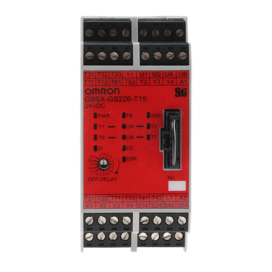
- Page 36 G9SX-GS Dimensions and Terminal Arrangement (Unit: mm) Safety Guard Switching Unit Terminal arrangement G9SX-GS226-T15-@ (6) (See note 2.) Y1 M1 M2 UA UB Y2 Y3 Y4 A1 T31 T32 T33 Y1 M1 M2 UA UB T12 T61 T62 Y2 Y3 Y4 A1 G9SX-GS226-T15 24VDC...
- Page 37 G9SX-GS Application Examples Highest achievable PL/ Model Stop category Reset safety category Emergency Stop Switch A165E/A22E Flexible Safety Unit G9SX-BC202 Emergency Stop: Manual PLe/4 equivalent M1, M2: 0 Safety Light Curtain F3SJ-B/F3SJ-E/F3SJ-A Safety Light Curtain: Auto Flexible Safety Unit G9SX-GS226-T15 Note: The above PL is only the evaluation result of the example.
- Page 38 G9SX-GS Timing Chart 1 G9SX-BC202 (Unit1) Emergency stop switch S1 Reset switch S2 Unit 1 S14, S24 KM1, KM2 NO contact Unit 1 Logical AND output L1 G9SX-GS226-T15 (Unit 2) Unit 2 Logical AND input T41 Safety Light Curtain 1 control output (monitoring the robot: Input A) Safety Light Curtain 2 control output (monitoring the operator: Input B)
- Page 39 G9SX-GS Highest achievable PL/ Model Stop category Reset safety category Emergency Stop Switch A165E/A22E Flexible Safety Unit G9SX-BC202 Safety Limit Switch D4B-N/D4N/D4F PLe/4 equivalent M1, M2: 0 Manual Guard Lock Safety-door Switch D4NS/D4GS-N/D4BS Safety Key Selector Switch A22TK Flexible Safety Unit G9SX-GS226-T15 Note: The above PL is only the evaluation result of the example.
- Page 40 G9SX-GS Feedback loop Application Examples Emergency Safety Limit Switch stop switch +24 V Open T12 T21 T22 T31 T32 T33 Y1 G9SX-BC202 (Unit 1) +24 V Control circuit Mode selector Safety Door Switch L1 L2 X1 X2 Emergency KM1 KM2 Stop Switch PLC etc.
- Page 41 G9SX-GS Timing Chart 2 G9SX-BC202 (Unit 1) (10) Emergency stop switch S1 Reset switch S2 Unit 1 S14, S24 Unit 1 Logical AND output L1 KM1, KM2 NO contact G9SX-GS226-T15 (Unit 2) Unit 2 Logical AND input T41 Limit switch S3 Safety limit switch S4 Safety Door Switch S5 Safety limit switch S6...
- Page 42 G9SX-GS Highest achievable PL/ Model Stop category Reset safety category Emergency Stop Switch A165E/A22E Flexible Safety Unit G9SX-BC202 Safety Limit Switch D4B-N/D4N/D4F PLe/4 equivalent Guard Lock Safety-door Switch D4NS/D4GS-N/D4BS M1, M2, M3: 0 Manual Safety Key Selector Switch A22TK Flexible Safety Unit G9SX-GS226-T15 Flexible Safety Unit G9SX-AD322-T15 Note: The above PL is only the evaluation result of the example.
- Page 43 G9SX-GS Feedback loop Application Examples Safety Limit Switch Emergency Mode selector stop switch Guard 1 +24 V Open T12 T21 T22 T31 T32 T33 Y1 G9SX-BC202 (Unit 1) Control circuit +24 V Emergency Stop Switch Guard 2 L1 L2 X1 X2 KM1 KM2 PLC etc.
- Page 44 G9SX-GS Timing Chart 3 G9SX-BC202 (Unit1) (10) Emergency stop switch S1 Reset switch S2 Unit 1 S14, S24 Unit 1 Logical AND output L1 KM1, KM2, NO contact G9SX-GS226-T15 (Unit2) Unit 2 Logical AND input T41 Limit switch S3 Safety limit switch S4 Safety Door Switch S5 Safety limit switch S6 Reset switch S8...
- Page 45 G9SX/G9SX-GS Safety Precautions Be sure to read the Common Precautions for Safety Warning at the following URL: http://www.ia.omron.com/. Indication and Meaning for Safe Use <G9SX-GS@> Indicates a potentially hazardous situation Serious injury may possibly occur due to loss of safety functions.
- Page 46 (area A) standard ISO K2: Maximum approach speed of a machine to 12. OMRON shall not be responsible for conformity with any safety the detection zone (area A) 13855 standards regarding to customer's entire system.
- Page 47 G9SX/G9SX-GS <G9SX-GS@> 5. Wiring (1) G9SX 1. Be sure to correctly connect safety input devices to safety input A • Wire the G9SX as described below. and safety input B to ensure proper operation of the safety functions. Solid wire 0.2 to 2.5 mm (AWG24 to AWG12) 2.
- Page 48 1. Use a mode selector that has an SPST-NO + SPST-NC contact function, such as Safety Sensors, apply 24 VDC to Y1 or Y2. form (e.g., OMRON’s A22K-@-11-@@). 6. Be sure to connect A2 to ground. 7. When using a G9SX-EX@-@ Expansion Unit, connect fuses with a current rating of 3.15 A maximum to the safety relay outputs to...
- Page 49 (a) Exclusive Warranty. Omron’s exclusive warranty is that the Products will be free from defects in materials and workmanship for a period of twelve months from the date of sale by Omron (or such other period expressed in writing by Omron). Omron disclaims all other warranties, express or implied.
Need help?
Do you have a question about the G9SX Series and is the answer not in the manual?
Questions and answers