Supermicro SSE-G24-TG4 User Manual
1/10 and 10-gigabit layer 2/3
1/10-gigabit ethernet switch, 1/10-gigabit ethernet switch, 10/40-gigabit ethernet switch, 10/40-gigabit ethernet switch, 10/40-gigabit ethernet switch
Hide thumbs
Also See for SSE-G24-TG4:
- User manual (268 pages) ,
- Configuration manual (34 pages) ,
- Stacking manual (16 pages)
Table of Contents
Advertisement
Quick Links
Advertisement
Table of Contents

Subscribe to Our Youtube Channel
Related Manuals for Supermicro SSE-G24-TG4


Summary of Contents for Supermicro SSE-G24-TG4
- Page 1 1/10 and 10-Gigabit Layer 2/3 Ethernet Switches SSE-G24-TG4 SSE-G48-TG4 1/10-Gigabit Ethernet Switch 1/10-Gigabit Ethernet Switch SSE-X24S/R 10/40-Gigabit Ethernet Switch SSE-X3348S/R 10/40-Gigabit Ethernet Switch SSE-X3348T/R 10/40-Gigabit Ethernet Switch User’s Manual Revison 1.1d...
- Page 2 This product, including software and documentation, is the property of Supermicro and/or its licensors, and is supplied only under a license. Any use or reproduction of this product is not allowed, except as expressly permitted by the terms of said license.
-
Page 3: Table Of Contents
Web-based Management Utility .............. 3-1 Command Line..................3-2 Firmware ....................3-3 Firmware Upgrading Procedures ............3-3 Firmware Failure Recovery Steps............3-6 Chapter 4 Ports and Indicators ............ 4-1 4-1 SSE-G24-TG4 Ports and Indicators ..........4-1 4-2 SSE-G48-TG4 Ports and Indicators ..........4-2... - Page 4 1/10 and 10-Gigabit Layer 2/3 Ethernet Switches User’s Manual 4-3 SSE-X24S/R Ports and Indicators ..........4-3 4-4 SSE-X3348S/R Ports and Indicators ..........4-4 4-5 SSE-X3348T/R Ports and Indicators ..........4-5 4-6 Ports ....................4-6 RJ45 Compatible Port................4-6 Combo Ports ................... 4-6 10-Gb/s Port Module Bays..............
- Page 5 Table of Contents Syslog ....................5-24 ACL ....................... 5-25 MAC ACL ................... 5-26 IP Standard ACL................. 5-27 IP Extended ACL................5-28 WEB Settings..................5-30 SNMP....................5-31 Community ..................5-33 Group ....................5-34 Group Access..................5-35 View ....................5-36 Target Address ................... 5-37 Target Parameter ................
- Page 6 1/10 and 10-Gigabit Layer 2/3 Ethernet Switches User’s Manual Port Manager ..................5-65 Basic Settings ..................5-66 Port Monitoring................... 5-67 Port Control ..................5-68 Storm Control/Rate Limiting ............... 5-69 Protected Ports .................. 5-70 VLAN..................... 5-71 Basic Settings ..................5-71 Port Settings..................5-72 Static VLANs ..................
- Page 7 Table of Contents Port Settings..................5-102 Timers ....................5-103 Local AS ................... 5-105 Filters ....................5-106 Unicast Filters .................. 5-106 Multicast Filters ................5-107 Link Tracking..................5-108 Loop Protect..................5-109 5-6 Layer 3 Management ..............5-110 IP......................5-111 VLAN Interface................. 5-111 IPv4 AddrConf ..................
- Page 8 1/10 and 10-Gigabit Layer 2/3 Ethernet Switches User’s Manual Basic Settings .................. 5-135 Area....................5-136 Interface ................... 5-137 Virtual Interface ................5-139 Neighbor................... 5-140 RRD Route..................5-141 Aggregation..................5-142 AsExtAggregation ................5-143 OSPF V3..................... 5-144 Basic Settings .................. 5-145 Interface ................... 5-146 Area....................
- Page 9 Table of Contents Router Ports ..................5-174 Group Information ................5-175 Dynamic Multicast................5-176 Dynamic Multicast ................5-176 Port Settings..................5-177 IGMP....................5-178 Basic Settings .................. 5-178 Interface Configuration..............5-179 Group Information ................5-180 Source Information................5-181 PIM...................... 5-182 Basic Settings .................. 5-182 Component..................
- Page 10 1/10 and 10-Gigabit Layer 2/3 Ethernet Switches User’s Manual Information ..................5-211 Port Statistics ................... 5-212 MSTP Statistics................... 5-213 MSTP Information ................5-213 CIST Port Statistics ................5-214 MSTI Port Statistics................5-216 Link Aggregation (LA) ................. 5-217 Port LACP Stats ................5-217 Neighbor Stats .................
- Page 11 IGMP....................5-245 PIM...................... 5-246 Interface Stats .................. 5-247 Neighbor Stats ................. 5-248 BSR Info................... 5-249 RP Set Info..................5-250 Mroute Info ..................5-251 DVMRP ....................5-252 Routes....................5-252 Multicast Routes................5-253 Prune Forward ................. 5-254 Appendix A Rack Installation ............A-1 A-1 Overview ....................A-1 A-2 Unpacking the System...
- Page 12 1/10 and 10-Gigabit Layer 2/3 Ethernet Switches User’s Manual Notes...
- Page 13 This manual is written for professional system integrators, Information Technology professionals, service personnel and technicians. It provides information for the installation and use of Supermicro's Layer 2/3 1/10 and 10-Gigabit Ethernet switches. Installation and maintenance should be performed by experienced professionals only.
- Page 14 1/10 and 10-Gigabit Layer 2/3 Ethernet Switches User’s Manual Notes...
-
Page 15: Chapter 1 Introduction
Chapter 1 Introduction Introduction This document is designed to provide Supermicro Switch users with the information required to configure the basic functionalities on the switch through the Web graphical user interface (GUI). Supermicro Switch products can be configured through Web browsers like Internet Explorer or Mozilla Firefox. -
Page 16: Product Checklist Of Typical Components
NOTE: The mounting ears can secure an SSE-X24S/R or SSE-X3348S/R switch to a rack, but will not reliably support the full weight of the switch for an extended period of time. Please use Supermicro mounting rails (CSE-PT52L) for full support of the switch in a rack installation (see Appendix A for details). -
Page 17: Features
440 x 473 x 44 mm (17.3 x 18.62 x 1.73 inch) for the SSE-X3348S/R • Weight: 5.6 kg (12.4 lbs) SSE-G24-TG4, 6.2 kg (13.7 lbs) SSE-G48-TG4, 7.58 kg (16.7 lbs) SSE-X24S/R, 8.2 kg (18.1 lbs) SSE-X3348S/R, or 9.2 kg (20.3 lbs) -
Page 18: Contacting Supermicro
Address: Super Micro Computer, Inc. 980 Rock Ave. San Jose, CA 95131 U.S.A. Tel: +1 (408) 503-8000 Fax: +1 (408) 503-8008 marketing@supermicro.com (General Information) Email: support@supermicro.com (Technical Support) Web Site: www.supermicro.com Europe Address: Super Micro Computer B.V. Het Sterrenbeeld 28, 5215 ML ‘s-Hertogenbosch, The Netherlands... -
Page 19: Chapter 2 Standardized Warning Statements
The following statements are industry standard warnings, provided to warn the user of situations which have the potential for bodily injury. Should you have questions or experience difficulty, contact Supermicro's Technical Support department for assistance. Only certified technicians should attempt to install or configure components. - Page 20 1/10 and 10-Gigabit Layer 2/3 Ethernet Switches User’s Manual Warnung WICHTIGE SICHERHEITSHINWEISE Dieses Warnsymbol bedeutet Gefahr. Sie befinden sich in einer Situation, die zu Verletzungen führen kann. Machen Sie sich vor der Arbeit mit Geräten mit den Gefahren elektrischer Schaltungen und den üblichen Verfahren zur Vorbeugung vor Unfällen vertraut.
-
Page 21: Installation Instructions
Chapter 2: Standardized Warning Statements 이 경고 기호는 위험이 있음을 알려 줍니다 . 작업자의 신체에 부상을 야기 할 수 있는 상태에 있게 됩니다 . 모든 장비에 대한 작업을 수행하기 전에 전기회로와 관련된 위험 요소들을 확인하시고 사전에 사고를 방지할 수 있도록 표준 작업절차를 준수해 주시기 바랍니다... -
Page 22: Circuit Breaker
1/10 and 10-Gigabit Layer 2/3 Ethernet Switches User’s Manual ﻣﺼﺪر ﻟﻠﻄﺎﻗﺔ اﻟﻨﻈﺎم إﻟﻰ ﻗﺒﻞ ﺗﻮﺻﯿﻞ ﺘﺮﻛﯿﺐ اﻗﺮ إرﺷﺎدات اﻟ 시스템을 전원에 연결하기 전에 설치 안내를 읽어주십시오 . Waarschuwing Raadpleeg de installatie-instructies voordat u het systeem op de voedingsbron aansluit. Circuit Breaker Warning! This product relies on the building's installation for short-circuit (overcurrent) protection. -
Page 23: Power Disconnection Warning
Chapter 2: Standardized Warning Statements ﻓﻲ اﻟﺘﻲ ﺗﻢ ﺗﺜﺒﯿﺘﮭﺎ ﻣﻦ اﻟﺪواﺋﺮاﻟﻘﺼﯿﺮة اﻟﺤﻤﺎﯾﺔ ﻣﻌﺪات ﯾﻌﺘﻤﺪ ﻋﻠﻰ ھﺬا اﻟﻤﻨﺘﺞ اﻟﻤﺒﻨﻰ أﻛﺜﺮ ﻣﻦ ﻟﯿﺲ ﻮﻗﺎﺋﻲ اﻟ اﻟﺠﮭﺎز ﺗﻘﯿﯿﻢ أن ﺗﺄﻛﺪ ﻣﻦ 20A, 250V 경고 ! 이 제품은 전원의 단락 ( 과전류 ) 방지에 대해서 전적으로 건물의 관련 설비에 의존합니 다... -
Page 24: Equipment Installation
1/10 and 10-Gigabit Layer 2/3 Ethernet Switches User’s Manual ¡Advertencia! El sistema debe ser disconnected de todas las fuentes de energía y del cable eléctrico quitado de los módulos de fuente de alimentación antes de tener acceso el interior del chasis para instalar o para quitar componentes de sistema. -
Page 25: Restricted Area
Chapter 2: Standardized Warning Statements Warnung Das Installieren, Ersetzen oder Bedienen dieser Ausrüstung sollte nur geschultem, qualifiziertem Personal gestattet werden. ¡Advertencia! Solamente el personal calificado debe instalar, reemplazar o utilizar este equipo. Attention Il est vivement recommandé de confier l'installation, le remplacement et la maintenance de ces équipements à... - Page 26 1/10 and 10-Gigabit Layer 2/3 Ethernet Switches User’s Manual Warnung Diese Einheit ist zur Installation in Bereichen mit beschränktem Zutritt vorgesehen. Der Zutritt zu derartigen Bereichen ist nur mit einem Spezialwerkzeug, Schloss und Schlüssel oder einer sonstigen Sicherheitsvorkehrung möglich. ¡Advertencia! Esta unidad ha sido diseñada para instalación en áreas de acceso restringido.
-
Page 27: Battery Handling
Chapter 2: Standardized Warning Statements Battery Handling Warning! There is the danger of explosion if the battery is replaced incorrectly. Replace the battery only with the same or equivalent type recommended by the manufacturer. Dispose of used batteries according to the manufacturer's instructions. 電池の取り扱い... -
Page 28: Redundant Power Supplies
1/10 and 10-Gigabit Layer 2/3 Ethernet Switches User’s Manual 배터리가 올바르게 교체되지 않으면 폭발의 위험이 있습니다 . 기존 배터리와 동일하거 나 제조사에서 권장하는 동등한 종류의 배터리로만 교체해야 합니다 . 제조사의 안내에 따라 사용된 배터리를 처리하여 주십시오 . Waarschuwing Er is ontploffingsgevaar indien de batterij verkeerd vervangen wordt. Vervang de batterij slechts met hetzelfde of een equivalent type die door de fabrikant aanbevolen wordt. -
Page 29: Backplane Voltage
Chapter 2: Standardized Warning Statements اﻣﺪاد اﻟﻄﺎﻗﺔ ﺑﻮﺣﺪات ﻋﺪة اﺗﺼﺎﻻت ﺠﮭﺎز اﻟ ﯾﻜﻮن ﻟﮭﺬا ﻗﺪ اﻟﻜﮭﺮﺑﺎء ﻋﻦ ﻮﺣﺪة اﻟ ﻟﻌﺰل ﻛﺎﻓﺔ اﻻﺗﺼﺎﻻت ﯾﺠﺐ إزاﻟﺔ 경고 ! 이 장치에는 한 개 이상의 전원 공급 단자가 연결되어 있을 수 있습니다 . 이 장치에 전 원을... -
Page 30: Comply With Local And National Electrical Codes
1/10 and 10-Gigabit Layer 2/3 Ethernet Switches User’s Manual اﻟﻠﻮﺣﺔ أواﻟﻄﺎﻗﺔ اﻟﻤﻮﺟﻮدة ﻋﻠﻰ اﻟﺘﯿﺎر اﻟﻜﮭﺮﺑﺎﺋﻲ ﻣﻦ ﺧﻄﺮ ھﻨﺎك ھﺬا اﻟﺠﮭﺎز ﺧﺪﻣﺔ ﻛﻦ ﺣﺬرا ﻋﻨﺪ ﯾﻌﻤﻞ اﻟﻨﻈﺎم ﻋﻨﺪﻣﺎ ﯾﻜﻮن 경고 ! 시스템이 동작 중일 때 후면판 (Backplane) 에는 위험한 전압이나 에너지가 발생 합니 다... -
Page 31: Product Disposal
Chapter 2: Standardized Warning Statements 경고 ! 현 지역 및 국가의 전기 규정에 따라 장비를 설치해야 합니다 . Waarschuwing Bij installatie van de apparatuur moet worden voldaan aan de lokale en nationale elektriciteitsvoorschriften. Product Disposal Warning! Ultimate disposal of this product should be handled according to all national laws and regulations. -
Page 32: Hot Swap Fan Warning
1/10 and 10-Gigabit Layer 2/3 Ethernet Switches User’s Manual 경고 ! 이 제품은 해당 국가의 관련 법규 및 규정에 따라 폐기되어야 합니다 . Waarschuwing De uiteindelijke verwijdering van dit product dient te geschieden in overeenstemming met alle nationale wetten en reglementen. Hot Swap Fan Warning Warning! The fans might still be turning when you remove the fan assembly from the... -
Page 33: Power Cable And Ac Adapter
Electrical Appliance and Material Safety Law prohibits the use of UL or CSA -certified cables (that have UL/CSA shown on the code) for any other electrical devices than products designated by Supermicro only. 電源コードと AC アダプター... - Page 34 Fehlfunktion oder ein Brand entstehen. Elektrische Geräte und Material Safety Law verbietet die Verwendung von UL-oder CSA-zertifizierte Kabel, UL oder CSA auf der Code für alle anderen elektrischen Geräte als Produkte von Supermicro nur bezeichnet gezeigt haben.
- Page 35 Het gebruik van andere kabels en adapters kan leiden tot een storing of een brand. Elektrisch apparaat en veiligheidsinformatiebladen wet verbiedt het gebruik van UL of CSA gecertificeerde kabels die UL of CSA die op de code voor andere elektrische apparaten dan de producten die door Supermicro alleen. 2-17...
- Page 36 1/10 and 10-Gigabit Layer 2/3 Ethernet Switches User’s Manual Notes 2-18...
-
Page 37: Chapter 3 Installation And Setup
1. Carefully unpack the switch from its shipping container and verify that all parts are present. 2. Install the 10-Gb/s add-on module(s) in the rear (SSE-G24-TG4 and SSE-G48-TG4 only). 3. Install the mounting ears onto the side of the switch using a screwdriver. -
Page 38: Command Line
1/10 and 10-Gigabit Layer 2/3 Ethernet Switches Command Line Configuring the switch can be done using a command line via telnet or by using the serial console interface. Accessing CLI through Telnet To access the command line via telnet, follow the below steps. 1. -
Page 39: Firmware
Chapter 3: Installation and Setup Firmware The firmware for Layer 2/3 1/10 and 10-Gigabit Ethernet switches resides on a chip on the PCB. The switch has internal flash memory in two areas to hold two firmware images. The flash area used for the normal firmware image is referred to as the normal area. The other flash area, referred to as the fallback area, is used to store the firmware image for fallback purpose in case of a failure to boot from the normal area. - Page 40 1/10 and 10-Gigabit Layer 2/3 Ethernet Switches Booting using a Fallback Firmware Image Use the procedure below to boot using a fallback firmware image. 1. Reboot the switch by power cycling the switch power. 2. During reboot, press any key when it displays the below text (as shown in Figure 3-1).
- Page 41 Chapter 3: Installation and Setup Use the "H" option to set hardware information by typing the character H. This will display the hardware information that can be changed as shown in Figure 3-2. Figure 3-2. Setting Hardware Information 4. To choose the boot from a fallback image, type the command: rflag=1 5.
-
Page 42: Firmware Failure Recovery Steps
1/10 and 10-Gigabit Layer 2/3 Ethernet Switches 3. Login to the Switch CLI either through Telnet or a serial console port. 4. Type the below command to upgrade the firmware in the normal area: firmware upgrade tftp://<ip-address>/<filename> flash:fallbackl Here <ip-address> is the IP address of the TFTP server and <filename> is the name of the firmware image file. - Page 43 Chapter 3: Installation and Setup For example tftpaddr=192.168.2.100 9. Configure the gateway address to reach the TFTP server using the following command if the TFTP server is in a different network: gateway=<gateway IP> For example gateway=192.168.2.100 10. Configure the firmware image file name using the following command: ramdiskname=<filename>...
- Page 44 1/10 and 10-Gigabit Layer 2/3 Ethernet Switches Notes...
-
Page 45: Chapter 4 Ports And Indicators
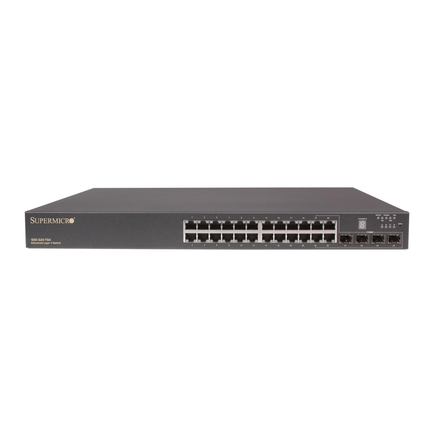
10-Gigabit Ethernet switches. SSE-G24-TG4 Ports and Indicators Figure 4-1. SSE-G24-TG4 Ports and Indicators Front View Rear View Table 4-1. SSE-G24-TG4 Switch Module Ports and Indicators Item Description RJ45 10/100/1000 Ethernet ports (24) SFP Combo Ports (4) LEDs and Stacking Indicator ID... -
Page 46: Sse-G48-Tg4 Ports And Indicators
1/10 and 10-Gigabit Layer 2/3 Ethernet Switches SSE-G48-TG4 Ports and Indicators Figure 4-2. SSE-G48-TG4 Ports and Indicators Front View Rear View Table 4-2. SSE-G24-TG4 Switch Module Ports and Indicators Item Description RJ45 10/100/1000 Ethernet ports (48) SFP Combo Ports (4) -
Page 47: Sse-X24S/R Ports And Indicators
Chapter 4: Ports and Indicators SSE-X24S/R Ports and Indicators Figure 4-3. SSE-X24S/R Ports and Indicators Table 4-3. SSE-X24S/R Switch Module Ports and Indicators Item Description System Status Indicator Fan Status Indicator Status Indicator – Power Supply 1 Status Indicator – Power Supply 2 1-Gbps port (Line or console) 10-Gbps Ethernet Ports –... -
Page 48: Sse-X3348S/R Ports And Indicators
1/10 and 10-Gigabit Layer 2/3 Ethernet Switches SSE-X3348S/R Ports and Indicators Figure 4-4. SSE-X3348S/R Ports and Indicators Table 4-4. SSE-X3348S/R Switch Module Ports and Indicators Item Description Status indicators for: System, Fan, Power Supply 1 and Power Supply 2 1-Gbps ports (Line or console) 10-Gbps Ethernet Ports - SFP+ connectors 40-Gbps Ethernet ports –... -
Page 49: Sse-X3348T/R Ports And Indicators
Chapter 4: Ports and Indicators SSE-X3348T/R Ports and Indicators Figure 4-5. SSE-X3348T/R Ports and Indicators Table 4-5. SSE-X3348T/R Switch Module Ports and Indicators Item Description Status indicators for: System, Fan, Power Supply 1 and Power Supply 2 1-Gbps ports (Line or console) 10-Gbps Ethernet Ports - RJ45 connectors 40-Gbps Ethernet ports –... -
Page 50: Ports
Both Layer 2/3 1/10-Gigabit Ethernet switches contain several front mounted ports in common. RJ45 Compatible Port These 24 (SSE-G24-TG4) or 48 (SSE-G48-TG4) 1-Gb/s duplex ports each accept an RJ45 compatible cable. Combo Ports Each of the four SFP 1-Gb/s combo ports can hold a module for a downlinking fiber connector. -
Page 51: Serial Ports
AOM-SSE-X2C module with two CX4 copper interface ports for connections up to 12 meters in distance. NOTE: You must use a Supermicro CX4 cable if you are using one or more of these ports for stacking. You may use the Supermicro CBL-0474L for 1M connections or the CBL-0389L-01 for 3M connections. - Page 52 1/10 and 10-Gigabit Layer 2/3 Ethernet Switches Notes...
-
Page 53: Chapter 5 Web Based Management Utility
Port Number Ext */* – This is for an external port. Overview The Supermicro switch utility for Layer 2/3 1/10 and 10-Gigabit Ethernet switches provides a web-based interface for managing Layer 2 and Layer 3 switching at wire speed for constructing a switched/routed network. This interface provides both a bridging functionality and advanced features such as link aggregation, Dynamic VLAN/ Dynamic Multicast, IGMP Snooping and Network Access Control. -
Page 54: Login
ETTINGS in the System Management section. For the SSE-G48-TG4 and SSE-G24-TG4 switches you can connect to any of the front panel 1G ports or back panel 10G ports to manage the switch with the default management IP. These switches will create VLAN 1 by default with this IP address, including all 1G and 10G ports. -
Page 55: Home Page
(Figure 5-2) contains links and menus for going to all other control pages in the Supermicro Switch web-based interface utility. A list of controls for this page is shown in Table 5-1. The basic page structure of the H page is duplicated for all subsequent sub-pages of the Supermicro Switch web-based interface utility. - Page 56 The information in this page presents a brief overview of the switch web-based management utility. See Figure 5-3, Figure 5-4 Figure 5-5 for different views of the Home page for each of Supermico’s 10-Gb/s switches. Figure 5-3. SSE-G24-TG4 Home Page...
- Page 57 Chapter 5: Web Based Management Utility Figure 5-4. SSE-G48-TG4 Home Page Figure 5-5. SSE-X24S/R Home Page...
- Page 58 1/10 and 10-Gigabit Layer 2/3 Ethernet Switches User’s Manual Figure 5-6. SSE-X3348S/R Home Page Figure 6. SSE-X3348T/R Home Page...
-
Page 59: Top Page Links
• Support – Click this link to get technical support for Supermicro Products. • Help – Click on this link to open a context specific help page that covers all the items on the page being viewed. -
Page 60: Middle Configuration Link Table
1/10 and 10-Gigabit Layer 2/3 Ethernet Switches User’s Manual • System Management - System based configurations • Layer 2 Management - Layer 2 Protocols including VLAN, RSTP, MSTP, … • Layer 3 Management - Layer 3 Protocols including - IP, RIP, OSPF, …. •... -
Page 61: System Management Page
Chapter 5: Web Based Management Utility System Management Page Figure 5-1. System Management Page The S page (Figure 5-1) contains the following links: YSTEM ANAGEMENT • System Settings • Management IP • File Management • Firmware Upgrade • Management Security •... -
Page 62: System Settings
SNMP engine. A restart of the switch SNMP Engine ID required if these values are changed. The factory default is 80.00.08.1c.04.46.53 Assigns a contact person's name with a 255-character input limit. The Device Contact factory default is http://www.supermicro.com/support. 5-10... - Page 63 Description This specifies the location of this switch using a 255-characters input limit. Device Location The factory default is Supermicro. This specifies the maximum transmission unit (MTU) size of IP packets System MTU sent on an interface. The valid range is between 1500 and 9210, while the default value is 1500.
-
Page 64: System Version
1/10 and 10-Gigabit Layer 2/3 Ethernet Switches User’s Manual System Version Figure 5-3. System Version Page Clicking the S tab brings up the S page (Figure 5-3). This YSTEM ERSION YSTEM ERSION page provides a table that displays system version information including the Switch ID, Hardware Version and Firmware Version for each switch. -
Page 65: Management Ip
Chapter 5: Web Based Management Utility Management IP Figure 5-4. Management IP Page Clicking the M IP tab brings up the M IP page (Figure 5-4). This ANAGEMENT ANAGEMENT page helps you to manage the IP address for the switch. This page allows configuration of the following settings: •... -
Page 66: File Management
1/10 and 10-Gigabit Layer 2/3 Ethernet Switches User’s Manual File Management Figure 5-5. File Management Page Clicking the F link brings up the F page (Figure 5-5). ANAGEMENT ANAGEMENT The F page helps you to manage the configuration files in the switch. ANAGEMENT This page provides three main features. -
Page 67: File Copy
Chapter 5: Web Based Management Utility File Copy You can copy a local file to or from a remote TFTP server. This feature is useful to create a backup of configuration files remotely, and also to download configuration files from remote computers to the switch. -
Page 68: Management Security
1/10 and 10-Gigabit Layer 2/3 Ethernet Switches User’s Manual Management Security The M link provides configuration for the following features: ANAGEMENT ECURITY • Management Security • User Accounts • Radius • TACACS+ • TACACS+ Servers • IP Auth Manager • •... -
Page 69: User Accounts
Chapter 5: Web Based Management Utility Table 5-3. Management Security Basic Settings Page Parameters Parameter Description The authentication modes supported are L , RADIUS and TACACS. The OCAL default option is L mode where the user name and password is OCAL Authentication mode authenticated using a local user data base. -
Page 70: Radius
1/10 and 10-Gigabit Layer 2/3 Ethernet Switches User’s Manual Clicking the L tab brings up the M OCAL SERS ANAGEMENT CCOUNT page (Figure 5-8). This page allows you to create or delete local user ONFIGURATION accounts. You need more than privilege Level_5 to view all pages and need more than privilege Level_10 for changing the configurations. -
Page 71: Tacacs
Chapter 5: Web Based Management Utility Table 5-4. RADIUS Server Configuration Page Parameters Parameter Description This parameter specifies the secret string, which is shared between the RADIUS Shared Secret Server and the RADIUS Client. This field contains a 255-characters input limit, and the factory default is blank. -
Page 72: Tacacs+ Servers
1/10 and 10-Gigabit Layer 2/3 Ethernet Switches User’s Manual Table 5-5. TACACS+ Global Settings Page Parameters Parameter Description Specifies the IP address of the active TACACS server. This server should have Active Server IP been already configured in the TACACS+ S page ERVER ONFIGURATION... -
Page 73: Ip Auth Manager
Chapter 5: Web Based Management Utility Table 5-6. TACACS+ Server Configuration Page Parameters Parameter Description The time for which the switch will wait for a response from the TACACS server Timeout before closing the connection is specified with this parameter. It is configurable in seconds, with the valid range is from 4 to 15 and the default as 5-seconds.. -
Page 74: Ssh
1/10 and 10-Gigabit Layer 2/3 Ethernet Switches User’s Manual Table 5-7. IP Authorized Manager Page Parameters Parameter Description This lists the port through which the manager can access this switch. Ports can Port List (Incoming) be comma separated or provided as a range (for example Gi0/1 or Ex0/1). The factory default is blank. -
Page 75: Ssl
Chapter 5: Web Based Management Utility Table 5-8. SSH Configuration Page Parameters Parameter Description The default for this parameter is 3DES-CBC. You can instead choose to Cipher configure it as 3DES-CBC or DES-CBC or both This parameter’s default is HMAC-SHA1. You can instead choose to configure it Authentication as HMAC-SHA1 or HMAC-MD5 or both. -
Page 76: Syslog
1/10 and 10-Gigabit Layer 2/3 Ethernet Switches User’s Manual 4. To generate an SSL certificate, the openssl application can be used. The sub-steps below can be executed in any Linux machine to generate SSL certificates. For other openssl implementations, refer to the openssl documentation to find the equivalent steps for them. -
Page 77: Acl
Chapter 5: Web Based Management Utility Clicking the L tab brings up the S page (Figure 5-15), OGGING YSLOG ONFIGURATION which allows you to configure logging parameters. The parameters for this page are shown in Table 5-9. Table 5-9. Syslog Configuration Page Parameters Parameter Description Syslog... - Page 78 1/10 and 10-Gigabit Layer 2/3 Ethernet Switches User’s Manual MAC ACL Figure 5-16. MAC ACL Configuration Page Clicking the M ACL tab brings up the M ACL C page (Figure 5-16), ONFIGURATION which displays the various parameters to configure the MAC Access List. The parameters for this page are shown in Table 5-10.
- Page 79 Chapter 5: Web Based Management Utility Table 5-10. MAC ACL Configuration Page Parameters (Continued) Parameter Description The priority of the L3 filter is used to decide which filter rule is applicable when the packet matches with more than one set of filter rules. The higher value of Priority “Filter Priority”...
- Page 80 1/10 and 10-Gigabit Layer 2/3 Ethernet Switches User’s Manual Table 5-11. IP Standard ACL Configuration Page Parameters Parameter Description This specifies the unique ID for the access list. The valid range is between 1 and ACL Number 32768. The factory default is blank. This specifies the action to be taken for the access list.
- Page 81 Chapter 5: Web Based Management Utility Table 5-12. IP Extended ACL Configuration Page Parameters Parameter Description This specifies the unique ID for the access list. The valid range is between 1 to ACL Number 32768. The factory default is blank. Subnet Mask This specifies the Address Mask corresponding to the IP Address.
-
Page 82: Web Settings
1/10 and 10-Gigabit Layer 2/3 Ethernet Switches User’s Manual WEB Settings Figure 5-19. Web GUI Settings Page Clicking the W link brings up the W GUI S page (Figure 5-19), ETTINGS ETTINGS which displays all basic Web GUI settings. The parameters for this page are shown in Table 5-13. -
Page 83: Snmp
Chapter 5: Web Based Management Utility SNMP Figure 5-20. SNMP Agent Control Settings Page Clicking the SNMP link brings up the SNMP A page GENT ONTROL ETTINGS (Figure 5-20). SMIS supports the SNMP Agent or SNMP AgentX Sub-agent. The SNMP Agent or AgentX Sub-agent can be enabled or both can be disabled. The SNMP Agent provides the following sub-page configurations shown in the table below. - Page 84 1/10 and 10-Gigabit Layer 2/3 Ethernet Switches User’s Manual Table 5-14. SNMP Agent Configuration Pages (Continued) Configuration Description Page This setting allows you to configure SNMP target parameters including Target Parameter , MP M and S ARAMETER ODEL ECURITY ODEL EVEL TORAGE This setting allows you to configure SNMP security including user name,...
-
Page 85: Community
Chapter 5: Web Based Management Utility Community Figure 5-21. SNMP Community Settings Page Clicking the C tab brings up the SNMP C page OMMUNITY OMMUNITY ETTINGS (Figure 5-21), which allows you to add SNMP managers or remove existing managers.. The parameters for this page are shown in Table 5-15. -
Page 86: Group
1/10 and 10-Gigabit Layer 2/3 Ethernet Switches User’s Manual Group Figure 5-22. SNMP Group Settings Page Clicking the G tab brings up the SNMP G page (Figure 5-22). This ROUP ROUP ETTINGS page helps you map a combination of the S and the S into ECURITY... -
Page 87: Group Access
Chapter 5: Web Based Management Utility Group Access Figure 5-23. SNMP Group Access Settings Page Clicking the G tab brings up the SNMP G page ROUP CCESS ROUP CCESS ETTINGS (Figure 5-23), which displays the access rights of groups. Each entry is indexed by a , a Context Prefix, a S and a S . -
Page 88: View
1/10 and 10-Gigabit Layer 2/3 Ethernet Switches User’s Manual Table 5-17. SNMP Group Access Settings Page Parameters (Continued) Parameter Description Use this parameter to specify whether the S is volatile or TORAGE Storage Type non-volatile. Use this parameter to configure an SNMP context name that identifies this Context group. -
Page 89: Target Address
Chapter 5: Web Based Management Utility Table 5-18. SNMP View Tree Settings Page Parameters (Continued) Parameter Description View Type This parameter specifies whether a View Type is Included or Excluded. Use this parameter to specify whether the Storage Type is volatile or Storage Type non-volatile. -
Page 90: Target Parameter
1/10 and 10-Gigabit Layer 2/3 Ethernet Switches User’s Manual Table 5-19. SNMP Target Address Settings Page Parameters (Continued) Parameter Description Param contains SNMP parameters to be used when generating messages to be Param sent to a transport address. Use this parameter to specify whether the Storage Type is volatile or Storage Type non-volatile. -
Page 91: User
Chapter 5: Web Based Management Utility Table 5-20. SNMP Target Parameter Settings Page Parameters (Continued) Parameter Description Security Level specifies the level of security used when generating SNMP Security Level messages. Storage Type Storage Type can be configured as Volatile or Non-Volatile. Engine ID This parameter displays the SNMP Engine ID. -
Page 92: Trap Manager
1/10 and 10-Gigabit Layer 2/3 Ethernet Switches User’s Manual Table 5-21. SNMP Security Settings Page Parameters (Continued) Parameter Description Privacy Key is an indication of whether or not messages sent on behalf of this Privacy Key user to/from the SNMP are protected from disclosure. Storage Type Storage Type can be configured as Volatile or Non-Volatile. -
Page 93: Snmp Agentx
Chapter 5: Web Based Management Utility SNMP AgentX Figure 5-29. SNMP AgentX Subagent Settings Page Clicking the A X link brings up the SNMP A page GENT GENT UBAGENT ETTINGS (Figure 5-29), which allows you to configure SNMP Agentx sub-agent parameters. The parameters for this page are shown in Table 5-23. -
Page 94: Rmon
1/10 and 10-Gigabit Layer 2/3 Ethernet Switches User’s Manual RMON The following pages can be used to set RMON (Remote Monitoring) features and settings: • Basic Settings • Events • Alarm • Ethernet Statistics • History Basic Settings Figure 5-30. RMON Basic Settings Page Clicking the B tab brings up the RMON B page... -
Page 95: Events
Chapter 5: Web Based Management Utility Events Figure 5-31. Event Configuration Settings Page Clicking the E tab brings up the E page (Figure 5-31), which VENTS VENT ONFIGURATIONS configures RMON events. The parameters for this page are shown in Table 5-24. -
Page 96: Alarm
1/10 and 10-Gigabit Layer 2/3 Ethernet Switches User’s Manual Alarm Figure 5-32. RMON Alarm Configuration Page Clicking the A tab brings up the RMON A page (Figure 5-32), LARM LARM ONFIGURATION which configures RMON Alarm paramters. The parameters for this page are shown in Table 5-25. -
Page 97: Ethernet Statistics
Chapter 5: Web Based Management Utility Table 5-25. RMON Alarm Configuration Page Parameters (Continued) Parameter Description Indicates the index of the event to be raised when the F ALLING THRESHOLD Falling Event Index reached. This value must be in the range from 0 to 65535. Owner Specifies the owner of the alarm. - Page 98 1/10 and 10-Gigabit Layer 2/3 Ethernet Switches User’s Manual Table 5-26. Ethernet Statistics Configuration Page Parameters (Continued) Parameter Description This parameter specifies the total number of multicast packets received from the Multicast Packets network. Owner This parameter specifies the owner string. Undersized Packets Displays the number of undersized packets received from the network.
-
Page 99: History
Chapter 5: Web Based Management Utility History Figure 5-34. History Control Configuration Page Clicking the H tab brings up the H page ISTORY ISTORY ONTROL ONFIGURATION (Figure 5-34), which configures RMON history configuration parameters. The parameters for this page are shown in Table 5-27. -
Page 100: Qos
1/10 and 10-Gigabit Layer 2/3 Ethernet Switches User’s Manual The QoS link of the System page opens the QoS Basic Settings page. This page allows you to configure QoS through following pages: • Basic Settings • Classmap • Policymap Basic Settings Figure 5-35. -
Page 101: Classmap
Chapter 5: Web Based Management Utility Classmap Figure 5-36. QOS Classmap Settings Page Clicking the C tab brings up the QOS C page (Figure 5-36), LASSMAP LASSMAP ETTINGS which is used to classify the stream of traffic. The parameters for this page are shown in Table 5-29. -
Page 102: Policymap
1/10 and 10-Gigabit Layer 2/3 Ethernet Switches User’s Manual Policymap Figure 5-37. QOS Policymap Settings Page Clicking the P tab brings up the QOS P page (Figure 5-37), OLICYMAP OLICYMAP ETTINGS which is used to specify action for a specified classmap. The parameters for this page are shown in Table 5-30. -
Page 103: Vlan Cos
Chapter 5: Web Based Management Utility VLAN COS The VLAN COS page opens the VLAN Class of Service (COS) Que Mapping Global Settings page. This page allows you to configure VLAN COS through the following pages: • COS Queue Mapping •... -
Page 104: Queue Configuration
1/10 and 10-Gigabit Layer 2/3 Ethernet Switches User’s Manual Queue Configuration Figure 5-39. VLAN Class of Service (COS) Queue Scheduling and Bandwidth Control Clicking the Q tab brings up the VLAN C (COS) UEUE ONFIGURATION LASS OF ERVICE page (Figure 5-38), which configures VLAN CHEDULING AND ANDWIDTH... -
Page 105: Time Management
Chapter 5: Web Based Management Utility Table 5-32. VLAN COS Queue Scheduling and Bandwidth Control Page Parameters Parameter Description Reset to Defaults Sets the default values for all the configuration in this page. To apply the same configuration on multiple ports, provide the port list on this Apply On Port Lists field and click on A . - Page 106 1/10 and 10-Gigabit Layer 2/3 Ethernet Switches User’s Manual Table 5-33. NTP Settings Page Parameters (Continued) Parameter Description Receive Server The value for this parameter could be Broadcast or Unicast. To process the Update broadcast NTP updates from the server, choose the Broadcast option. Timezone Settings Hour Offset This parameter allows you to enter an hour offset from GMT for local time.
-
Page 107: Clock Settings
Time, and DD:MM::YYYY for the date. Stack The Supermicro Intelligent switch supports stacking of the SSE-G24-TG4 and SSE-G48-TG4 Supermicro switch units. Switch stacking is created by connecting switches in a daisy chain. One of the stacked switches is selected as a Master based on its configurations. - Page 108 MAC address is selected as the Master switch. Enabling Stacking By default, Supermicro switches act as stand-alone switches. This stand-alone default facilitates using 10G Ethernet ports as Extrement Ethernet ports for uplinks. When stacking is enabled the stacking ports are dedicated for stacking purposes.
-
Page 109: Stack Settings
Chapter 5: Web Based Management Utility Figure 5-42. Switch Diagram NOTE: In a stack only one switch can be configured as master. Otherwise the slave switches will not allow you to configure anything except stacking disabled. To login to slave switches, use a login name as "stackuser"... - Page 110 1/10 and 10-Gigabit Layer 2/3 Ethernet Switches User’s Manual Stack Settings Figure 5-43. Stack Configuration Page Clicking the S tab brings up the S page TACK ETTINGS TACK ONFIGURATION (Figure 5-43), which configures the stacking feature. The parameters for this page are shown in Table 5-35.
- Page 111 Chapter 5: Web Based Management Utility Stack Details Figure 5-44. Stack Details Page Clicking the S tab brings up the S page (Figure 5-44), which TACK ETAILS TACK ETAILS displays stacking details. The parameters for this page are shown in Table 5-36.
- Page 112 1/10 and 10-Gigabit Layer 2/3 Ethernet Switches User’s Manual Table 5-36. Stack Details Page Parameters (Continued) Parameter Description This parameter is used to specify the MAC address of the Slave switch. This Stack MAC MAC address is used to communicate between stack member switches. Switch State This parameter is used to specify the current status of the Slave switch.
-
Page 113: Stack Counters
Chapter 5: Web Based Management Utility Stack Counters Figure 5-46. Stack Counter Details Page Clicking the S tab brings up the S page TACK OUNTERS TACK OUNTERS ETAILS (Figure 5-46), which displays statistics for stacking ports. The parameters for this page are shown in Table 5-38. -
Page 114: Cx4 Cable Length
HC counter is 64-bit. CX4 Cable Length Stacking is supported with Supermicro CX-4 cables only. The CX-4 cable used for stacking should be no more than 3-meters in length, because stacking internally runs at 12-Gbps and therefore requires a more robust signal than longer cable lengths might provide reliably. -
Page 115: Layer 2 Management
Chapter 5: Web Based Management Utility This configuration is done on an individual port basis. Thus, you can use short for one port and long for the other port. Alternatively you might use both short or, if neither are for stacking, both can be long cables. Layer 2 Management Figure 5-48. -
Page 116: Layer 2 Basic Settings
1/10 and 10-Gigabit Layer 2/3 Ethernet Switches User’s Manual Layer 2 Basic Settings Figure 5-49. MAC Address Table Settings Page Clicking the L link brings up the MAC A AYER ASIC ETTINGS DDRESS ABLE ETTINGS page (Figure 5-49), which gives you the option to change MAC aging time. MAC address confirmation can be done with this time interval. -
Page 117: Port Manager
Chapter 5: Web Based Management Utility Port Manager The P link has links to the following web pages: ANAGER • Basic Settings • Port Monitoring • Port Control • Storm Control/Rate Limiting • Protected Ports NOTE: In all port based configuration pages, the port number group links are provided on the top. - Page 118 1/10 and 10-Gigabit Layer 2/3 Ethernet Switches User’s Manual Basic Settings Figure 5-50. Port Basic Settings Page Clicking the B tab brings up the P page (Figure 5-50), ASIC ETTINGS ASIC ETTINGS which allows you to configure port status and mode information. This page also helps configuring priority and MTU.
-
Page 119: Port Monitoring
Chapter 5: Web Based Management Utility Port Monitoring Figure 5-51. Port Monitoring Configuration Page Clicking the P tab brings up the P ONITORING ONITORING ONFIGURATION page (Figure 5-51), which allows you to enable or disbale monitoring on port interface. The parameters for this page are shown in Table 5-40. -
Page 120: Port Control
1/10 and 10-Gigabit Layer 2/3 Ethernet Switches User’s Manual Port Control Figure 5-52. Port Control Page Clicking the P tab brings up the P page (Figure 5-52), which ONTROL ONTROL allows you to change port parameters for ports that you select by clicking on the check box in front of them (or checking ALL to select all ports). -
Page 121: Storm Control/Rate Limiting
Chapter 5: Web Based Management Utility Storm Control/Rate Limiting Figure 5-53. Storm Control/Rate Limiting Page Clicking the S tab brings up the S TORM ONTROL IMITING TORM ONTROL page (Figure 5-53), which allows you to configure specific parameters of the IMITING port. -
Page 122: Protected Ports
1/10 and 10-Gigabit Layer 2/3 Ethernet Switches User’s Manual Table 5-42. Storm Control/Rate Limiting Page Parameters (Continued) Parameter Description Multicast Level This parameter allows you to specify the multicast packets per second. The following parameters are configurable for Egress Rate Limiting. Egress Port Rate This parameter allows you to specify the egress limit of packets per second. -
Page 123: Vlan
Chapter 5: Web Based Management Utility VLAN The VLAN link allows to configure the VLAN information. VLAN configuration information has been provided in the following pages: • Basic Settings • Port Settings • Static VLANs • Protocol Group • Port Protocol •... - Page 124 1/10 and 10-Gigabit Layer 2/3 Ethernet Switches User’s Manual Table 5-44. VLAN Basic Settings Page Parameters (Continued) Parameter Description MAC Based on All This parameter enables or disables the per Port MAC based classification. Ports This parameter enables or disables the per Port Protocol based classification. The user can enable/disable per-port protocol based Classification.
- Page 125 Chapter 5: Web Based Management Utility While associating different ports to VLANs, you can also configure I NGRESS ILTERING (at the port level) and A (accept Tagged Frame Alone or All CCEPTABLE RAME YPES frames). The other configurations provided in this page are, enabling/disabling per Port MAC based classification and Port Protocol based classification, enabling/disabling of tunneling and enabling/disabling of STP BPDU Tunneling.
- Page 126 1/10 and 10-Gigabit Layer 2/3 Ethernet Switches User’s Manual Protocol Group Figure 5-58. VLAN Protocol Group Settings Page Clicking the P tab brings up the VLAN P ROTOCOL ROUP ROTOCOL ROUP ETTINGS page (Figure 5-58), which is used to map Protocol Templates to Protocol Group Identifiers.
- Page 127 Chapter 5: Web Based Management Utility Port Protocol Figure 5-59. Port VLAN Protocol Settings Clicking the Port P tab brings up the P VLAN P page ROTOCOL ROTOCOL ETTINGS (Figure 5-59), which displays a table used for Port and Protocol based VLAN classification.
- Page 128 1/10 and 10-Gigabit Layer 2/3 Ethernet Switches User’s Manual MAC VLAN Figure 5-60. MAC Based VLAN Settings Page Clicking the MAC VLAN tab brings up the MAC B VLAN page (Figure 5-60), which ASED allows you to add the MAC Address and Vlan ID to VLANs system. The parameters for this page are shown to you in Table 5-45.
-
Page 129: Wildcard
Chapter 5: Web Based Management Utility Wildcard Figure 5-61. Wildcard Settings Page Clicking the W tab brings up the W page (Figure 5-61), which ILDCARD ILDCARD ETTINGS configures wildcard MAC addresses and ports for VLANs. The parameters for this page are shown in Table 5-46. -
Page 130: Dynamic Vlan
1/10 and 10-Gigabit Layer 2/3 Ethernet Switches User’s Manual Dynamic VLAN The Dynamic VLAN link allows you to configure the Dynamic VLAN information. Dynamic VLAN configuration information has been provided in the following pages • Dynamic VLAN • Port Settings •... - Page 131 Chapter 5: Web Based Management Utility Port Settings Figure 5-63. Dynamic VLAN Port Configuration Page Clicking the P link brings up the D VLAN P ETTINGS YNAMIC ONFIGURATION page (Figure 5-63), which allows you to configure parameters for Dynamic VLAN ports. The parameters for this page are shown in Table 5-47.
-
Page 132: Garp Timers
1/10 and 10-Gigabit Layer 2/3 Ethernet Switches User’s Manual GARP Timers Figure 5-64. Garp Timers Configuration Page Clicking the G tab brings up the G page IMERS IMERS ONFIGURATION (Figure 5-64), which displays the various parameters for changing Garp times. The parameters for this page are shown in Table 5-48. -
Page 133: Spanning Tree
Chapter 5: Web Based Management Utility Spanning Tree Figure 5-65. Spanning Tree Protocol Global Settings Page link brings up the S page PANNING PANNING ROTOCOL LOBAL ETTINGS (Figure 5-65), which supports configuration of RSTP or MSTP. The parameters for this page are shown in Table 5-49. - Page 134 1/10 and 10-Gigabit Layer 2/3 Ethernet Switches User’s Manual Global Settings Figure 5-66. Global Configuration Page Clicking the G tab brings up the G page LOBAL ETTINGS LOBAL ONFIGURATION (Figure 5-66), which allows you to configure RSTP global parameters. The parameters for this page are shown in Table 5-50.
- Page 135 Chapter 5: Web Based Management Utility Basic Settings Figure 5-67. RSTP Configuration Page Clicking the B tab brings up the RSTP C page (Figure 5-67), ASIC ETTINGS ONFIGURATION which displays the various parameters for RSTP configuration. The parameters for this page are shown in Table 5-51.
- Page 136 1/10 and 10-Gigabit Layer 2/3 Ethernet Switches User’s Manual Table 5-51. RSTP Configuration Page Parameters (Continued) Parameter Description This parameter specifies administrative value of hello time for the port. Hello time Hello Time may be 1 or 2 seconds. The default value is 2. This parameter specifies how fast a port changes its spanning state when Forward Delay moving towards the Forwarding state.
- Page 137 Chapter 5: Web Based Management Utility Table 5-52. Port Status Configuration Page Parameters (Continued) Parameter Description This parameter specifies the path cost associated with this port. Path Cost Path Cost values range from 0 to 200000000. The default path cost is calculated based on the port speed.
-
Page 138: Mstp
1/10 and 10-Gigabit Layer 2/3 Ethernet Switches User’s Manual Table 5-53. RSTP Port Status Page Parameters Parameter Description Port This parameter specifies the port identifier. This parameter specifies the unique Bridge Identifier of the bridge that is Designated Root recorded as the root for the segment to which the port is attached. This parameter specifies the path cost of the Designated Port of the segment Designated Cost connected to this port. - Page 139 Chapter 5: Web Based Management Utility Basic Settings Figure 5-70. Global Configuration Page Clicking the B tab brings up the G page ASIC ETTINGS LOBAL ONFIGURATION (Figure 5-70), which can access the MSTP global configuration. The parameters for this page are shown in Table 5-54.
- Page 140 1/10 and 10-Gigabit Layer 2/3 Ethernet Switches User’s Manual Timers Figure 5-71. Timers Configuration Page Clicking the T tab brings up the T page (Figure 5-71), which IMERS IMERS ONFIGURATION configures the time for M AXIMUM OUNT ORWARD ELAY AXIMUM RANSMIT and H ELLO...
- Page 141 Chapter 5: Web Based Management Utility Port Configuration Figure 5-72. CIST Settings Page Clicking the P tab brings up the CIST S page (Figure 5-72), ONFIGURATION ETTINGS which sets the configuration per Port related to MSTP. The parameters for this page are shown in Table 5-55.
- Page 142 1/10 and 10-Gigabit Layer 2/3 Ethernet Switches User’s Manual Table 5-55. CIST Settings Page Parameters (Continued) Parameter Description Restricted Role This parameter specifies the Restricted role status of the port. Restricted TCN This parameter indicates the Restricted TCN status of the port. VLAN Mapping Figure 5-73.
- Page 143 Chapter 5: Web Based Management Utility Port Settings Figure 5-74. Port Settings Page Clicking the P tab brings up the P page (Figure 5-74), which ETTINGS ETTINGS displays the various parameters for port settings. The parameters for this page are shown in Table 5-57.
- Page 144 1/10 and 10-Gigabit Layer 2/3 Ethernet Switches User’s Manual CIST Port Status Figure 5-75. MSTP CIST Port Status Page Clicking the CIST P tab brings up the MSTP CIST P page TATUS TATUS (Figure 5-75), which displays MSTP CIST port specific information. The parameters for this page are shown in Table 5-58.
-
Page 145: Link Aggregation (La)
Port Channel. Supermicro switches support both static link aggregation and dynamic link aggregation using IEEE 802.3ad and LACP. Up to 24 Port Channels can be configured on an individual switch and each Port Channel can contain up to 8 members. - Page 146 1/10 and 10-Gigabit Layer 2/3 Ethernet Switches User’s Manual Basic Settings Figure 5-76. LA Basic Settings Page Clicking the B tab brings up the LA B page (Figure 5-76), ASIC ETTINGS ASIC ETTINGS which displays the various parameters for LA basic settings. The parameters for this page are shown in Table 5-59.
- Page 147 Chapter 5: Web Based Management Utility Interface Settings Figure 5-77. Port Channel Interface Basic Settings Page Clicking the I tab brings up the P NTERFACE ETTINGS HANNEL NTERFACE ASIC page (Figure 5-77), which allows you to configure port channels. The ETTINGS parameters for this page are shown in Table...
-
Page 148: Port Settings
1/10 and 10-Gigabit Layer 2/3 Ethernet Switches User’s Manual Port Settings Figure 5-78. LA Port Settings Page Clicking the P tab brings up the LA P page (Figure 5-78), ETTINGS ETTINGS which configures LA properties at a per-port level. The parameters for this page are shown in Table 5-61. -
Page 149: Lldp
Chapter 5: Web Based Management Utility Table 5-61. LA Port Settings Page Parameters (Continued) Parameter Description This parameter indicates the current state of the port with respect to Link Aggregation. The possible states are • Up in Bundle — The Port is an active member of the Port Channel. •... - Page 150 1/10 and 10-Gigabit Layer 2/3 Ethernet Switches User’s Manual Table 5-62. LLDP Global Settings Page Parameters Parameter Description LLDP Status This parameter allows you to Enable or disable the LLDP status. This parameter specifies the transmission frequency of LLDP updates in Transmit Interval seconds.
- Page 151 Chapter 5: Web Based Management Utility Interface Settings Figure 5-80. LLDP Port Settings Page Clicking the I tab brings up the LLDP P page NTERFACE ETTINGS ETTINGS (Figure 5-80), which helps you to configure LLDP global parameters. The parameters for this page are shown in Table 5-63.
- Page 152 1/10 and 10-Gigabit Layer 2/3 Ethernet Switches User’s Manual Table 5-63. LLDP Port Settings Page Parameters Parameter Description MgmtAddr This parameter specifies the management address as either All or IPV4. Below fields are under Dot1 TLV VLAN. Port This parameter specifies the port as either Yes or None. Protocol This parameter specifies the protocol as either All or VLAN ID.
-
Page 153: Timers
Chapter 5: Web Based Management Utility 802.1x The 802.1x link provides link to the following configuration pages: • Basic Settings • Port Settings • Timers • Local AS Basic Settings Figure 5-81. 802.1x Basic Settings Page Clicking the B tab brings up the 802.1 page ASIC ETTINGS... - Page 154 1/10 and 10-Gigabit Layer 2/3 Ethernet Switches User’s Manual Port Settings Figure 5-82. 802.1x Port Settings Page Clicking the P tab brings up the 802.1 page ETTINGS ETTINGS (Figure 5-82), which configures security information at the individual port levels. The parameters for this page are shown in Table 5-65.
- Page 155 Chapter 5: Web Based Management Utility Table 5-65. 802.1x Port Settings Page Parameters (Continued) Parameter Description Operational Control This parameter specifies the current security status. Direction This parameter specifies authentication state machine state according to 802.1x Auth SM State standard protocol. This parameter specifies the supplicant state machine state as either Connected Supp SM State or Disconnected.
- Page 156 1/10 and 10-Gigabit Layer 2/3 Ethernet Switches User’s Manual Table 5-66. 802.1x Timer Configuration Page Parameters Parameter Description This parameter is the index of the port for which fields such as Q UIET ERIOD Port , and such are configured. RANSMIT ERIOD This parameter specifies the duration for which the authenticator will be silent...
- Page 157 Chapter 5: Web Based Management Utility Local AS Figure 5-84. Local Authentication Server Configuration Page Clicking the L AS tab brings up the L OCAL OCAL UTHENTICATION ERVER ONFIGURATION page (Figure 5-16), which configures Local Authentication Server information. The parameters for this page are shown in Table 5-12.
-
Page 158: Filters
1/10 and 10-Gigabit Layer 2/3 Ethernet Switches User’s Manual Filters The F link allows you to configure Layer 2 packet filtering. The Layer 2 packet ILTERS filtering management has the following configuration pages: • Unicast Filters • Multicast Filters Unicast Filters Figure 5-85. - Page 159 Chapter 5: Web Based Management Utility Multicast Filters Figure 5-86. L2 Multicast Filter Configuration Page Clicking the M tab brings up the L2 M ULTICAST ILTERS ULTICAST ILTER ONFIGURATION page (Figure 5-16), which allows you to set the filter configuration to control the multicast packets that the switch needs to process.
-
Page 160: Link Tracking
1/10 and 10-Gigabit Layer 2/3 Ethernet Switches User’s Manual Link Tracking Figure 5-87. Link Status Tracking/Configure New Group Page Clicking the L link brings up the L RACKING TATUS RACKING ONFIGURE page (Figure 5-87), which allows you to set the filter configuration to control the ROUP multicast packets that the switch needs to process. -
Page 161: Loop Protect
Chapter 5: Web Based Management Utility Loop Protect Figure 5-88. Loop Protection Page Clicking the L link brings up the L page (Figure 5-88), ROTECT ROTECTION which allows you to set the filter configuration to control the multicast packets that the switch needs to process. -
Page 162: Layer 3 Management
1/10 and 10-Gigabit Layer 2/3 Ethernet Switches User’s Manual Layer 3 Management Figure 5-89. Layer3 Management Page The L home page (Figure 5-89) has the following links to all Layer 3 AYER ANAGEMENT features: • • IP V6 • DHCP Server •... -
Page 163: Vlan Interface
Chapter 5: Web Based Management Utility The IP link enables you to perform IP related configuration. This can be done through the following pages. • VLAN Interface • IPv4 AddrConf • IP Route • LoopBack Settings VLAN Interface Figure 5-90. VLAN Interface Basic Settings Page Clicking the VLAN I tab brings up the VLAN I page... -
Page 164: Ipv4 Addrconf
1/10 and 10-Gigabit Layer 2/3 Ethernet Switches User’s Manual Table 5-72. VLAN Interface Basic Settings Page Parameters (Continued) Parameter Description Oper State This parameter indicates status of VLAN, and whether it is Up or Down. Description This parameter specifies interface description string for this VLAN. IPv4 AddrConf Figure 5-91. -
Page 165: Static Arp
Chapter 5: Web Based Management Utility Static ARP Figure 5-92. Static ARP Configuration Page Clicking the S ARP tab brings up the S ARP C page TATIC TATIC ONFIGURATION (Figure 5-92), which allows you to configure the IP address for L3 VLANs. The parameters for this page are shown in Table 5-74. -
Page 166: Ip Route
1/10 and 10-Gigabit Layer 2/3 Ethernet Switches User’s Manual IP Route Figure 5-93. IP Route Configuration Page Clicking the IP R tab brings up the IP R page (Figure 5-93), OUTE OUTE ONFIGURATION which allows you to configure the static IP routes. The parameters for this page are shown in Table 5-75. -
Page 167: Loopback Settings
Chapter 5: Web Based Management Utility LoopBack Settings Figure 5-94. LoopBack Basic Settings Page Clicking the L tab brings up the L page ETTINGS ASIC ETTINGS (Figure 5-94), which allows you to configure loopback IP interfaces. The parameters for this page are shown in Table 5-76. -
Page 168: Ip V6
1/10 and 10-Gigabit Layer 2/3 Ethernet Switches User’s Manual IP V6 The IP 6 link allows you to perform IPv6 related configurations. This can be accomplished through the following six pages. • IPv6 Route • IPv6 Interface • ND Cache •... -
Page 169: Ipv6 Interface
Chapter 5: Web Based Management Utility Table 5-77. IP6 Route Configuration Page Parameters (Continued) Parameter Description This parameter indicates the routing protocol through which the route was Routing Protocol learned, if not manual. This cannot be configured. Gateway This parameter specifies the Next Hop Gateway to reach the IP address. Interface This parameter indicates the outgoing interface. -
Page 170: Nd Cache
1/10 and 10-Gigabit Layer 2/3 Ethernet Switches User’s Manual Table 5-78. IPv6 Interface Settings Page Parameters (Continued) Parameter Description This parameter denotes the Hop Limit value to be placed in the Router Hop Limit Advertisements sent on the Interface. The allowed value ranges from 1 to 255. The default value is 64. -
Page 171: Address Settings
Chapter 5: Web Based Management Utility Table 5-79. ND Cache Configuration Page Parameters Parameter Description Interface VLAN ID This parameter indicates index of the VLAN interface. Destination This parameter specifies Destination IPv6 address. MAC Address This parameter denotes the physical address of the Destination address. This parameter indicates the Reachability state of the entry, which is a read-only State field. -
Page 172: Address Profile
1/10 and 10-Gigabit Layer 2/3 Ethernet Switches User’s Manual Table 5-80. Address Settings Page Parameters (Continued) Parameter Description This parameter indicates the length of the prefix (in bits) associated with this Prefix Length entry's IPv6 address. The allowed value ranges between 1 to 128. This parameter specifies that the type of address can be Link-Local, Address Type Global-Unicast or Anycast. -
Page 173: Prefix Settings
Chapter 5: Web Based Management Utility Table 5-81. Address Profile Settings Page Parameters (Continued) Parameter Description Valid Flag This parameter specifies if the Valid Lifetime Flag is Variable or Fixed. Preferred Flag This parameter specifies if the Preferred Lifetime Flag is Variable or Fixed. Prefix Settings Figure 5-100. -
Page 174: Dhcp Server
1/10 and 10-Gigabit Layer 2/3 Ethernet Switches User’s Manual DHCP Server The DHCP Server link helps you to manage the DHCP server in the switch through the following two pages: • Basic Settings • Pool Settings • MAC Binding • Port Binding Basic Settings Figure 5-101. -
Page 175: Pool Settings
Chapter 5: Web Based Management Utility Table 5-83. DHCP Server Settings Page Parameters (Continued) Parameter Description Boot File Specifies the file name for booting. Option Specifies the DHCP option in the range 1 to 2147483647. User can specify the Option field value as ASCII or HEX STRING or IP Value ADDRESS. -
Page 176: Mac Binding
1/10 and 10-Gigabit Layer 2/3 Ethernet Switches User’s Manual Table 5-84. DHCP Pool Settings Page Parameters (Continued) Parameter Description This parameter specifies the last IP address in the address pool that is used for End IP dynamic allocation by the DHCP server. Lease Time This parameter specifies the time interval for which the IP address is valid. -
Page 177: Port Binding
Chapter 5: Web Based Management Utility Table 5-85. DHCP MAC Binding Page Parameters Parameter Description This parameter specifies the pool ID to index among the different subnet pools Pool ID configured. The allowed value ranges between 1 and 2147483647. Hardware Type This parameter specifies the Hardware Type. -
Page 178: Dhcp Relay
1/10 and 10-Gigabit Layer 2/3 Ethernet Switches User’s Manual DHCP Relay The DHCP Relay link helps you to manage the DHCP relay in the switch through the following two pages: • Basic Settings • Interface Conf Basic Settings Figure 5-105. DHCP Relay Configuration Page Clicking the B tab brings up the DHCP R page... -
Page 179: Interface Conf
Chapter 5: Web Based Management Utility Interface Conf Figure 5-106. DHCP Relay Interface Configuration Page Clicking the I link brings up the DHCP R NTERFACE ELAY NTERFACE ONFIGURATION page (Figure 5-106), which allows you to configure the DHCP relay for VLANs. The parameters for this page are shown in Table 5-88. - Page 180 1/10 and 10-Gigabit Layer 2/3 Ethernet Switches User’s Manual Basic Settings Figure 5-107. RIP Basic Settings Page Clicking the B tab brings up the RIP B page (Figure 5-107). ASIC ETTINGS ASIC ETTINGS The parameters for this page are shown in Table 5-89.
-
Page 181: Interface
Chapter 5: Web Based Management Utility Interface Figure 5-108. RIP Interface Page Clicking the I tab brings up the RIP I page (Figure 5-108). The NTERFACE NTERFACE parameters for this page are shown in Table 5-90. Table 5-90. RIP Interface Page Parameters Parameter Description Interface... -
Page 182: Neighbors
1/10 and 10-Gigabit Layer 2/3 Ethernet Switches User’s Manual Table 5-90. RIP Interface Page Parameters (Continued) Parameter Description This parameter specifies the time interval between successive RIP updates. The Update Timer allowed value ranges between 10 and 3600. The default value is 30. This parameter specifies the time interval after which the invalid routes will be Garbage Timer removed from the routing table. -
Page 183: Security
Chapter 5: Web Based Management Utility Security Figure 5-110. RIP Security Settings Page Clicking the S tab brings up the RIP S page (Figure 5-110). The ECURITY ECURITY ETTING parameters for this page are shown in Table 5-12. Table 5-91. RIP Security Setting Page Parameters Parameter Description This parameter displays the active RIP interfaces. -
Page 184: Summarization
1/10 and 10-Gigabit Layer 2/3 Ethernet Switches User’s Manual Summarization Figure 5-111. RIP Interface Specific Address Summarization Page Clicking the S tab brings up the RIP I UMMARIZATION NTERFACE PECIFIC DDRESS page (Figure 5-111). The parameters for this page are shown in UMMARIZATION Table 5-92. - Page 185 Chapter 5: Web Based Management Utility RIP6 Interface Figure 5-112. RIP6 Interface Configuration Page Clicking the RIP6 I tab brings up the RIP6 I page NTERFACE NTERFACE ONFIGURATION (Figure 5-112). The parameters for this page are shown in Table 5-93. Table 5-93.
-
Page 186: Filters
1/10 and 10-Gigabit Layer 2/3 Ethernet Switches User’s Manual Filters Figure 5-113. RIP6 Filter Configuration Page Clicking the F tab brings up the RIP6 F page (Figure 5-113). ILTERS ILTER ONFIGURATION The parameters for this page are shown in Table 5-94. - Page 187 Chapter 5: Web Based Management Utility Basic Settings Figure 5-114. OSPF Basic Settings Page Clicking the B tab brings up the OSPF B page ASIC ETTINGS ASIC ETTINGS (Figure 5-114). The parameters for this page are shown in Table 5-95. Table 5-95.
-
Page 188: Area
1/10 and 10-Gigabit Layer 2/3 Ethernet Switches User’s Manual Table 5-95. OSPF Basic Settings Page Parameters (Continued) Parameter Description Default External This parameter allows you to Enable or Disable the Default External Route. Route Default External This parameter specifies the External Route Metric in range 0 to 16777215. The Route Metric default value is 10. -
Page 189: Interface
Chapter 5: Web Based Management Utility Table 5-96. OSPF Area Configuration Page Parameters (Continued) Parameter Description Send Summary This field is used to control the import of summary LSAs to stub areas. This does Router not have any impact for other areas. This parameter specifies the metric/cost associated with the routes. - Page 190 1/10 and 10-Gigabit Layer 2/3 Ethernet Switches User’s Manual Table 5-97. OSPF Interface Configuration Page Parameters (Continued) Parameter Description This parameter specifies the secret key used to create the message digest MD5 Key ID appended to the OSPF packet, if the authentication type is MD5. This parameter specifies the key required for authentication, if authentication is Authentication Key enabled on this interface.
-
Page 191: Virtual Interface
Chapter 5: Web Based Management Utility Virtual Interface Figure 5-117. OSPF Virtual Interface Configuration Page Clicking the V tab brings up the OSPF V IRTUAL NTERFACE IRTUAL NTERFACE page (Figure 5-117). The parameters for this page are shown in ONFIGURATION Table 5-98. -
Page 192: Neighbor
1/10 and 10-Gigabit Layer 2/3 Ethernet Switches User’s Manual Table 5-98. OSPF Virtual Interface Configuration Page Parameters (Continued) Parameter Description This parameter indicates the estimated number of seconds to transmit a link Transit Delay state update packet over the interface. The allowed value ranges between 0 and 3600. -
Page 193: Rrd Route
Chapter 5: Web Based Management Utility RRD Route Figure 5-119. OSPF RRD Route Configuration Page Clicking the RRD R tab brings up the OSPF RRD R page OUTE OUTE ONFIGURATION (Figure 5-119), which displays the various parameters for RRD Route configuration. The parameters for this page are shown in Table 5-100. -
Page 194: Aggregation
1/10 and 10-Gigabit Layer 2/3 Ethernet Switches User’s Manual Aggregation Figure 5-120. OSPF Area Aggregation Page Clicking the A tab brings up the OSPF A page GGREGATION GGREGATION (Figure 5-120). The parameters for this page are shown in Table 5-101. Table 5-101. -
Page 195: Asextaggregation
Chapter 5: Web Based Management Utility AsExtAggregation Figure 5-121. OSPF As External Aggregation Configuration Page Clicking the ASE tab brings up the OSPF A GGREGATION XTERNAL GGREGATION page (Figure 5-121), which allows you to configure OSPF external ONFIGURATION aggregation parameters. The parameters for this page are shown in Table 5-102. -
Page 196: Ospf V3
1/10 and 10-Gigabit Layer 2/3 Ethernet Switches User’s Manual Table 5-102. OSPF As External Aggregation Configuration Page Parameters Parameter Description This parameter specifies the Aggreation option as one of the following: • Advertise – When set to advertise and associated Area ID is 0.0.0.0, then the aggregated Type-5 are generated. -
Page 197: Basic Settings
Chapter 5: Web Based Management Utility Basic Settings Figure 5-122. OSPFv3 Basic Settings Page Clicking the B tab brings up the OSPF page ASIC ETTINGS ASIC ETTINGS (Figure 5-122). The parameters for this page are shown in Table 5-103. Table 5-103. OSPFv3 Basic Settings Page Parameters Parameter Description OSPFv3 Status... -
Page 198: Interface
1/10 and 10-Gigabit Layer 2/3 Ethernet Switches User’s Manual Table 5-103. OSPFv3 Basic Settings Page Parameters (Continued) Parameter Description This parameter specifies the minimum time between two consecutive SPF SPF Hold Time calculations. The allowed value ranges between 1 and 65535.The default value is 10. - Page 199 Chapter 5: Web Based Management Utility Table 5-104. Interface Settings Page Parameters (Continued) Parameter Description This parameter indicates the estimated number of seconds to transmit a link Transit Delay state update packet over the interface. The allowed value ranges between 0 and 3600.The default value is 1.
-
Page 200: Area
1/10 and 10-Gigabit Layer 2/3 Ethernet Switches User’s Manual Area Figure 5-124. OSPFv3 Area Settings Page Clicking the A tab brings up the OSPF page (Figure 5-124). The ETTINGS parameters for this page are shown in Table 5-105. Table 5-105. OSPFv3 Area Settings Page Parameters Parameter Description Area ID... -
Page 201: Ext Aggregation
Chapter 5: Web Based Management Utility Ext Aggregation Figure 5-125. OSPF AS External Aggregation Configuration Page Clicking the E tab brings up the OSPF AS E GGREGATION XTERNAL GGREGATION page (Figure 5-125), which allows you to configure OSPF external ONFIGURATION aggregation parameters. -
Page 202: Bgp
1/10 and 10-Gigabit Layer 2/3 Ethernet Switches User’s Manual Table 5-106. OSPF AS External Aggregation Configuration Page Parameters Parameter Description This parameter specifies the Aggreation option as one of the following: • Advertise – When set to advertise and the associated Area ID is 0.0.0.0, then aggregated Type-5 are generated. -
Page 203: Basics
Chapter 5: Web Based Management Utility Basics Figure 5-126. BGP Basic Settings Page Clicking the B tab brings up the BGP B page (Figure 5-126). The ASICS ASIC ETTINGS parameters for this page are shown in Table 5-107. Table 5-107. BGP Basic Settings Page Parameters Parameter Description This parameter specifies the BGP administration status. -
Page 204: Neighbors
1/10 and 10-Gigabit Layer 2/3 Ethernet Switches User’s Manual Neighbors Figure 5-127. BGP Peer Configuration Page Clicking the N tab brings up the BGP P page EIGHBORS ONFIGURATION (Figure 5-127), which allows you to configre BGP Neighbors. The parameters for this page are shown in Table 5-108. -
Page 205: Multi-Exit Disc
Chapter 5: Web Based Management Utility Table 5-108. BGP Peer Configuration Page Parameters (Continued) Parameter Description Admin Status This parameter displays the admin status of the entry. Status This parameter specifies the status of the entry. Multi-Exit Disc Figure 5-128. BGP MED Configuration Page Clicking the M tab brings up the BGP MED C page... -
Page 206: Local Pref
1/10 and 10-Gigabit Layer 2/3 Ethernet Switches User’s Manual Table 5-109. BGP MED Configuration Page Parameters (Continued) Parameter Description This parameter can be set for the incoming or the outgoing packets using In and Direction Out values. This parameter specifies the MED value to be associated with this path learned. Value The allowed value ranges between 0 and 32. -
Page 207: Filters
Chapter 5: Web Based Management Utility Table 5-110. BGP Local Preference Configuration Page Parameters (Continued) Parameter Description IP Address Prefix This parameter is used to calculate the subnet. The allowed value ranges Length between 0 and 32. Intermediate AS This parameter represents the intermediate AS between the BGP peers. This parameter can be set for the incoming or the outgoing packets using In and Direction Out values. -
Page 208: Route Aggr
1/10 and 10-Gigabit Layer 2/3 Ethernet Switches User’s Manual Table 5-111. BGP Filter Configuration Page Parameters Parameter Description This parameter specifies the filter index. The allowed value ranges between 1 Filter ID and 10. This parameter specifies the remote AS associated with the BGP peer from Remote AS which the router is being distributed. -
Page 209: Advanced
Chapter 5: Web Based Management Utility Table 5-112. BGP Route Aggregation Configuration Page Parameters Parameter Description This parameter specifies the index to this table. The allowed value ranges between 1 and 10. IP Address Prefix This parameter specifies the IP address prefix that needs to be aggregated. IP Address Prefix This parameter, in combination with the IP Prefix, decides the aggregated route Length... - Page 210 1/10 and 10-Gigabit Layer 2/3 Ethernet Switches User’s Manual Table 5-113. Advanced BGP Configuration Page Parameters Parameter Description This parameter configures the Route Reflector to support route reflection to client peers. By default, the Route Reflector will reflect routes learnt from a client peer to all other client peers.
-
Page 211: Community
Chapter 5: Web Based Management Utility Community Figure 5-133. BGP Community Management Page Clicking the C tab brings up the BGP C page OMMUNITY OMMUNITY ANAGEMENT (Figure 5-133), which configures BGP community and extended community parameters. The parameters for this page are shown in Table 5-114. -
Page 212: Rrd
1/10 and 10-Gigabit Layer 2/3 Ethernet Switches User’s Manual The RRD link allows you to manage the Route Redistribution with the help of the following pages: • Basic Settings • • • OSPF Basic Settings Figure 5-134. RRD Basic Settings Page Clicking the B tab brings up the RRD B page... -
Page 213: Bgp
Chapter 5: Web Based Management Utility Figure 5-135. RRD BGP Configuration Page Clicking the BGP tab brings up the RRD BGP C page (Figure 5-135), ONFIGURATION which allows you to re-distribute the routes that are learnt through other routing protocols to BGP. The parameters for this page are shown in Table 5-116. -
Page 214: Rip
1/10 and 10-Gigabit Layer 2/3 Ethernet Switches User’s Manual Figure 5-136. RRD RIP Configuration Page Clicking the RIP tab brings up the RRD RIP C page (Figure 5-136), which ONFIGURATION allows you to re-distribute the routes that are learnt through other routing protocols to RIP. -
Page 215: Ospf
Chapter 5: Web Based Management Utility OSPF Figure 5-137. RRD OSPF Configuration Page Clicking the OSPF tab brings up the RRD OSPF C page (Figure 5-137), ONFIGURATION which allows you to e-distribute the routes that are learned through other routing protocols to OSPF. -
Page 216: Rrd6
1/10 and 10-Gigabit Layer 2/3 Ethernet Switches User’s Manual RRD6 The RRD6 link allows you to perform RRD6 related configuration through the following pages. • Basic Settings • Filters • OSPFv3 • RIP6 Basic Settings Figure 5-138. RRD6 Basic Settings Page Clicking the B tab brings up the RRD6 B page... -
Page 217: Filters
Chapter 5: Web Based Management Utility Filters Figure 5-139. RRD6 Filter Configuration Page Clicking the F tab brings up the RRD6 F page ILTERS ILTER ONFIGURATION (Figure 5-139). The parameters for this page are shown in Table 5-119. Table 5-119. RRD6 Filter Configuration Page Parameters Parameter Description IPv6 address... -
Page 218: Ospfv3
1/10 and 10-Gigabit Layer 2/3 Ethernet Switches User’s Manual OSPFv3 Figure 5-140. RRD6 OSPFv3 Configuration Page Clicking the OSPF 3 tab brings up the RRD6 OSPF page ONFIGURATION (Figure 5-140). The parameters for this page are shown in Table 5-120. Table 5-120. -
Page 219: Rip6
Chapter 5: Web Based Management Utility RIP6 Figure 5-141. RRD RIPv6 Configuration Page Clicking the RP6 tab brings up the RRD RIP page (Figure 5-141). ONFIGURATION The parameters for this page are shown in Table 5-121. Table 5-121. RRD RIPv6 Configuration Page Parameters Parameter Description Status... -
Page 220: Vrrp
1/10 and 10-Gigabit Layer 2/3 Ethernet Switches User’s Manual VRRP The VRRP link allows you to configure VRRP through the following two pages: • Basic Settings • VRRP Settings Basic Settings Figure 5-142. VRRP Basic Settings Page Clicking the B tab brings up the VRRP B page ASIC... - Page 221 Chapter 5: Web Based Management Utility VRRP Settings Figure 5-143. VRRP Settings Page Clicking the VRRP S link brings up the VRRP S page (Figure 5-143). ETTINGS ETTINGS The parameters for this page are shown in Table 5-122. Table 5-122. VRRP Settings Page Parameters Parameter Description This parameter indicates the Virtual ID associated with each Virtual Router.
-
Page 222: Multicast
1/10 and 10-Gigabit Layer 2/3 Ethernet Switches User’s Manual Multicast Figure 5-144. Multicast Home Page page (Figure 5-144) has the following links to multicast features in the ULTICAST switch: • IGMP Snooping • Dynamic Multicast • IGMP • • DVMRP IGMP Snooping The IGMP Snooping link allows you to configure IGMP snooping through the following pages:... - Page 223 Chapter 5: Web Based Management Utility Basic Settings Figure 5-145. IGMP Snooping Configuration Page Clicking the B tab brings up the IGMP S page ASIC ETTINGS NOOPING ONFIGURATION (Figure 5-145), which allows you to configure IGMP snooping parameters. The parameters for this page are shown in Table 5-123.
-
Page 224: Timer
1/10 and 10-Gigabit Layer 2/3 Ethernet Switches User’s Manual Table 5-123. IGMP Snooping Configuration Page Parameters (Continued) Parameter Description Query Transmit On This parameter allows you to enable or disable query transmit when topology changes. Multicast Filtering This parameter allows you to enable or disable the multicast filtering. Timer Figure 5-146. -
Page 225: Interface Configuration
Chapter 5: Web Based Management Utility Interface Configuration Figure 5-147. IGMP Snooping Interface Configuration Page Clicking the tab brings up the IGMP S INTERFACE ONFIGURATION NOOPING NTERFACE page (Figure 5-147), which configures IGMP snooping interface specific ONFIGURATION parameters. The parameters for this page are shown in Table 5-125. -
Page 226: Router Ports
1/10 and 10-Gigabit Layer 2/3 Ethernet Switches User’s Manual Table 5-125. IGMP Snooping Interface Configuration Page Parameters (Continued) Parameter Description Configured Version This displays the configured IGMP operating Version on the given VLAN. Current Querier This parameter specifies the current status of the Querier. Status Configured Querier This displays the configured Querier status, which can be enabled or disabled. -
Page 227: Group Information
Chapter 5: Web Based Management Utility Group Information Figure 5-149. MAC Based Multicast Forwarding Table Page Clicking the G tab brings up the MAC B ROUP NFORMATION ASED ULTICAST ORWARDING page (Figure 5-149), which displays either the IP Based or the MAC Based ABLE Multicast Forwarding Table depending upon the configuration of the forwarding mode. -
Page 228: Dynamic Multicast
1/10 and 10-Gigabit Layer 2/3 Ethernet Switches User’s Manual Dynamic Multicast The Dynamic Multicast link allows you to configure Dynamic Multicast through the following pages: • Dynamic Multicast • Port Settings Dynamic Multicast Figure 5-150. Dynamic Multicast Global Configuration Page Clicking the D tab brings up the D YNAMIC... - Page 229 Chapter 5: Web Based Management Utility Port Settings Figure 5-151. Dynamic Multicast Port Configuration Page Clicking the P tab brings up the D ETTINGS YNAMIC ULTICAST ONFIGURATION page (Figure 5-151), which configures dynamic multicast at the port level. The parameters for this page are shown in Table 5-129.
-
Page 230: Igmp
1/10 and 10-Gigabit Layer 2/3 Ethernet Switches User’s Manual IGMP The IGMP page allows you to configure the IGMP protocol. The IGMP protocol in the switch can be configured through the following pages: • Basic Settings • Interface Configuration • Group Information •... - Page 231 Chapter 5: Web Based Management Utility Interface Configuration Figure 5-153. IGMP Interface Configuration Page Clicking the I tab brings up the IGMP I NTERFACE ONFIGURATION NTERFACE page (Figure 5-153). The parameters for this page are shown in ONFIGURATION Table 5-130. Table 5-130.
- Page 232 1/10 and 10-Gigabit Layer 2/3 Ethernet Switches User’s Manual Group Information Figure 5-154. IGMP Group Configuration Page Clicking the G tab brings up the IGMP G page ROUP NFORMATION ROUP ONFIGURATION (Figure 5-154). The parameters for this page are shown in Table 5-131.
- Page 233 Chapter 5: Web Based Management Utility Source Information Figure 5-155. IGMP Source Information Page Clicking the S tab brings up the IGMP S page OURCE NFORMATION OURCE NFORMATION (Figure 5-155). The parameters for this page are shown in Table 5-132. Table 5-132.
-
Page 234: Pim
1/10 and 10-Gigabit Layer 2/3 Ethernet Switches User’s Manual The PIM link allows you to perform PIM related configuration through the following pages: • Basic Settings • Component • Interfaces • Candidate RPs • Threshold • Static RP Basic Settings Figure 5-156. -
Page 235: Component
Chapter 5: Web Based Management Utility Table 5-133. PIM Basic Settings Page Parameters (Continued) Parameter Description Registration Stop This parameter specifies the registration stop rate limiting period in seconds. It Rate Limiting Period should be between 0 and 2147483647. The default value is 5 seconds. PMBR Status This parameter allows you to enable or disable the PMBR status in the switch. -
Page 236: Interfaces
1/10 and 10-Gigabit Layer 2/3 Ethernet Switches User’s Manual Interfaces Figure 5-158. PIM Interface Configuration Page Clicking the I tab brings up the PIM I page NTERFACES NTERFACE ONFIGURATION (Figure 5-158). The parameters for this page are shown in Table 5-135. -
Page 237: Candidate Rps
Chapter 5: Web Based Management Utility Table 5-135. PIM Interface Configuration Page Parameters (Continued) Parameter Description This parameter configures the time interval between two successive messages Message Interval being sent by PIM on this interface. The allowed ranges are 1 to 255. The default value is 60 seconds. -
Page 238: Threshold
1/10 and 10-Gigabit Layer 2/3 Ethernet Switches User’s Manual Table 5-136. Candidate RP Configuration Page Parameters Parameter Description Component ID This parameter specifies a number uniquely identifying the component. This parameter represents the multicast group, for which the switch advertises Group Address itself as the candidate RP. -
Page 239: Static Rp
Chapter 5: Web Based Management Utility Table 5-137. PIM Threshold Configuration Page Parameters (Continued) Parameter Description When the number of registered packets received exceeds this threshold value, RP Threshold RP initiates switching to SPT. This parameter specifies the time interval for which the registered packets are RP Switching Period monitored to initiate switching to SPT. -
Page 240: Dvmrp
1/10 and 10-Gigabit Layer 2/3 Ethernet Switches User’s Manual DVMRP The DVMRP page allows you to configure the DVMRP protocol using the following pages: • Basic Settings • Interfaces Basic Settings Figure 5-162. DVMRP Basic Settings Page Clicking the B tab brings up the DVMRP B page ASIC... -
Page 241: Interfaces
Chapter 5: Web Based Management Utility Interfaces Figure 5-163. DVMRP Interface Settings Page Clicking the I tab brings up the DVMRP I page NTERFACES NTERFACE ETTINGS (Figure 5-163), which displays the various parameters. The parameters for this page are shown in Table 5-140. -
Page 242: Statistics
1/10 and 10-Gigabit Layer 2/3 Ethernet Switches User’s Manual Statistics Figure 5-164. Statistics Home Page The S page (Figure 5-164) contains links to all statistical information for TATISTICS all switch features and includes the following statistics pages: • Interface • Radius •... -
Page 243: Interface
Chapter 5: Web Based Management Utility • IGMP • • DVMRP Interface The Interface link allows you to configure the following pages: • Interface • Ethernet • Port Channel Interface Figure 5-165. Interface Statistics Page Clicking the I tab brings up the I page (Figure 5-165). - Page 244 1/10 and 10-Gigabit Layer 2/3 Ethernet Switches User’s Manual Table 5-141. Interface Statistics Page Parameters (Continued) Parameter Description Received Octets This parameter specifies the number of bytes received. Received Unicast This parameter specifies the number of unicast packets received. Packets Received Broadcast This parameter specifies the number of broadcast packets received.
- Page 245 Chapter 5: Web Based Management Utility Ethernet Figure 5-166. Ethernet Statistics Page Clicking the E tab brings up the E page (Figure 5-166). The THERNET THERNET TATISTICS parameters for this page are shown in Table 5-142. Table 5-142. Ethernet Statistics Page Parameters Parameter Description Index...
- Page 246 1/10 and 10-Gigabit Layer 2/3 Ethernet Switches User’s Manual Table 5-142. Ethernet Statistics Page Parameters (Continued) Parameter Description Transmitted Internal This parameter specifies the number of MAC transmit errors. MAC Errors Carrier Sense Errors This parameter specifies the number of carrier sense errors. This parameter specifies the number of too long frames received for Frame Too Long transmission.
- Page 247 Chapter 5: Web Based Management Utility Table 5-143. Port Channel Interface Statistics Page Parameters (Continued) Parameter Description Received Unicast This parameter specifies the number of unicast packets received. Packets Received Broadcast This parameter specifies the number of broadcast packets received. Packets Received Multicast This parameter specifies the number of multicast packets received.
-
Page 248: Radius
1/10 and 10-Gigabit Layer 2/3 Ethernet Switches User’s Manual Radius Figure 5-168. Radius Server Statistics Page Clicking the R link brings up the R page (Figure 5-168). ADIUS ADIUS ERVER TATISTICS The parameters for this page are shown in Table 5-144. - Page 249 Chapter 5: Web Based Management Utility Table 5-144. Radius Server Statistics Page Parameters (Continued) Parameter Description No of Malformed This parameter specifies the number of invalid access responses received. Access Responses No of Bad This parameter specifies the number of failed authentications. Authenticators No of Pending This parameter specifies the number of currently pending requests.
-
Page 250: Tacacs+ Statistics
1/10 and 10-Gigabit Layer 2/3 Ethernet Switches User’s Manual TACACS+ Statistics Figure 5-169. TACACS+ Statistics Page Clicking the TACACS+ link brings up the TACACS+ S page (Figure 5-169). TATISTICS The parameters for this page are shown in Table 5-145. Table 5-145. TACACS+ Statistics Page Parameters Parameter Description Authentication Starts... - Page 251 Chapter 5: Web Based Management Utility Table 5-145. TACACS+ Statistics Page Parameters (Continued) Parameter Description Authentication Get This parameter specifies the number of authentication get datas received. Data Received Authentication Errors This parameter specifies the number of authentication errors received. Received Authentication This parameter specifies the number of authentication follows received.
-
Page 252: Syslog
1/10 and 10-Gigabit Layer 2/3 Ethernet Switches User’s Manual Syslog The Syslog link allows you to configure the following pages: • Syslog Buffer • Syslog File Syslog Buffer Figure 5-170. Syslog Buffer Page Clicking the S link brings up the S page (Figure 5-170),... - Page 253 Chapter 5: Web Based Management Utility Syslog File Figure 5-171. Syslog File Page Clicking the S link brings up the S page (Figure 5-171), which YSLOG YSLOG displays syslog file in flash memory.. The C button helps you to remove all messages in the current syslog file. LEAR 5-201...
-
Page 254: Rmon Ethernet Statistics
1/10 and 10-Gigabit Layer 2/3 Ethernet Switches User’s Manual RMON Ethernet Statistics Figure 5-172. RMON Ethernet Statistics Page Clicking the RMON link brings up the RMON E page (Figure 5-172), THERNET TATISTICS which displays RMON Ethernet statistics information. The parameters for this page are shown in Table 5-146. - Page 255 Chapter 5: Web Based Management Utility Table 5-146. RMON Ethernet Statistics Page Parameters (Continued) Parameter Description This parameter specifies the number of Ethernet packets received with a size 64 Octets less than 64 bytes. This parameter specifies the number of Ethernet packets received with a size 65-127 Octets between 65 and 127 bytes.
-
Page 256: Snmp Statistics
1/10 and 10-Gigabit Layer 2/3 Ethernet Switches User’s Manual SNMP Statistics The SNMP Statistics link allows you to configure SNMP Statistics through the following pages: • Agent • AgentX Agent Figure 5-173. SNMP Statistics Page Clicking the A link brings up the SNMP S page (Figure 5-173), which... -
Page 257: Agentx
Chapter 5: Web Based Management Utility Table 5-147. SNMP Statistics Page Parameters (Continued) Parameter Description SNMP Set Request This parameter specifies the number of SNMP Set Request PDU's. PDU's SNMP Packet Output This parameter specifies the number of SNMP packets output. SNMP Too Big Errors This parameter specifies the number of SNMP Too Big errors, SNMP No Such This parameter specifies the number of SNMP No Such Name errors,... - Page 258 1/10 and 10-Gigabit Layer 2/3 Ethernet Switches User’s Manual Clicking the A X link brings up the SNMP A page which GENT GENTX UBAGENT ETTINGS displays Agentx Subagent information. The parameters for this page are shown in Table 5-148. Table 5-148. Agentx Subagent Statistics Page Parameters Parameter Description Transmit Statistics...
-
Page 259: Vlan
Chapter 5: Web Based Management Utility VLAN The VLAN link allows you to view VLAN statistics through the following pages: • Current DB • Multicast Table • Capabilities • MAC Address Table Current DB Figure 5-175. VLAN Current Database Page Clicking the C DB tab brings up the VLAN C page... - Page 260 1/10 and 10-Gigabit Layer 2/3 Ethernet Switches User’s Manual Multicast Table Figure 5-176. VLAN Multicast Table Page Clicking the M tab brings up the VLAN M page ULTICAST ABLE ULTICAST ABLE (Figure 5-176), which displays multicast VLAN information. The parameters for this page are shown in Table 5-150.
-
Page 261: Capabilities
Chapter 5: Web Based Management Utility Capabilities Figure 5-177. VLAN Capabilities Page Clicking the C tab brings up the VLAN C page (Figure 5-177), APABILITIES APABILITIES which displays the VLAN capabilities of the switch. The parameters for this page are shown in Table 5-151. -
Page 262: Mac Address Table
1/10 and 10-Gigabit Layer 2/3 Ethernet Switches User’s Manual MAC Address Table Figure 5-178. MAC Address Table Entries Page Clicking the MAC A tab brings up the MAC A page DDRESS ABLE DDRESS ABLE NTRIES (Figure 5-178), which displays VLAN filter database entries. The parameters for this page are shown in Table 5-152. -
Page 263: Information
Chapter 5: Web Based Management Utility Information Figure 5-179. RSTP Information Page Clicking the I tab brings up the RSTP I page (Figure 5-179), NFORMATION NFORMATION which displays RSTP statistics. The parameters for this page are shown in Table 5-153. Table 5-153. -
Page 264: Port Statistics
1/10 and 10-Gigabit Layer 2/3 Ethernet Switches User’s Manual Port Statistics Figure 5-180. RSTP Port Statistics Page Clicking the P tab brings up the RSTP P page TATISTICS TATISTICS (Figure 5-180), which displays RSTP port level statistics. The parameters for this page are shown in Table 5-154. -
Page 265: Mstp Statistics
Chapter 5: Web Based Management Utility Table 5-154. RSTP Port Statistics Page Parameters (Continued) Parameter Description Received Invalid This parameter specifies the number of invalid configuration BPDUs received. Configuration BPDUs Received Invalid TCN This parameter specifies the number of invalid topology change BPDUs BPDUs received. - Page 266 1/10 and 10-Gigabit Layer 2/3 Ethernet Switches User’s Manual Clicking the I tab brings up the MSTP I page (Figure 5-135), NFORMATION NFORMATION which displays MSTP statistics. The parameters for this page are shown in Table 5-12. Table 5-155. MSTP Information Page Parameters Parameter Description Context ID...
- Page 267 Chapter 5: Web Based Management Utility Clicking the CIST P tab brings up the MSTP CIST P page TATISTICS TATISTICS (Figure 5-182), which displays STP CIST port level statistics. The parameters for this page are shown in Table 5-156. Table 5-156. MSTP CIST Port Statistics Page Parameters Parameter Description Received MST...
- Page 268 1/10 and 10-Gigabit Layer 2/3 Ethernet Switches User’s Manual MSTI Port Statistics Figure 5-183. MSTP MSTI Port Statistics Page Clicking the MSTI P tab brings up the MSTP MSTI P page TATISTICS TATISTICS (Figure 5-183), which displays MSTP MSTI port level statistics. The parameters for this page are shown in Table 5-157.
-
Page 269: Link Aggregation (La)
Chapter 5: Web Based Management Utility Link Aggregation (LA) The Link Aggregation link allows you to view Link Aggregation (LA) statistics through the following pages: • Port LACP Stats • Neighbor Stats Port LACP Stats Figure 5-184. LA Port Statistics Page Clicking the P LACP S tab brings up the LA P... - Page 270 1/10 and 10-Gigabit Layer 2/3 Ethernet Switches User’s Manual Table 5-158. LA Port Statistics Page Parameters (Continued) Parameter Description Received Illegal This parameter specifies the number of invalid PDUs received. PDUs Transmitted PDUs This parameter specifies the number of LACP PDUs transmitted. Transmitted Marker This parameter specifies the number of Marker PDUs transmitted.
-
Page 271: Lldp
Chapter 5: Web Based Management Utility LLDP The LLDP link allows you to view LLDP statistics through the following pages: • Statistics • Errors • Neighbors • Traffic • Interface Traffic Statistics Figure 5-186. LLDP Statistics Page Clicking the S link brings up the LLDP S page (Figure... -
Page 272: Errors
1/10 and 10-Gigabit Layer 2/3 Ethernet Switches User’s Manual Table 5-160. LLDP Statistics Page Parameters (Continued) Parameter Description Remote Table This parameter specifies the number of ageouts happened on remote Ageouts information table. Remote Table This parameter specifies the number of times remote information table got Updates updated. -
Page 273: Neighbors
Chapter 5: Web Based Management Utility Neighbors Figure 5-188. LLDP Neighbors Page Clicking the N link brings up the LLDP N page (Figure 5-188), which EIGHBORS EIGHBORS displays LLDP error information. The parameters for this page are shown in Table 5-162. -
Page 274: Traffic
1/10 and 10-Gigabit Layer 2/3 Ethernet Switches User’s Manual Traffic Figure 5-189. LLDP Traffic Page Clicking the T link brings up the LLDP T page (Figure 5-189), which RAFFIC RAFFIC displays LLDP error information. The parameters for this page are shown in Table 5-163. -
Page 275: Interface Traffic
Chapter 5: Web Based Management Utility Interface Traffic Figure 5-190. LLDP Interface Traffic Page Clicking the I link brings up the LLDP I page NTERFACE RAFFIC NTERFACE RAFFIC (Figure 5-190), which displays LLDP error information. The parameters for this page are shown in Table 5-164. - Page 276 1/10 and 10-Gigabit Layer 2/3 Ethernet Switches User’s Manual • Supp-Session Stats • Mac-Session Stats Session Stats Figure 5-191. 802.1x Session Statistics Page Clicking the S tab brings up the 802.1 page ESSION TATS ESSION TATISTICS (Figure 5-191), which displays 802.1x statistics information. The parameters for this page are shown in Table 5-165.
- Page 277 Chapter 5: Web Based Management Utility Supp-Session Stats Figure 5-192. 802.1x Supplicant Session Statistics Page Clicking the S tab brings up the 802.1 ESSION TATS UPPLICANT ESSION page (Figure 5-192), which displays information about the 802.1x supplicant TATISTICS session. The parameters for this page are shown in Table 5-166.
-
Page 278: Session Stats
1/10 and 10-Gigabit Layer 2/3 Ethernet Switches User’s Manual Table 5-166. 802.1x Supplicant Session Statistics Page Parameters (Continued) Parameter Description This parameter specifies the number of EAPOL packets received with an invalid Eap LenErr FrRx length. Last Eapol FrVersion This parameter specifies the version on the last EAPOL packet. Last Eapol FrSource This parameter specifies the source of the last EAPOL packet. -
Page 279: Arp Cache
Chapter 5: Web Based Management Utility The IP link allows you to view IP statistics through the following pages: • ARP Cache • ICMP Statistics ARP Cache Figure 5-194. ARP Cache Page Clicking the ARP C tab brings up the ARP C page (Figure 5-194), which... - Page 280 1/10 and 10-Gigabit Layer 2/3 Ethernet Switches User’s Manual ICMP Statistics Figure 5-195. ICMP Statistics Page Clicking the ICMP S tab brings up the ICMP S page (Figure 5-195), TATISTICS TATISTICS which displays ICMP statistics information. The parameters for this page are shown in Table 5-169.
-
Page 281: Ipv6
Chapter 5: Web Based Management Utility Table 5-169. ICMP Statistics Page Parameters (Continued) Parameter Description Transmitted Destination This parameter specifies the number of transmitted destination unreachables. Unreachable Transmitted Redirect This parameter specifies the number of transmitted redirects. Transmitted Echo This parameter specifies the number of transmitted echo requests. Requests Transmitted Echo This parameter specifies the number of transmitted echo replies. - Page 282 1/10 and 10-Gigabit Layer 2/3 Ethernet Switches User’s Manual Table 5-170. IPV6 Interface Statistics Page Parameters Parameter Description Interface This parameter specifies the Port index. Rcvd This parameter specifies the number of IPv6 packets received. Hdr Err This parameter specifies the number of IPv6 packets received with header error. Too Big Errs This parameter specifies the number of too big IPv6 packets received.
-
Page 283: Icmpv6
Chapter 5: Web Based Management Utility ICMPv6 Figure 5-197. ICMPv6 Statistics Page Clicking the ICMP 6 tab brings up the ICMP page (Figure 5-197), which TATISTICS displays ICMPv6 statistics. The parameters for this page are shown in Table 5-171. Table 5-171. ICMPv6 Statistics Page Parameters Parameter Description In Message... - Page 284 1/10 and 10-Gigabit Layer 2/3 Ethernet Switches User’s Manual Table 5-171. ICMPv6 Statistics Page Parameters (Continued) Parameter Description In Redirects This parameter specifies the number of redirect packets received. In Admin Prohib This parameter specifies the number of receive admin prohibted. Out Messages This parameter specifies the number of messages transmitted.
-
Page 285: Rip
Chapter 5: Web Based Management Utility Figure 5-198. RIP Interface Statistics Page Clicking the RIP link brings up the RIP I page (Figure 5-198), which NTERFACE TATISTICS displays RIP statistics. The parameters for this page are shown in Table 5-172. Table 5-172. - Page 286 1/10 and 10-Gigabit Layer 2/3 Ethernet Switches User’s Manual Interface Statistics Figure 5-199. RIP6 Interface Statistics Page Clicking the I tab brings up the RIP6 I page NTERFACE TATISTICS NTERFACE TATISTICS (Figure 5-199), which displays RIPng statistics. The parameters for this page are shown Table 5-173.
-
Page 287: Ospf
Chapter 5: Web Based Management Utility Route Information Figure 5-200. RIP6 Route Information Page Clicking the R tab brings up the RIP6 R page OUTE NFORMATION OUTE NFORMATION (Figure 5-200), which displays information about RIPng routes. The parameters for this page are shown in Table 5-174. - Page 288 1/10 and 10-Gigabit Layer 2/3 Ethernet Switches User’s Manual Route Information Figure 5-201. OSPF Route Information Page Clicking the R tab brings up the OSPF R page OUTE NFORMATION OUTE NFORMATION (Figure 5-201), which displays information about OSPF routes. The parameters for this page are shown in Table 5-175.
- Page 289 Chapter 5: Web Based Management Utility Link State Database Figure 5-202. OSPF Link State Database Page Clicking the L tab brings up the OSPF L page TATE ATABASE TATE ATABASE (Figure 5-202), which displays information about OSPF link state database. The parameters for this page are shown in Table 5-176.
-
Page 290: Ospfv3
1/10 and 10-Gigabit Layer 2/3 Ethernet Switches User’s Manual OSPFv3 The OSPFv3 link allows you to view OSPFv3 statistics through the following pages: • OSPFv3 Route Information • OSPFv3 Link State Database OSPFv3 Route Information Figure 5-203. OSPFV3 Route Information Page Clicking the OSPF tab brings up the OSPFV3 R OUTE... - Page 291 Chapter 5: Web Based Management Utility OSPFv3 Link State Database Figure 5-204. OSPFV3 Link State Database Page Clicking the OSPF tab brings up the OSPFV3 L TATE ATABASE TATE page (Figure 5-204), which displays information about OSPF link state ATABASE database.
-
Page 292: Vrrp
1/10 and 10-Gigabit Layer 2/3 Ethernet Switches User’s Manual VRRP Figure 5-205. VRRP Statistics Page Clicking the VRRP link brings up the VRRP S page (Figure 5-205), which TATISTICS displays VRRP global statistics and VRRP router specific statistics. The parameters for this page are shown in Table 5-179. - Page 293 Chapter 5: Web Based Management Utility Table 5-179. VRRP Statistics Page Parameters (Continued) Parameter Description Priority Zero Packet This parameter specifies the number of priority zero packets received. Received Priority Zero Packet This parameter specifies the number of priority zero packets transmitted. Transmited Invalid Packet Type This parameter specifies the number of invalid packets received.
-
Page 294: Igmp Snooping
1/10 and 10-Gigabit Layer 2/3 Ethernet Switches User’s Manual Notes IGMP Snooping The IGMP link allows you to view IGMP statistics through the following pages: • IGS Clear Stats • IGS Statistics • IGS V3 Statistics IGS Clear Stats Figure 5-206. IGMP Snooping Clear Statistics Page Clicking the IGS C tab brings up the IGMP S page... - Page 295 Chapter 5: Web Based Management Utility IGS Statistics Figure 5-207. IGMP Snooping V1/V2 Statistics Page Clicking the IGS S tab brings up the IGMP S V1/V2 S page TATISTICS NOOPING TATISTICS (Figure 5-207), which displays IGMP snooping statistics. The parameters for this page are shown in Table 5-181.
- Page 296 1/10 and 10-Gigabit Layer 2/3 Ethernet Switches User’s Manual Table 5-181. IGMP Snooping V1/V2 Statistics Page Parameters (Continued) Parameter Description Group Queries This parameter specifies the number of group query packets transmitted. Transmitted IGMP Reports This parameter specifies the number of IGMP report packets transmitted. Transmitted IGMP Leaves This parameter specifies the number of IGMP leave packets transmitted.
-
Page 297: Igmp
Chapter 5: Web Based Management Utility Table 5-182. IGMP Snooping V3 Statistics Page Parameters (Continued) Parameter Description TO_INCL Messages This parameter specifies the number of messages received with to include field. Received TO_EXCL Messages This parameter specifies the number of messages received with to exclude field. Received ALLOW Messages This parameter specifies the number of allow messages received. -
Page 298: Pim
1/10 and 10-Gigabit Layer 2/3 Ethernet Switches User’s Manual Table 5-183. IGMP Route Statistics Page Parameters (Continued) Parameter Description Group Queries This parameter specifies the number of group query packets received. Received Group and Source This parameter specifies the number of group and source query packets Queries Received received. - Page 299 Chapter 5: Web Based Management Utility Interface Stats Figure 5-210. PIM Interface Statistics Page Clicking the I tab brings up the PIM I page NTERFACE TATS NTERFACE TATISTICS (Figure 5-210), which displays PIM interface statistics. The parameters for this page are shown in Table 5-184.
-
Page 300: Neighbor Stats
1/10 and 10-Gigabit Layer 2/3 Ethernet Switches User’s Manual Neighbor Stats Figure 5-211. PIM Neighbor Statistics Page Clicking the N tab brings up the PIM N page EIGHBOR TATS EIGHBOR TATISTICS (Figure 5-211), which displays PIM neighbor statistics. The parameters for this page are shown in Table 5-185. -
Page 301: Bsr Info
Chapter 5: Web Based Management Utility BSR Info Figure 5-212. PIM BSR Info Page Clicking the BSR I tab brings up the PIM BSR I page (Figure 5-212). The parameters for this page are shown in Table 5-186. Table 5-186. PIM BSR Info Page Parameters Parameter Description Component... -
Page 302: Rp Set Info
1/10 and 10-Gigabit Layer 2/3 Ethernet Switches User’s Manual RP Set Info Figure 5-213. PIM RP Information Page Clicking the RP S tab brings up the PIM RP I page (Figure 5-213), NFORMATION which displays PIM RP information. The parameters for this page are shown in Table 5-187. -
Page 303: Mroute Info
Chapter 5: Web Based Management Utility Mroute Info Figure 5-214. PIM Route Information Page Clicking the M tab brings up the PIM R page ROUTE OUTE NFORMATION (Figure 5-214), which displays PIM route information. The parameters for this page are shown in Table 5-188. -
Page 304: Dvmrp
1/10 and 10-Gigabit Layer 2/3 Ethernet Switches User’s Manual DVMRP The DVMRP link allows you to view DVMRP statistics through the following pages: • Routes • Multicast Routes • Prune Forward Routes Figure 5-215. DVMRP Routes Page Clicking the R tab brings up the DVMRP R page (Figure... - Page 305 Chapter 5: Web Based Management Utility Multicast Routes Figure 5-216. DVMRP Multicast Routes Page Clicking the M tab brings up the DVMRP M page ULTICAST OUTES ULTICAST OUTES (Figure 5-216), which displays DVMRP multicast routes information. The parameters for this page are shown in Table 5-190.
- Page 306 1/10 and 10-Gigabit Layer 2/3 Ethernet Switches User’s Manual Prune Forward Figure 5-217. DVMRP Prune Statistics Page Clicking the P tab brings up the DVMRP P page RUNE ORWARD RUNE TATISTICS (Figure 5-217), which DVMRP prune statistics information. The parameters for this page are shown in Table 5-191.
-
Page 307: Appendix A Rack Installation
Rack Installation Overview Some Supermicro switches can be equipped with an optional rail kit (CSE-PT52L) to make it easy to install them in a rack. This manual provides instructions for installing the CSE-PT52L mounting rails onto a rack and for installing the switch into the mounting rails. -
Page 308: Warnings And Precautions
1/10 and 10-Gigabit Layer 2/3 Ethernet Switches Warnings and Precautions! Rack Precautions • Ensure that the leveling jacks on the bottom of the rack are fully extended to the floor with the full weight of the rack resting on them. •... -
Page 309: Rack Mounting Considerations
Appendix A: Rack Installation Rack Mounting Considerations Ambient Operating Temperature If installed in a closed or multi-unit rack assembly, the ambient operating temperature of the rack environment may be greater than the ambient temperature of the room. Therefore, consideration should be given to installing the equipment in an environment compatible with the manufacturer’s maximum rated ambient temperature (Tmra). -
Page 310: Separating The Sections Of The Rails
1/10 and 10-Gigabit Layer 2/3 Ethernet Switches Figure A-1. Identifying the Sections of the Rack Rails Inner Rail Extension (Discard) Inner Rail Outer Rail Front Bracket Outer Rail Rear Bracket Separating the Sections of the Rails The CSE-PT52L rail kit ships with the front inner rail attached to the front outer rail. These must be separated prior to installation in the rack. -
Page 311: Installing The Outer Rails
Appendix A: Rack Installation Installing the Inner Rails on the Switch 1. Place one of the inner rails on one side of the switch aligning the hook on the side of the switch with the mounting hole in the rail. Make sure the inner rail faces outward, as illustrated below. - Page 312 1/10 and 10-Gigabit Layer 2/3 Ethernet Switches 4. Repeat steps 1-4 for the remaining outer rail. Figure A-3. Assembling the Outer Rails Secure the Front of the Rack Secure to the Rear of the Rack Attach Outer Racks Together...
- Page 313 Appendix A: Rack Installation Figure A-4. Installing the Outer Rails onto the Rack...
-
Page 314: Installing The Switch Into A Rack
1/10 and 10-Gigabit Layer 2/3 Ethernet Switches Installing the Switch into a Rack Use the procedure and Figure A-5 below to install the switch into a rack. Installing the Switch 1. Confirm that inner rails have been secured to the switch. 2. -
Page 315: Installing The Switch Into A Telco Rack
Appendix A: Rack Installation Installing the Switch into a Telco Rack To install the switch into a Telco (post style) rack, use two L-shaped brackets on either side of the switch (four total). First, determine how far the switch will extend out the front of the rack. - Page 316 1/10 and 10-Gigabit Layer 2/3 Ethernet Switches Notes A-10...
- Page 317 Disclaimer The products sold by Supermicro are not intended for and will not be used in life support systems, medical equipment, nuclear facilities or systems, aircraft, aircraft devices, aircraft/emergency communication devices or other critical systems whose failure to perform be reasonably expected to result in significant injury or loss of life or catastrophic property damage.
- Page 318 1/10 and 10-Gigabit Layer 2/3 Ethernet Switches User’s Manual...
Need help?
Do you have a question about the SSE-G24-TG4 and is the answer not in the manual?
Questions and answers