Overland Storage NEO 8000 User Manual
Hide thumbs
Also See for NEO 8000:
- Installation manual (50 pages) ,
- Remove & replace instructions (44 pages) ,
- Replacement instruction (28 pages)
Table of Contents
Advertisement
Quick Links
Advertisement
Table of Contents

Subscribe to Our Youtube Channel
Related Manuals for Overland Storage NEO 8000


Summary of Contents for Overland Storage NEO 8000
- Page 1 ® Overland 8000 Library Storage User Guide September 2009 10400267-101...
- Page 2 Overland Storage. Overland Storage provides this manual as is, without warranty of any kind, either expressed or implied, including, but not limited to, the implied warranties of merchantability and fitness for a particular purpose. Overland Storage may make improvements or changes in the product(s) or programs described in this manual at any time.
-
Page 3: Preface
About this Guide This guide provides installation instructions and operational information necessary for using the Overland Storage NEO 8000 Library. It assumes you are familiar with basic functions of your computer and networking. It also assumes you are knowledgeable about the SAN to which the NEO 8000 is being connected. -
Page 4: Overland Technical Support
For assistance configuring and using your NEO 8000, search for help at: http://support.overlandstorage.com/ Our Overland Storage Technical Support staff is also available to assist you by phone at: 1.877.654.3429 (Toll-free and active only in US and Canada) 1.858.571.5555 x5 (Worldwide) On normal business days 6 AM through 5 PM (California time) excluding Overland holidays. -
Page 5: Table Of Contents
Conventions Used ........................iii Obtaining Documentation ....................iii Overland Technical Support ....................iv Electrostatic Discharge Information ..................iv Chapter 1 - NEO 8000 Library Overview Benefits and Features ......................1-1 Accessories Included ..................... 1-1 Library Design and Layout ....................1-1 Front Components ......................1-2 Rear Components ...................... - Page 6 Table of Contents Tape Drive Cleaning ......................4-12 Automatically Running a Cleaning Cartridge ............4-12 Manually Running a Cleaning Cartridge ..............4-12 Replacing a Cleaning Cartridge in a Reserved Slot ..........4-14 Chapter 5 - Graphical User Interface Usage Overview ..........................5-1 Default Screen ........................
- Page 7 Optional Interface Cards ....................9-2 Adding Capacity ........................9-3 Scalability Option - Horizontal Robotics Assembly ............9-4 Appendix A - NEO 8000 Specifications FCC Notice ........................... A-7 Japanese Voluntary Control Council for Interference (VCCI) ........A-7 Taiwan BSMI Class A Warning .................... A-7 Declaration of Conformity ....................
- Page 8 Table of Contents Glossary Index viii 10400267-101 09/2009...
-
Page 9: Chapter 1 - Neo 8000 Library Overview
(See the NEO 8000 Scalability Upgrade Installation Instructions for more details.) Accessories Included The NEO 8000 comes complete with the following items installed (except for the RS-232 cable which is located in the back door pouch): • Two (2) power cords •... -
Page 10: Front Components
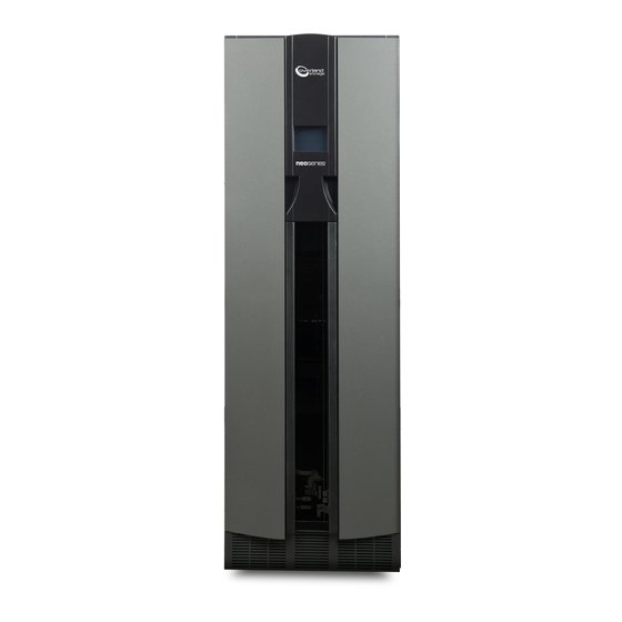
Figure 1-1: NEO 8000 Front View GUI Touch Screen The Graphical User Interface (GUI) touch screen on the front of the NEO 8000 provides an easy way to directly communicate with the library. By gently pressing the virtual buttons, you can select menus and options to change library settings. - Page 11 Figure 1-2: Mail Slot Location Media Drawers and Fixed Slots There are six media drawers (Figure 1-3) in the NEO 8000 Library. Each drawer holds up to 80 LTO cartridges. Figure 1-3: NEO 8000 Left and Right Media Drawers 1–3...
-
Page 12: Rear Components
They can also be reserved for cleaning cartridges using Menu > Library > Total Reserved Slots. The NEO 8000 comes with 1-6 drawers enabled, depending on the purchased configuration. Any disabled drawers can be activated by purchasing additional capacity and entering the... - Page 13 Library Controller Card (Req’d) Figure 1-5: NEO 8000 Rear View Power Supplies Power is routed via power cords through the base plate of the unit into connectors on the circuit breaker box at the base of the built-in power strip. The power strip contains geographically placed receptacles which make AC power available to the power supply cases without the need for routing cables.
- Page 14 Chapter 1: NEO 8000 Library Overview Foldable Handle Primary Power Supply (#1) Thumbscrew Release Power Supply Case ON/OFF Switch Redundant Power Supply (#2) Power Inputs (from bus) Figure 1-6: Power Supplies in a Power Supply Case The NEO SERIES 8000 Library has three power supply cases that distribute AC power to different portions of the library.
- Page 15 Library Design and Layout Power Circuits NEO 8000 has two power circuits to support the power redundancy option (Figure 1-7). Circuit 2 Circuit 1 (Secondary) (Primary) Receptacles Figure 1-7: NEO 8000 Circuit Breakers Showing Primary and Secondary Circuits The Primary circuit consists of the right-hand receptacle and top breaker on the circuit breaker box, the upper receptacles of the power strip, and the upper installed power supplies.
- Page 16 Chapter 1: NEO 8000 Library Overview Figure 1-8: NEO 8000 Drive Assembly (SCSI) The NEO 8000 base configurations have either zero or two drives. Additional drives can be added one at a time, as needed, until the library is fully populated with 12 drives (Figure 1-9).
- Page 17 Separate SCSI connections and ID addresses are used to control the functions of the tape drives and robotics. Virtual Interface Architecture The NEO 8000 contains two rear-access card cages and a Compact PCI backplane. This backplane contains the plug-in connectors for the library’s controller board and up to nine V.I.A. PCI cards.
- Page 18 Area Network (SAN). It includes battery backed-up memory, verbose trace log capabilities, and date/time stamp. The FCO card is designed to fit into either one of the V.I.A. bays built into the NEO 8000. Refer to the documentation that accompanies the card for more details.
- Page 19 SCSI devices and an iSCSI SAN. The GEO card is designed to fit into either one of the V.I.A. bays built into the NEO 8000. Refer to the documentation that accompanies the card for more details.
- Page 20 (i.e., partitioned or multi-module). To the external network, it functions as an endpoint device, not a network router or switch. The Router card must be installed in one of the lower option card slots of the NEO 8000. Refer to the documentation that accompanies the card for more details.
-
Page 21: Capacity Configurations
Library Design and Layout Capacity Configurations Drives 1-6 are powered by the lower power supplies that come standard on the NEO 8000. When expanding to drives 7-12, additional optional power supplies need to be installed in the upper power case (Figure 1-16). - Page 22 Chapter 1: NEO 8000 Library Overview 1–14 10400267-101 09/2009...
-
Page 23: Chapter 2 - Unpacking And Setting Up
IMPORTANT: Overland Storage recommends that all NEO 8000 Libraries be installed by an Overland Storage authorized service provider. This chapter describes how to unpack and set up a new NEO 8000 Library. This same information is also available in the NEO 8000 Library Important Unpacking Instructions located on the outside of the shipping container. - Page 24 Chapter 2: Unpacking and Setting Up Allow at least 10 ft. in Allow 3 ft. Allow 8 ft. the rear to remove the around vertical library from the pallet the library clearance Ramp Floor Figure 2-1. Unpacking Space Requirements 2. Remove the outside packaging (Figure 2-2).
-
Page 25: Detaching The Pallet
Detaching the Pallet 3. Remove the inner packaging (Figure 2-3). Top Pads RAMP Box Strap DOOR Box (Library hidden for clarity) Front Figure 2-3: RAMP and DOOR Box Locations a. Remove the two (2) pads on top of the library. b. - Page 26 Use the adjustable wrench to loosen and raise the two leveling legs (Figure 2-6). Figure 2-6: NEO 8000 Casters and Leveling Legs 3. Remove the front hardware holding the library on the pallet. NOTE: Lift the front crosspiece ends for access to the bolts, brackets, and leveling legs.
-
Page 27: Attaching The Front Doors
Attaching the Front Doors 5. Carefully move the library down the ramps and onto the floor. CAUTION: Do not pull on the media drawer handles when moving the library. Attaching the Front Doors Before moving the library to its final operating position, attach the front doors. NOTE: The square, straight end of the door is the top and the curved end is the bottom. -
Page 28: Leveling The Library
Chapter 2: Unpacking and Setting Up e. Lower the door so that the top hinge pin is above the library hinge block hole and seat it. f. Using the flat-blade offset screwdriver, unscrew the door checks in both the upper and lower library hinge blocks until the door closes freely. g. -
Page 29: Remove The Drawer Shipping Brackets
Remove the Drawer Shipping Brackets 5. Note the position of the bubble. Raise both of the front legs or both of the rear legs the same amount to achieve a level front-to-rear reading. 6. Place the level across the top front edge of the library. 7. - Page 30 Chapter 2: Unpacking and Setting Up 2–8 10400267-101 09/2009...
-
Page 31: Chapter 3 - Installation And Initialization
Installation and Initialization CHAPTER Once the NEO 8000 Library is secure and level, you need verify the basic cable connections are in place before powering on the library for the first time. Installation Considerations If the unit is installed in a closed environment it may require further evaluation by Certification Agencies. -
Page 32: Powering Up The Library
(Secondary) (Primary) Receptacles Figure 3-1: NEO 8000 Circuit Breakers (OFF Position) 3. Connect the other ends of the power cords to your AC source. 4. Set both circuit breakers to the ON position. 5. Set the power switches on the power supplies to the ON (|) position. -
Page 33: Powering Down The Library
Powering Down the Library As the POST starts, the Initialization screen appears (Figure 3-2). Figure 3-2: Initialization Screen After about 50 seconds (or if the Continue button is pressed), the Default screen appears (Figure 3-3). Figure 3-3: Library Default Screen NOTE: Though visible, this screen is not fully functional until POST completes. -
Page 34: Alternate Method
Chapter 3: Installation and Initialization Alternate Method This method can be used to bypass the controlled power-down sequence for quickly shutting down the library. 1. Press and hold the power button on the front panel for about 3 seconds. 2. Choose one of the following options from the dialog box: •... -
Page 35: Chapter 4 - Daily Operation
Daily Operation CHAPTER This chapter covers some of the configuration changes to the NEO 8000 Library that occur during everyday use. Common Configuration Modifications The library provides several configuration options to support a variety of applications and platforms. The settings for each of the available options are stored in non-volatile memory in the library. -
Page 36: Configuring A Fibre Channel Drive
Chapter 4: Daily Operation 4. Press the virtual button to the right of the tape drive you are changing. The Bus ID edit screen is displayed (Figure 4-2). Figure 4-2: Bus ID Edit Screen 5. Press one of the SCSI ID number buttons for the new ID and press Save. 6. - Page 37 Verify the firmware level of your library by selecting Menu > Library Info from the Default screen. If it needs to be upgraded, visit the Overland Storage Technical Support web site for the latest versions of the firmware. For information about downloading firmware, see “Downloading and Flashing...
-
Page 38: Creating Reserved Slots
Chapter 4: Daily Operation Figure 4-5: Edit FC Drive Configuration (Set Values) Screen 5. Make all the necessary changes by pressing the appropriate buttons and entering the new data. 6. Press Save. A dialog box appears stating the configuration is being updated, and then you are automatically returned to the FC edit screen. - Page 39 Common Configuration Modifications 2. In the Edit Options area, press Library. NOTE: If a Service password is enabled, the validate password screen is displayed. Enter the correct password and press Validate. The initial Library screen is shown (Figure 4-7). Figure 4-7: Library Initial Screen (Edit Options) 3.
-
Page 40: Media Handling
7. Press Back twice to return to the Default screen. Media Handling The tape cartridge media is the focus for most of the daily operations of a NEO 8000 Library. A library manages up to 500 cartridges including any cleaning cartridges. -
Page 41: Using Mail Slot Magazine For Small Quantity Exchanges
• Never erase information on a cartridge label—always replace the label. Using Mail Slot Magazine for Small Quantity Exchanges The NEO 8000 features a Mail Slot that allows you to import or export multiple cartridges without interrupting library operation. The Mail Slot magazine... - Page 42 Chapter 4: Daily Operation Last Slot (15) First Slot LTO Mail Slot Magazine Figure 4-12: Inserting Cartridges Into the Mail Slot Insert tape cartridges so that the bar code labels are facing outward and the tape hub is toward the left (Figure 5-12).
- Page 43 Media Handling Figure 4-13: Move Media Screen 6. Press in the Source field, select Mail Slot as the Source Element Type, and select the slot number where it is located. 7. Press in the Destination field, select a location for the tape being added as the Destination Element Type, and select the destination slot number.
-
Page 44: Using Media Drawers For Bulk Exchanges
Using Media Drawers for Bulk Exchanges There are six media drawers in the NEO 8000 Library. Each drawer holds up to 80 LTO cartridges. The first slot is located at the bottom front of the drawer and the last slot is at the... - Page 45 Master/Slave with HRA IMPORTANT: See the NEO 8000 Scalability Upgrade Installation Instructions for more details. Moving media back and forth between Master and Slave units using the HRA is the same as with a Standalone library. The move is executed at the Master GUI screen. The libraries are differentiated by the slot and drive numbering.
-
Page 46: Tape Drive Cleaning
Because a cleaning cartridge is abrasive, excessive cleaning can shorten the life of a drive. The NEO 8000 has options to either automatically or manually clean a tape drive. Most backup software also can manages the cleaning of library tape drives as a normal part of operations but it is usually based on a time limit rather than a drive need. - Page 47 Tape Drive Cleaning Running a Cleaning Cartridge from the Mail Slot 1. Install a cleaning cartridge into the Mail Slot magazine. 2. From the GUI screen, select Menu > Maintenance > Clean Drive. 3. Press the Source field and select Mail Slot as the Source Element Type. 4.
-
Page 48: Replacing A Cleaning Cartridge In A Reserved Slot
Chapter 4: Daily Operation Replacing a Cleaning Cartridge in a Reserved Slot When a tape drive detects an expired cleaning cartridge, a message appears on the front panel display. It is then necessary to replace the cleaning cartridge. 1. Use the Status screen to verify that the cleaning cartridge has been unloaded from the tape drive. -
Page 49: Chapter 5 - Graphical User Interface Usage
Graphical User Interface Usage CHAPTER The Graphical User Interface (GUI) touch screen on the front of the NEO 8000 provides an easy way to directly communicate with the library. GUI Touch Screen Figure 5-1: GUI Touch Screen Location By gently pressing the virtual buttons, you can select menus and options to view or change library settings. -
Page 50: Default Screen
From this screen you can access all options, functions, informational screens, and screen contrast adjustments of the NEO 8000. You can also initiate a controlled shutdown of the library. Tapping the logo area turns on the internal light for 30 seconds. -
Page 51: Host Lock Out
Default Screen Options The passwords for Levels 1–3 are managed using the Passwords button in the Edit Options area of the Menu. Once enabled, you are always prompted for a password whenever its associated buttons are pressed. This is especially true when trying to access or move media. When you return to the Default screen, all password access is cleared and you must reenter the password for new access. - Page 52 Chapter 5: Graphical User Interface Usage Default “Logo” Screen Contrast (Tech Support) Controls Online/ Mail Slot Drawer Move Power Status Menu Offline Access Access Media Mail 1-n Source Hi-Left (un-/relock (lock/unlock ) Destination (row 1 slots ) View System Data Mid-Left (un-/relock) Elements Lo-Left (un-/relock)
-
Page 53: Menu Button
Default Screen Options Edit Options Area Library SCSI / FC Network Passwords Set these options: Set these options: Set these options: Enter password numbers for: Library Remains Offline Drive n Bus ID (SCSI only) IP Address Determination Level 1 security After Power-Up Initialization Drive n Configuration (FC only) IP Address... -
Page 54: Online / Offline Button
Chapter 5: Graphical User Interface Usage Refer to “Menu Screen Options” on page 5-10 for complete details. Online / Offline Button Pressing this button switches the library between online and offline status. The button name changes to reflect the status that will result if it is pressed. It can be password protected using Security Level 2. -
Page 55: Power Button
Default Screen Options Pressing the appropriate feature button displays a detailed status screen. For the media drawer secondary screens, press a media row to see greater detail (Figure 5-7). Primary Status Screen Figure 5-7: Secondary and Tertiary Status Screen Examples Power Button The Power button initiates a controlled power-down sequence that provides enough time to park the robotics assembly and shuttle. -
Page 56: Mail Slot Access Button
Chapter 5: Graphical User Interface Usage Figure 5-8: Power Down Confirmation Dialog Box Mail Slot Access Button Pressing this button displays the Mail Slot Access screen (Figure 5-9). This screen lets you gain access to the Mail Slot without taking the library offline. It can be password protected using Security Level 1. -
Page 57: Move Media Button
Default Screen Options Figure 5-10: Drawer Access Screen Access is gained by pressing either a specific drawer button or the Unlock All Drawers option. To relock the drawers, either press the specific drawer button again or the Relock All Drawers option. Disabled drawers are grayed-out and inaccessible. -
Page 58: Technical Support Button
(Figure 5-12). Figure 5-12: Technical Support Screen If you are having difficulty contacting your local service provider, contact Overland Storage directly. For further assistance, you can also access Overland’s website at http:// www.overlandstorage.com. LCD Contrast Controls Pressing the up and down arrows in the upper right corner of the Default screen temporarily increases or decreases the contrast of the LCD display. -
Page 59: Library Options Button (View System Data)
Menu Screen Options IMPORTANT: The Utilities options are designed for use by Overland-Authorized Service Technicians and, with a few exceptions, are not recommended for access by end users. Figure 5-13: Menu Screen CAUTION: If you press the Diagnostics, Factory, or any Edit Option area button, the library is automatically and immediately taken offline. -
Page 60: Scsi/Fc Options Button (View System Data)
Chapter 5: Graphical User Interface Usage Figure 5-14: View Library Options Initial Screen (View System Data) Use the arrows to shift between screens. No modifications can be made on these screens. Refer to “Library Button (Edit Options)” on page 5-18 for information on changing these settings. -
Page 61: Network Options Button (View System Data)
Library Info Button (View System Data) The Library Info button in the View System Data area provides read-only access to the general information about the NEO 8000 Library. Pressing this button displays a single screen of information (Figure 5-18). -
Page 62: Cartridge Map Button (View System Data)
Chapter 5: Graphical User Interface Usage Figure 5-18: View Library Info Screen (View System Data) This screen displays the library’s firmware revision, current IP address, Ethernet address, library serial number, media drawer configuration key, and number of power-on hours. No modifications can be made on this screen. - Page 63 Resets user options back to the default values stored in non-volatile memory. The library immediately reboots upon completion. Force Reconfiguration Forces an immediate reconfiguration of the NEO 8000 to the appropriate settings of Master, Slave, or Standalone. 5–15 10400267-101 09/2009...
- Page 64 Chapter 5: Graphical User Interface Usage Table 5-3: Maintenance Submenu Button Functions (Continued) Option Description Reboot Library Forces an immediate reboot of the NEO 8000. Flash Slaves Updates the firmware of a Slave library using the Master firmware image. Load/Unload Fixed Slots Moves cartridges between the Fixed Slots and the Mail Slots.
-
Page 65: Diagnostics Button (Utilities)
Menu Screen Options Control Fans and Light Button. This option displays a menu screen (Figure 5-22) that provides buttons to turn ON and OFF the primary backplane (BP) fan, secondary BP fan, and interior light. When pressed, the button changes to show that the opposite action is now available for that feature. -
Page 66: Factory Button (Utilities)
Chapter 5: Graphical User Interface Usage Factory Button (Utilities) IMPORTANT: The Factory option is designed for use by Overland Factory Technicians and is not available for access by end users. Security Level Button (Utilities) The Security Level button in the Utilities area provides a means to validate passwords to access different security levels (Figure 5-24). - Page 67 Menu Screen Options Table 5-4: Editable Library Options Option Description Library Remains Offline Lets you enable or disable whether the library remains offline after After Power-up power-up initialization. If enabled, you must press the Online button Initialization on the Default screen to bring it online. The default is Disabled.
- Page 68 Chapter 5: Graphical User Interface Usage Table 5-4: Editable Library Options (Continued) Option Description Bar Code Label Size Lets you limit the maximum number of characters reported for the bar code label both to a host and on the Cartridge Map. Possible settings are 1 through 8.
-
Page 69: Scsi/Fc Button (Edit Options)
2-unit library system. The default is Standalone. Custom Display Lets you turn off the Overland Storage name and logo that is displayed during the POST and on the Default screen. When enabled, “Initializing” is displayed during the POST. On the Default screen, the upper left corner and logo area is left blank. - Page 70 Chapter 5: Graphical User Interface Usage Figure 5-27: FC Initial Screen (Edit Options) This table shows the different SCSI drive options available: Table 5-5: SCSI/FC Editable Options Definition Option and Default Description Drive n Bus ID Lets you set the SCSI addresses of the drives. The default addresses (SCSI drives installed) are: Drive 1 = ID 1...
- Page 71 Menu Screen Options Table 5-5: SCSI/FC Editable Options (Continued) Definition Option and Default Description Unit Attention Reporting Lets you select reporting of all or just one of the stacked-unit attention conditions. If set to Report All, the unit reports all unit attention conditions in sequence.
- Page 72 Chapter 5: Graphical User Interface Usage Table 5-5: SCSI/FC Editable Options (Continued) Definition Option and Default Description TapeAlert Mode Specifies conditions for logging and reporting the following TapeAlert data options: • Logging Disabled—Inhibits the logging feature. • No Exceptions—Information exceptions are not reported. •...
- Page 73 Menu Screen Options Table 5-5: SCSI/FC Editable Options (Continued) Definition Option and Default Description Fast Terminate Sequence This option modifies the comand sequence sent to a SCSI controller to terminate a SCSI command. The settings are Disabled or Enabled. • Select Enabled to send a single command terminate sequence. The single command terminate sequence is recognized by all SCSI host adapters and is used to accommodate Network Appliance servers using QLogic SCSI host adapters.
-
Page 74: Network Button (Edit Options)
Chapter 5: Graphical User Interface Usage Table 5-6: FC Editable Drive Options (Continued) Definition Option and Default Description Topology Specifies the topology used by the Fibre Channel ports. The four options are Use Loop, Allow Point-to-Point; Use Point-to-Point, Allow Loop; Force Loop; or Force Point-to-Point. The default is Use Loop, Allow Point-to-Point. - Page 75 Menu Screen Options This table shows the different network options available: Table 5-7: Network Editable Options Option Description IP Address Determination Lets you select the method for setting the IP address of the library's embedded WebTLC protected Internet site. The settings are Obtain IP Address From a DHCP Server or User Specified IP Address.
-
Page 76: Passwords Button (Edit Options)
5. Press Save. 6. At the Status dialog box, press OK. Additional Menu Items for Partitions When a NEO 8000 library is partitioned, additional items appear in several GUI menus to help manage those partitions. Refer to Appendix C, “Library Partitioning,”... -
Page 77: Chapter 6 - Webtlc Usage
Explorer (3.0 or higher), Firefox (1.0 or higher), or Netscape (3.0 or higher) browsers. WebTLC shows you the overall NEO 8000 status at a glance. It supports most of the same commands and controls that are available from the GUI touch screen on the front of the library (see Chapter 5, “Graphical User Interface... -
Page 78: Accessing Webtlc
Chapter 6: WebTLC Usage Accessing WebTLC Since WebTLC provides the same access and controls available from the GUI touch screen, the focus of this section is on the browser-based controls and layouts for accessing those same commands. NOTE: The library must be in the ready mode to establish communications with WebTLC. If you are unable to access the library with your browser, verify that it is not offline. - Page 79 Accessing WebTLC From the WebTLC Control Panel, you can access this information: Table 6-1: WebTLC Control Panel Buttons Icon Description Status Button Displays a visual representation of the cartridge map, library status, and drive status. † Move Media Button Lets you load or remove a cartridge from a tape drive or move cartridges within the library.
-
Page 80: Status Button
Chapter 6: WebTLC Usage Status Button The Status button displays a visual representation (Figure 6-3) providing general information about the library and each drive. Scroll down to view all the information. Clicking a drive graphic at the top takes you to the appropriate summary section at the bottom of the screen. - Page 81 Accessing WebTLC After the slot information comes the library and drive status (Figure 6-4). Figure 6-4: WebTLC Status Screen (Library Status) At the very bottom is a Full Drive Status button to view the all the information for each drive (Figure 6-5).
- Page 82 Chapter 6: WebTLC Usage Figure 6-6: Select a Drive for Full Report The selected drive is shown with complete details about its status (Figure 6-7) Figure 6-7: Full Drive Status Screen 6–6 10400267-101 09/2009...
-
Page 83: Move Media Button
Accessing WebTLC Move Media Button CAUTION: Do not move tape cartridges while the Library Applications Software is running. Fatal software faults may occur! The Move Media button lets you move a selected cartridge to a target drive or cartridge slot using drop-down lists (Figure 6-8). -
Page 84: Setup Button
Chapter 6: WebTLC Usage Figure 6-9: WebTLC Move Media Confirmation Screen 4. If you no longer want this prompt to appear, check the box next to that option. 5. If you want the move to be executed even if the library is busy, check the box next to that option. - Page 85 Accessing WebTLC Figure 6-10: WebTLC Setup Screen 6–9 10400267-101 09/2009...
- Page 86 Chapter 6: WebTLC Usage Library Configuration The Library Configuration parameters (Figure 6-11) are equivalent to the ones found on the Library (Edit Options) screens available at the GUI touch screen. Figure 6-11: WebTLC Setup > Library Configuration Screen SCSI Configuration The SCSI Configuration parameters (Figure 6-12) are equivalent to the ones found on the...
- Page 87 Accessing WebTLC Figure 6-12: WebTLC Setup > SCSI Configuration Screen 6–11 10400267-101 09/2009...
- Page 88 Chapter 6: WebTLC Usage Drive Configuration When Drive Configuration is selected, a selection screen is displayed (Figure 6-13). Figure 6-13: Drive Selection Screen for Setup Choose a drive from the list and click Select the Drive to be Configured. The Drive n Configuration screen appears (Figure 6-14).
- Page 89 Accessing WebTLC Capacity Configuration The Capacity Configuration parameters (Figure 6-15) are equivalent to ones found on the GUI touch screen. Figure 6-15: WebTLC Setup > Capacity Configuration Screen Notification Registration The Notification Registration parameters (Figure 6-16) are equivalent to ones found in the NeoCenter8000 utility.
- Page 90 Chapter 6: WebTLC Usage Figure 6-16: WebTLC Setup > Notification Registration Screen 6–14 10400267-101 09/2009...
-
Page 91: Functions Button
Accessing WebTLC Functions Button The Functions button provides controls for these maintenance functions: • Library Flash Operation—updates the library’s firmware from a file. • Drive Flash Operation—updates a drive’s firmware from a file. • Perform a Drive Cleaning Operation—the same as Clean Drive under the Maintenance menu group. - Page 92 Chapter 6: WebTLC Usage Figure 6-17: WebTLC Functions Option 6–16 10400267-101 09/2009...
- Page 93 NOTE: M##H.FRM is used for a different program. Do not download this file. Follow these steps to download either firmware for use as a Local File: 1. Connect to the Overland Storage FTP site. 2. For tape drive firmware, locate the proper tape drive directory.
-
Page 94: History Button
Chapter 6: WebTLC Usage d. Click Start the Flash, select the firmware file name, and click OK. When the flash operation is finished, WebTLC displays a completion message. History Button The History button provides access to the library trace logs (Figure 6-18). -
Page 95: Chapter 7 - Neo8000Center Usage
Neo8000Center Usage CHAPTER The Neo8000Center software allows you to access and control the NEO 8000 Library from a Windows-based PC. It supports most of the same commands and controls that are available from the GUI touch screen on the front of the library. It is also the only way to partition a library. -
Page 96: Configuring The Library Using Neo8000Center
Neo8000Center can be used to configure the library just like the front panel GUI. This is managed by establishing communication between the host and the library, opening the configuration dialog box, making the changes, and then saving the changes. For more details about NEO 8000 configuration options, refer to Chapter 5, “Graphical User Interface Usage.”... - Page 97 Figure 7-2: Serial Port Setting Dialog Box 6. Verify the COM port settings, and click OK. NOTE: If the connection is not successful, check all cable connections and retry the connection. If communication fails again, contact Overland Storage Technical Support. 7–3 10400267-101 09/2009...
-
Page 98: Launching The Configuration Dialog Box
Chapter 7: Neo8000Center Usage Launching the Configuration Dialog Box After establishing communications, from the Neo8000Center main menu, choose Configure > Set Values. The Configure Library dialog box appears (Figure 7-3). Figure 7-3: Configure Library Dialog Box—IP Addresses Tab IP Addresses Tab Use the IP Address tab (Figure 7-3) to set the IP addresses used to access WebTLC on the... - Page 99 Configuring the Library Using Neo8000Center SNMP Tab These settings enable the WebTLC to send system events asynchronously to the network. NOTE: Configuration addresses are network specific. Contact your network system administrator for the appropriate values. 1. Click the SNMP tab to bring it to the front (Figure 7-4).
- Page 100 Chapter 7: Neo8000Center Usage E-mail Addresses Tab These addresses are sent an e-mail upon notification of specific system events. 1. Click the E-mail Addresses tab to bring it to the front (Figure 7-5). Figure 7-5: Configure Library Dialog Box—E-mail Addresses Tab 2.
- Page 101 Configuring the Library Using Neo8000Center SCSI Identification 1. Click the SCSI Identification tab to bring it to the front (Figure 7-6). Figure 7-6: Configure Library Dialog Box—SCSI Identification Tab 2. Establish the SCSI ID and settings for the library using these options: •...
- Page 102 Chapter 7: Neo8000Center Usage SCSI Parameters 1. Click the SCSI Parameters tab to bring it to the front (Figure 7-7). Figure 7-7: Configure Library Dialog Box—SCSI Parameters Tab 2. Set the SCSI parameters using these options: • Use the eight drop-down lists to choose the basic parameters. •...
- Page 103 Configuring the Library Using Neo8000Center Library Parameters 1. Click the Library Parameters tab to bring it to the front (Figure 7-8). Figure 7-8: Configure Library Dialog Box—Library Parameters Tab 2. Set the general parameters for the library using these options: •...
- Page 104 Chapter 7: Neo8000Center Usage Drives Tab 1. Click the Drives tab to bring it to the front (Figure 7-9). Figure 7-9: Configure Library Dialog Box—Drives Tab (SCSI) 2. If applicable, check the box to activate the Auto-Install feature. 3. Set or change the SCSI IDs for the SCSI tape drives or configure FC drives, click the appropriate Configure Drive n button.
- Page 105 Configuring the Library Using Neo8000Center Figure 7-10: Configure Drive n Screen • SCSI Drive – Select the SCSI ID for the drive. • FC Drive – Enter the appropriate information in the FC fields. 4. Click OK to save the settings and return to the Drive tab. 5.
- Page 106 These settings enable the user to download firmware to the WebTLC or to your Library via a remote FTP site. Contact Technical Support for the current User ID and Password to reach Overland Storage’s FTP site. 1. Click the Remote FTP Server tab to bring it to the front (Figure 7-11).
- Page 107 Configuring the Library Using Neo8000Center Access Tab Since WebTLC permits total control over a library, those capabilities must be limited to the appropriate users. This is managed by passwords set on the Neo8000Center configuration screen. There are two different levels of system access available: •...
-
Page 108: Exiting The Configuration Screen
Chapter 7: Neo8000Center Usage Factory and Fiducial Calibration Tabs IMPORTANT: The options on the Factory and Fiducial Calibration tabs are designed for use by Overland Authorized Service Technicians and is not recommended for access by end users. Exiting the Configuration Screen Once you have completed making your configuration settings, you are prompted to confirm these changes as you exit the dialog box. - Page 109 Uploading Data Files Figure 7-15: Upload Data From Library Screen 3. Set or change upload settings using these options: • Select the Type of trace by clicking the System Trace, Non-Volatile Trace, Special Trace, or Servo Trace button. • If necessary, select the library being traced from the Select Module area. If tracing a partition, enter the Partition Number.
-
Page 110: Downloading Data Files
5. Click OK to return to the main Neo8000Center screen. NOTE: If flash programming does not complete, check all cable connections and repeat the download steps. If it fails a second time, contact Overland Storage Technical Support. 7–16 10400267-101 09/2009... -
Page 111: Viewing Library Information
Viewing Library Information Viewing Library Information The Info option displays a screen showing the basic information about the library. Figure 7-18: Library Info Screen Generating a Post-Process Report Sometimes it is beneficial to generate a trace log to view the status of the library and some or all of its components. - Page 112 Chapter 7: Neo8000Center Usage Figure 7-20: Post-Process Select Files Screen 5. Use the Browse buttons to select the binary, database, and post-processed files used for the trace log, then click OK. 6. Choose Post-Process > Process and Display from the Neo8000Center menu. Notepad opens and the trace log is shown (Figure 7-21).
-
Page 113: Rebooting The Library With Neo8000Center
Rebooting The Library With Neo8000Center Figure 7-22: Post-Process Display Screen Rebooting The Library With Neo8000Center If it becomes necessary to reboot the library, this can be accomplished using the Neo8000Center program. 1. Establish communications with the library, if not already established. 2. - Page 114 Chapter 7: Neo8000Center Usage 3. Click Yes. A library rebooting message box appears (Figure 7-24). Figure 7-24: Library Rebooting Message 4. Click OK. The library disconnects as it reboots. You must manually reestablish communications to continue using Neo8000Center with the library. 7–20 10400267-101 09/2009...
-
Page 115: Chapter 8 - Cabling Options And Examples
Cabling Options and Examples CHAPTER The following figures show some of the common NEO 8000 cabling configurations for both Fibre Channel (FC) and SCSI drives. CAUTION: This equipment has been tested for electromagnetic emissions and immunity using good quality shielded cables. If you use unshielded or poor quality cables, or otherwise vary from good practice, you might not comply with national and international rules. -
Page 116: Scsi Drive Cabling Examples
Single Host SCSI Network with Two SCSI Drives The most basic NEO 8000 system consists of two drives connected to the Library Controller card (LCC) on a SCSI network (Figure 8-1). -
Page 117: Fibre Channel Network With Two Scsi Drives
SCSI Drive Cabling Examples Fibre Channel Network with Two SCSI Drives Some other SCSI cable configurations for an NEO 8000 library use two SCSI drives installed with a dual host system on a FC network (Figure 8-2). In this example, the SCSI drives are connected to a FC SAN via an FCO card by using different SCSI ports, one on the FCO card and one on the Library Controller card, for the different drive buses. -
Page 118: Four Scsi Drives On A Two Host Scsi Network
Chapter 8: Cabling Options and Examples Four SCSI Drives on a Two Host SCSI Network Another typical SCSI cable configuration for an NEO 8000 library is four SCSI drives installed using a dual host on a SCSI network (Figure 8-3). -
Page 119: Fibre Channel Cabling Examples
Figure 8-4: Typical Native Fibre Channel Configuration Multi-FCO Card System Configuration The NEO 8000 Library can be expanded to handle up to 12 drives. As the number of drives increases, the placement of the FCO cards in the primary and secondary card cages becomes... - Page 120 Chapter 8: Cabling Options and Examples Terminators SCSI Cables Fibre Connections Terminators SCSI Cables Fibre Connections Figure 8-5: Maximum FCO Card Configuration 8–6 10400267-101 09/2009...
-
Page 121: Chapter 9 - Component And Capacity Additions
Component and Capacity Additions CHAPTER The NEO 8000 is a scalable appliance that allows you to easily add more drives, power supplies, special feature interface cards, and capacity. WARNING: The GUI touch screen does not completely shut off library system power. To reduce the risk of electric shock or damage to equipment, disconnect power by unplugging the power cords before making any component additions. -
Page 122: Additional Drive Assemblies
6. Turn on both power supplies. Additional Drive Assemblies IMPORTANT: Overland Storage requires that all NEO 8000 drives be installed or replaced by an Overland Storage authorized service provider. Improper installation may result in damage which voids existing warranties. -
Page 123: Adding Capacity
Adding Capacity Adding Capacity The NEO 8000 Expansion-on-Demand feature allows you to increase your library capacity up to as many as 500 cartridge slots depending upon your data center needs. Simply entering a 32-character key code from the user interface, serial port, or remotely using WebTLC adds to the storage capacity of your library. -
Page 124: Scalability Option - Horizontal Robotics Assembly
The NEO 8000 architecture can be expanded by adding a second library unit. A Horizontal Robotics Assembly (HRA) is installed inside the two connected NEO 8000 libraries to enable... -
Page 125: Appendix A - Neo 8000 Specifications
NEO 8000 Specifications APPENDIX The NEO 8000 tape library comes in different configurations based on capacity and drive type. Table A-1: Physical Characteristics All Models Specifics Dimensions (H x W x D) 76 x 24 x 41.5 in. (193 x 61 x 105 cm) Base Configuration Shipping Weight 705 lb. - Page 126 Appendix A: NEO 8000 Specifications Table A-4: Reliability Feature Specifics MTBF More than 250,000 hours MSBF More than 2,000,000 cartridge swaps Design Life 7 years MTTR Less than 15 minutes Maximum time to repair 1 hour Table A-5: Safety Agency...
- Page 127 Table A-7: Temperature, Humidity & Altitude Operating Dry Bulb Temperature 10°C to 40°C Temperature Gradient 1°C / min. (across the range) Temperature Shock 15°C (over 2 min.) Wet Bulb Temperature 26°C Relative Humidity 15% to 85% (noncondensing) Humidity Gradient 10% / hr. Altitude (Sea Level) -1000 ft.
- Page 128 Appendix A: NEO 8000 Specifications Table A-7: Temperature, Humidity & Altitude (Continued) Relative Humidity 5% to 95% (noncondensing) Humidity Gradient 10% / hr. Altitude (Sea Level) -1000 ft. to +50,000 ft. Table A-8: Shock Operating (Within Spec—No Damage) Peak Acceleration 1.5 G's...
- Page 129 Table A-9: Vibration (Continued) Frequency Range 5–1000–5Hz Peak Acceleration 1.0 G Wave shape Sinusoidal, 1 octave/min. Application X,Y,Z axes 2 sweeps per axis Transit/Storage (Packed—No Damage) Random Vibration Test ASTM D4728-95 Considerations Air and Truck only Table A-10: Power Consumption Status Power Consumed Idle State...
- Page 130 Appendix A: NEO 8000 Specifications Table A-13: Power Supply Rating Range NOTE: The low voltage nominal will be 110 VAC and the high voltage nominal will be 220 VAC. Input Frequency 47-63 Hz Two IEC320-C20 type rear-panel receptacles AC Power Input A–6...
-
Page 131: Fcc Notice
FCC Notice FCC Notice This equipment has been tested and found to comply with the limits for a Class A digital device, pursuant to Part 15 of the FCC rules. These limits are designed to provide reasonable protection against harmful interference when the equipment is operated in a commercial environment. -
Page 132: Declaration Of Conformity
Appendix A: NEO 8000 Specifications Declaration of Conformity A–8 10400267-101 09/2009... -
Page 133: Appendix B - Repacking For Shipment To A New Location
Location APPENDIX Should it become necessary to transport your NEO 8000 Library to another location, use the following procedure to package and secure it for shipment. If you did not save the packaging materials or they were damaged, new materials can be ordered from Overland Technical Support. -
Page 134: Removing The Front Doors
Chapter B: Repacking for Shipment to a New Location • Allow at least 10 feet of clear space on the back side of the pallet (labeled “RAMP SIDE”). • Allow about 3 feet of clearance around the other three sides of the pallet. •... -
Page 135: Attaching The Drawer Shipping Brackets
Attaching the Drawer Shipping Brackets a. Lift the bottom hinge pin until it clicks into the door hinge. b. Lift the top hinge pin until it clicks into the door hinge. c. Carefully lift the door up and off the library hinge blocks and set aside. d. -
Page 136: Attaching The Pallet
(Figure B-5). Figure B-5: NEO 8000 Casters and Leveling Legs WARNING: Most of the weight of a library is in the rear of the unit. If the leveling legs are not raised high enough, they can catch at the bottom of the ramps, tipping over the library unit. - Page 137 Attaching the Pallet CAUTION: Do not pull on the media drawer handles when moving the library. 6. Attach the front hardware to hold the library on the pallet. a. Lower the leveling legs until they almost touch the pallet. b. Insert the front crosspiece into the proper slots on the pallet. c.
-
Page 138: Attaching The Outer Carton
Chapter B: Repacking for Shipment to a New Location Attaching the Outer Carton Once the NEO 8000 is secured to the pallet, the outer packaging can be added. 1. Add the inner packaging (Figure B-7). Top Pads RAMP Box Strap... - Page 139 5. Position the four (4) long reinforcing corners at each corner of the box (Figure B-8). 6. Horizontally wrap the container with strapping material about 6” (15 cm) below the tops of the reinforcing corners. The NEO 8000 Library is now ready to ship. B–7 10400267-101 09/2009...
- Page 140 Chapter B: Repacking for Shipment to a New Location B–8 10400267-101 09/2009...
-
Page 141: Appendix C - Library Partitioning
For example, in a fully loaded NEO 8000 library, the maximum number of drawers is six, which allows the configuration of up to six SCSI devices using five LPO cards (with the sixth partition being managed by the Library Controller card). -
Page 142: Installing A Router Card
Library Controller and an installed Partition Controller card. It provides a way for WebTLC to interface with the NEO 8000 when in a partitioned configuration. To the external network, it functions more as an endpoint device and not as a network router or switch. -
Page 143: Installing A Partition Controller Card
Installing a Partition Controller Card CAUTION: The internal Router card is designed to function only in the Primary card cage V.I.A. option bays (excluding the far right slot reserved for the Library Controller card). It does not function in the Secondary (upper) card cage. 4. -
Page 144: Additional Menu Items For Partitions
7. Power up the library. Figure C-4: Inserting the Partition Controller Card into the Library Additional Menu Items for Partitions When a NEO 8000 library is partitioned, additional items appear in several GUI menus to help manage the partitions. Table C-1 addresses those new options: C–4... -
Page 145: Cabling Configuration Examples
The following example (Figure C-5) shows how to connect four LTO-2 drives into two partitions in a NEO 8000. The basic steps also work in other NEO SERIES libraries. CAUTION: The Library Controller and LPO Partition Controller cards must be terminated before enabling and configuring partitioning. - Page 146 • Connect Drive 3 to Drive 4. • Install a terminator on Drive 3. 3. Using the SCSI ports, connect the NEO 8000 to the Host systems. • Connect the Library Controller (PØ) to Host 1. • Connect the Partition Controller (P1) to Host 2.
- Page 147 NOTE: Be sure to connect directly to the Host computer with the Neo8000Center software installed on it and NOT the general network. 6. If desired, connect the Router WAN port to the WAN. 7. Power up the NEO 8000. 8. Using Neo8000Center, configure the partitions. See the “Neo8000Center Usage”...
- Page 148 Chapter C: Library Partitioning C–8 10400267-101 09/2009...
- Page 149 Glossary NOTE: This is a general Overland Storage glossary and acronym list. Not all items may be found in this document or be used by this product. 1000BASE-T 1000BASE-T (also known as IEEE 802.3ab) is a standard for gigabit Ethernet over copper wiring.
- Page 150 Glossary Bus or Channel A common physical path composed of wires or other media, across which signals are sent from one part of a computer to another. A channel is a means of transferring data between modules and adapters, or between an adapter and SCSI devices. A channel topology network consists of a single cable trunk that connects one workstation to the next in a daisy-chain configuration.
- Page 151 Glossary Failover/Failback A combination of Failover and Failback. When a preferred path becomes unavailable, another path is used to route I/O until the preferred path is restored. In this case I/O will “fail back” to the preferred path once it is available again. FC-AL Short for Fibre Channel Arbitrated Loop.
- Page 152 Glossary I/E Element A configurable import/export slot or magazine to provide a means of exchanging tape media while the unit is still operating. Internet A global network of networks used to exchange information using the TCP/IP protocol. It allows for electronic mail and the accessing ad retrieval of information from remote sources. Initiator Device A system component that originates an I/O command over an I/O bus or network.
- Page 153 Glossary Short for Logical Unit Number. A SCSI or Fibre Channel device identifier. LUN is a subdivision of a SCSI target. Short for Low Voltage Differential. LVD is a method of powering SCSI cables that will be formalized in the SCSI-3 specifications. LVD uses less power than the current differential drive (HVD), is less expensive, and allows for higher speeds such as those of Ultra-2 SCSI.
- Page 154 Glossary NL_port A Node Loop port is capable of arbitrated loop functions and protocols. An NL_Port connects via an arbitrated loop to other NL_Port and at most a single FL_Port. NL_Ports handle creation, detection, and flow of message units to and from the connected systems. NL_Ports are end ports in virtual point-to-point links through a fabric, for example NL_Port to F_Port to F_Port to N_Port using a single Fibre Channel fabric switch.
- Page 155 Glossary Round Robin The Round Robin path selection policy causes all healthy paths to be used for I/O. Paths are used in a round-robin order. Router A router is a device that enables connectivity between Ethernet network segments. Short for Storage Area Network. A shared storage architecture connecting computers and storage devices for online data access.
- Page 156 Glossary SCSI port A SCSI port is an opening at the back of a router that provides connection between the SCSI adapter and SCSI bus. Storage Area Network See SAN. Tape Cartridge A magnetically coated strip of plastic in a plastic housing on which data can be encoded. Storing data on tapes is considerably cheaper than storing data on disks.
- Page 157 Glossary USB (Universal Serial Bus) Port A hardware interface for low-speed peripherals such as the keyboard, mouse, joystick, scanner, printer, and telephony devices. VLAN Short for Virtual LAN. It consists of a network of computers that behave as if they are connected to the same wire - even though they may actually be physically connected to different segments of a LAN.
- Page 158 Glossary GL–10 10400267-101 09/2009...
- Page 159 Index Status button ..........5-6 technical support button (logo) ....5-10 accessing WebTLC .......... 6-2 Diagnostics button ........5-17 accessories included........1-1 door shipping brackets, removal .... 2-7, B-3 adding components ......... 9-1 downloading firmware ......... 7-16 adding drives........... 3-1 Drawer Access screen ........
- Page 160 Index Horizontal Robotics Assembly (HRA) ... 9-4 numbering ..........4-10 numbering with HRA......4-11 host lock out ........... 5-3 Menu screen ........... 5-5 host system requirements ......8-1 Cartridge Map button ......5-14 HRA robotics overview........9-4 Diagnostics button ........5-17 HVD SCSI systems ........
- Page 161 Index Power button ........... 5-7 cleaning ........... 4-12 installing additional ......... 9-2 power down procedures ........3-3 numbering sequence ......... 1-8 power redundancy........... 1-6 technical support........ PR-iv, 5-10 power supplies tools needed ............ 2-1 installing additional ......1-13, 9-1 overview ............. 1-5 turning on the internal light ......
- Page 162 Index IX–4 10400267-101 09/2009...
Need help?
Do you have a question about the NEO 8000 and is the answer not in the manual?
Questions and answers