Table of Contents
Advertisement
Operating Manual
Translation of the original operating manual
MK (E3.1)
Alternating climate chambers with program control
Model
Model version
MK 115
MK115-400V
MK115-400V-C
MK 240
MK240-400V
MK240-400V-C
MK 720
MK720-400V
MK720-400V-C
MKT (E3.1)
Alternating climate chambers with deep temperature
and program control
Model
Model version
MKT 115
MKT115-400V
MKT115-400V-C
MKT 240
MKT240-400V
MKT240-400V-C
MKT 720
MKT720-400V
MKT720-400V-C
BINDER GmbH
Address: Post office box 102, 78502 Tuttlingen, Germany Phone: +49 7462 2005 0
Fax: +49 7462 2005 100 Internet: http://www.binder-world.com
E-mail: info@binder-world.com Service Hotline: +49 7462 2005 555
Service Fax: +49 7462 2005 93 555 Service E-Mail: service@binder-world.com
Service Hotline USA: +1 866 885 9794 or +1 631 224 4340 x3
Service Hotline Asia Pacific: +852 390 705 04 or +852 390 705 03
Service Hotline Russia and CIS: +7 495 988 15 16
Issue 07/2017
Art. No.
9020-0175, 9120-0175
9020-0290 (with voltage and frequency changer)
9020-0181, 9120-0181
9020-0294 (with voltage and frequency changer)
9020-0197, 9120-0197
9020-0298 (with voltage and frequency changer)
Art. No.
9020-0151, 9120-0151
9020-0292 (with voltage and frequency changer)
9020-0196, 9120-0196
9020-0296 (with voltage and frequency changer)
9020-0082, 9120-0082
9020-0300 (with voltage and frequency changer)
Art. Nr. 7001-0222
Advertisement
Table of Contents

Related Manuals for Binder MK 115


Summary of Contents for Binder MK 115
- Page 1 Fax: +49 7462 2005 100 Internet: http://www.binder-world.com E-mail: info@binder-world.com Service Hotline: +49 7462 2005 555 Service Fax: +49 7462 2005 93 555 Service E-Mail: service@binder-world.com Service Hotline USA: +1 866 885 9794 or +1 631 224 4340 x3 ...
-
Page 2: Table Of Contents
Contents SAFETY ........................5 Legal considerations ........................... 5 Structure of the safety instructions ...................... 5 1.2.1 Signal word panel ........................5 1.2.2 Safety alert symbol ........................6 1.2.3 Pictograms ..........................6 1.2.4 Word message panel structure ....................7 Localization / position of safety labels on the chamber ..............7 Type plate ............................ - Page 3 15.5 Keyboard locking (option) ......................... 57 15.6 Compressed air dryer (option) ......................58 15.7 Water cooling (available via BINDER INDIVIDUAL customized solutions) ........59 15.8 Additional measuring channel for digital object temperature indicator with flexible temperature sensor Pt 100 (option) ........................59 16.
- Page 4 17.4 Disposal of the chamber in the member states of the EU except for the Federal Republic of Germany ............................66 17.5 Disposal of the chamber in non-member states of the EU ............... 67 18. TROUBLESHOOTING ..................68 19. TECHNICAL DESCRIPTION ................70 19.1 Factory calibration and adjustment ....................
-
Page 5: Safety
Understanding and observing the instructions in this operating manual are prerequisites for hazard-free use and safety during operation and maintenance. In no event shall BINDER be held liable for any dam- ages, direct or incidental arising out of or related to the use of this manual. -
Page 6: Safety Alert Symbol
WARNING Indicates a potentially hazardous situation which, if not avoided, could result in death or serious (irreversible) injury CAUTION Indicates a potentially hazardous situation which, if not avoided, may result in moderate or minor (reversible) injury CAUTION Indicates a potentially hazardous situation which, if not avoided, may result in damage to the product and/or its functions or of a property in its proximity. -
Page 7: Word Message Panel Structure
Service label Figure 1: Position of labels on the chamber Keep safety labels complete and legible. Replace safety labels that are no longer legible. Contact BINDER service for these replacements. MK / MKT (E3.1) 07/2017 page 7/104... -
Page 8: Type Plate
78532 Tuttlingen / Germany www.binder-world.com Figure 2: Type plate (example of MKT 240 regular chamber) Indications of the type plate (example) Information BINDER Manufacturer: BINDER GmbH MKT 240 Model MKT 240 Alternating climate chamber Device name Serial No. 00000000000000 Serial no. of the chamber... -
Page 9: General Safety Instructions On Installing And Operating The Chamber
213-850 on safe working in laboratories (formerly BGI/GUV-I 850-0, BGR/GUV-R 120 or ZH 1/119, issued by the employers’ liability insurance association) (for Germany). BINDER GmbH is only responsible for the safety features of the chamber provided skilled electricians or qualified personnel authorized by BINDER perform all maintenance and repair, and if components relat- ing to chamber safety are replaced in the event of failure with original spare parts. - Page 10 Familiarize yourself with the physical and chemical properties of the charging material, as well as the contained moisture constituent and its behavior with the addition of heat energy. Familiarize yourself with any potential health risks caused by the charging material, the contained mois- ture constituent or by reaction products that may arise during the temperature process.
-
Page 11: Intended Use
Such ingredients include in particular acids and halides. Any corrosive damage caused by such ingredients is excluded from liability by BINDER GmbH. In case of foreseeable use of the chamber there is no risk for the user through the integration of the chamber into systems or by special environmental or operating conditions in the sense of EN 61010- 1:2010. -
Page 12: Operating Instructions
Operating instructions Depending on the application and location of the chamber, the operator of the alternating climate cham- ber must provide the relevant information for safe operation of the chamber in a set of operating instruc- tions. Keep these operating instructions with the chamber at all times in a place where they are clearly visible. -
Page 13: Chamber Description
APT-COM™ 3 DataControlSystem (option, chap. 15.1). The chamber comes regularly equipped with an Ethernet serial interface for computer communication. In addition, the BINDER commu- nication software APT-COM (option) permits networking up to 30 chambers and connecting them to a PC for controlling and programming, as well as recording and representing temperature data. -
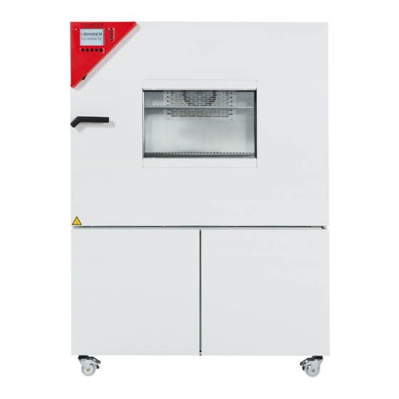
Page 14: Chamber Overview
Chamber overview Figure 3: Alternating climate chamber (example: MKT 240) Instrument panel Door handle Inspection window Chamber door Refrigerating machine, maintenance access flaps MK / MKT (E3.1) 07/2017 page 14/104... -
Page 15: Lateral Control Panel
Lateral control panel (9a) (9b) (10b) (10a) (12) (11) (13) (14) (15) Figure 4: Lateral control panel at the right side of the refrigerating machine, with options Main power switch Not used RESET button for option over-/under temperature safety device class 2 (option) Key switch for keyboard locking (option) Not used Switch for compressed air dryer (option) -
Page 16: Instrument Panel
Instrument panel Figure 5: Triangle instrument panel Microprocessor program controller MB1 Switch for interior chamber light Rear power switch (16) Figure 6: Rear view of the chamber Main power switch (16) Rear power switch MK / MKT (E3.1) 07/2017 page 16/104... -
Page 17: Completeness Of Delivery, Transportation, Storage, And Installation
Note on second-hand chambers (Ex-Demo-Units): Second-hand chambers are chambers that were used for a short time for tests or exhibitions. They are thoroughly tested before resale. BINDER ensures that the chamber is technically sound and will work flawlessly. Second-hand chambers are marked with a sticker on the chamber door. Please remove the sticker befo- re commissioning the chamber. -
Page 18: Guidelines For Safe Lifting And Transportation
Without the pallet the chamber is in imminent danger of overturning. • Permissible ambient temperature range during transport: -10 °C / 14 °F to +60 °C / 140 °F. You can order transport packing and pallets for moving or shipping purposes from BINDER service. Storage Intermediate storage of the chamber is possible in a closed and dry room. - Page 19 CAUTION Danger of overheating. Damage to the chamber. ∅ Do NOT set up chambers in non-ventilated recesses. Ensure sufficient ventilation for dispersal of the heat. • Permissible ambient temperature range during operation: +18 °C / 64.4 °F to +32 °C / 89.6 °F. At ele- vated ambient temperature values, fluctuations in temperature can occur.
-
Page 20: Installation And Connections
Installation and connections (18) (19) (16) (17) Figure 8: Rear view of the chamber with optional water cooling (16) Power cable (17) Rear power switch (18) Connection “OUT” for cooling water outlet with screw thread ¾’’ for hose ½“, with union nut (option water cooling) (19) Connection “IN”... -
Page 21: Connection Of Cooling Water Outlet For Water Cooling (Option)
• pH value 4-7 • connection pressure: 4 to 10 bar BINDER GmbH is NOT responsible for the water quality at the user’s site. Any problems and malfunctions that might arise following use of water of deviating quality is excluded from liability by BINDER GmbH. -
Page 22: Installation Of The Voltage And Frequency Changer (Chambers With Voltage And Frequency Changer)22
Installation of the voltage and frequency changer (chambers with voltage and frequency changer) The voltage and frequency changer is supplied packed separately together with the alternating climate chamber. CAUTION Sliding or tilting of the voltage and frequency changer. Damage to the voltage and frequency changer. Risk of injury by lifting heavy loads. -
Page 23: Electrical Connection
2700 mm / 8.9 ft in length and are equipped with 3 internal overload releases against excess- current. Nominal voltage ± 10% Model Power plug Current type Chamber fuse at the indicated power frequency MK 115 MK 240 CEE plug 16 Amp MK 720 400 V at 50 Hz 3 N~ 5-poles, 16 Amp... -
Page 24: Connecting The Voltage And Frequency Changer (For Chambers Equipped With A Voltage And Frequency Changer)
4.4.2 Connecting the voltage and frequency changer (for chambers equipped with a voltage and frequency changer) The voltage and frequency changer is supplied with a fixed power connection cable without a plug. It is protected against excess-current with 3 internal overload releases. The connection is made by the cus- tomer.. -
Page 25: Start Up
Figure 11: Power switch (H) of the voltage and frequency changer in position “ON” In position “OFF” the switch can be locked, e.g. with a padlock. Start up After connecting the electrical supply (chap. 4), you can start up the chamber. •... -
Page 26: Operating Modes
500. Programming can be done directly through the keypad of the controller or graphically through the soft- ware APT-COM™ 3 DataControlSystem (option, chap. 15.1) specially developed by BINDER. Performance after power failures After the power returns, the chamber continues to function in the original operating mode it was in previ- ously before an actual power failure had occurred. -
Page 27: Turning On The Chamber
Turning on the chamber Turn on the rear power switch (16) at least one hour before operating the chamber. Set the main power switch (3) to position I. The pilot lamp shows the chamber is ready for operation. Observe a delay time of approx. 30s between turning Off and again On the main power switch (3). -
Page 28: Controller Mb1 Settings
Controller MB1 settings Selection of the menu language The display program controller MB1 controls the temperature inside the chamber. The controller com- municates by a menu guide using real words in German, English and French. The selection of the desired menu language is located in the sub-menu “User-Level” of the “User- Settings”... -
Page 29: Overview Of Program Controller Mb1 Displays
VIEW -> www.binder-world.com plays. CONFIG VIEW-> VIEW-> The NORMAL DISPLAY enables comparison of the current temperature (W) to the set-point value (X). BINDER Service contact display. NORMAL DISPLAY Idle Mode 08:43:55 15.12.13 08:43:55 15.12.13 26.8 26.8 X - TEMP °C °C... -
Page 30: Menu Settings In The "User-Settings" Menu
Menu settings in the “User-settings” menu User-settings Instrument data Contrast Displ. Power down Contin. operation User Level Safety control. Set. + 110.0 °C Safety control. Act + 100.8 °C Instrument data • Instrument Name Enter an individual name of the alternating climate chamber. •... -
Page 31: Menu Settings In The "User Level" Menu
Menu settings in the “User Level” menu User Level Date and time Summer time Language English Temperature unit °C Buzzer Active Safety controller User-code No. Date and time Enter the actual date and time to provide the proper measurement records. Data is displayed in the chart recorder function (chap. -
Page 32: Graphic Representation Of The Historical Measurement (Chart Recorder Function)
Graphic representation of the historical measurement (chart recorder function) The representation of data imitates a chart recorder and allows recalling any set of measured data of any point of time taken from the recorded period. Normal display of the chart recorder function: Top left: The actual date and time are displayed. - Page 33 You can also directly enter any cursor position as a numerical input. History representation: Toggling to any defined moment: 11:34:27 15.12.13 Press button . The window “Cursor position” Cursor opens to enter date and time. position Date 15.05.13 Time 11:32:48 Select date or time with the arrow buttons and confirm with ENTER.
-
Page 34: Setting The Storage Rate
Setting the storage rate 11:44:17 20.12.13 User-Settings Configuration 2 Configuration 1 CONFIG Parameters Choose variation 11:44:17 20.12.13 User-Settings Configuration 2 Configuration 1 Parameters Choose variation User-Code ? Grenzwert +00001 Offset Configuration 1 Diagram view Feed view Time/div Event tracks Datalogging Interface Analog view Datalogging... -
Page 35: Manual Mode
Manual Mode In Manual Mode (HAND) you can enter a temperature set-point and the switching-state of up to 8 opera- tion lines. Operation line 1 is used to control the bedew protection (chap. 10). Operation lines 2 to 5 serve to switch any device connected to the zero-voltage relay outputs (DIN sockets (8) and (9), MKT, option for MK, chap. -
Page 36: Performance After Power Failure In Manual Mode
MK, chap. 11). Operation line 8 releases the compressed air dryer (option, chap. 15.6). The other operation lines are non-functional. Programming is possible directly by the keypad of the controller or graphically by the software APT- COM™ 3 DataControlSystem (option, chap. 15.1) specially developed by BINDER. MK / MKT (E3.1) 07/2017 page 36/104... -
Page 37: Menu-Based Program Entry
Menu-based program entry Display showing the initial normal display in Idle Mode 08:43:55 15.12.13 26.8 °C TEMP CONFIG HAND VIEW-> Press the “PGM” button. The window program selection appears 08:43:55 15.12.13 Prog select Fr. Abs. 372 Prog 1 PROG 01 ... - Page 38 Press the “PGM” button. An inquiry display appears allowing you to enter or delete individual program sections: ZP-Abschnitt Abs. Nr. 5 insert delete In this view, new program lines can be entered or deleted: New lines are added below in the table insert New lines are added above a previously selected line delete...
-
Page 39: Selecting Between Set-Point Ramp And Set-Point Step
Selecting between set-point ramp and set-point step Temperature set-points always refer to the start of a program section, i.e., at the beginning of each pro- gram section the entered temperature set-point is targeted. During program section operation, the tem- perature gradually passes to the set-point entered for the next section. By appropriate planning of the program section timing, you can enter all kinds of temperature transitions. - Page 40 Program entry as set-point ramp (example) W/°C Maximum tolerance Minimum tolerance t/min. Operation line 1 = bedew protection t/min. Operation line 2 t/min. Operation line 3 t/min. Operation line 4 t/min. Operation line 5 t/min. Operation line 8 t/min. MK / MKT (E3.1) 07/2017 page 40/104...
- Page 41 Program table corresponding to the diagram above: Operation lines Program Temp. Section Target No. of Minimum Maximum section set-point time section cycles tolerance tolerance Time Tmin Tmax ****. 00:30:00 0 -1999 +9999 ****. 01:30:00 0 ****. 01:00:00 0 ****. 03:20:00 0 -1999 +9999 ****.
- Page 42 Program entry as set-point step (example) W/°C Maximum tolerance Minimum tolerance t/min. Operation line 1 = bedew protection t/min. Operation line 2 t/min. Operation line 3 t/min. Operation line 4 t/min. Operation line 5 t/min. Operation line 8 t/min. MK / MKT (E3.1) 07/2017 page 42/104...
- Page 43 Program table corresponding to the diagram above: Operation lines Program Temp. Section Target No. of Minimum Maximum section set-point time section cycles tolerance tolerance Time Tmin Tmax ****. 00:30:00 0 -1999 +9999 ****. 00:00:01 0 -1999 +9999 ****. 01:30:00 0 ****.
-
Page 44: Information On Programming Different Temperature Transitions
The controller MB1 displays more menu entries than those described in this manual. These are password protected because they are relevant for service purposes only and the user must not modify them. Only service authorized by BINDER can access these entries. MK / MKT (E3.1) 07/2017... -
Page 45: Repetition Of A Section Or Several Sections Within A Program
Repetition of a section or several sections within a program Here we use the example of a set-point ramp temperature program of chap. 9.3. The shaded sections 02 and 03 shall be repeated e.g. 30 times. Operation lines Program Temp. Section Target No. -
Page 46: Starting A Previously Entered Program
Starting a previously entered program The program has to be previously entered via a programming table (chap. 9.3, 9.5). 09:11:55 15.12.13 36.8 TEMP °C Idle mode No heating or cooling function. The fan is off. CONFIG VIEW-> HAND 09:12:02 15.12.13 Select a program place Program start Program... -
Page 47: Temperature Profile And Operation Lines Template
Temperature profile and operation lines template Program author: Program No. (1 to 25): Operation line 2: Operation line 5: Program title: Date: Operation line 3: 1 = ON = active Project: Operation line 1: bedew protection Operation line 4: 0 = OFF = not active °C Operation line 1 (bedew protection): time... -
Page 48: Program Table Template
9.10 Program table template Program author: Program No. (1 to 25): Operation line 2: Operation line 5: Program title: Date: Operation line 3: 1 = ON = active Project: Operation line 1: bedew protection Operation line 4: 0 = OFF = not active Operation lines Section Temperature... -
Page 49: Bedew Protection Facility (Operation Line 1)
Bedew protection facility (operation line 1) The bedew protection condensates the chamber humidity at the coldest point in order to avoid the sam- ples becoming wet from condensation. Bedew protection is performed by the evaporator and can be pro- grammed On/Off via operation line 1 in Manual Mode (HAND) and in Program Mode (AUTO). Use the bedew protection only if absolutely necessary to prevent condensation on the charging material. -
Page 50: Zero-Voltage Relay Outputs Via Operation Lines 2 To 5 (Mkt, Option For Mk)
Depending on size, material, and shape of the charging material and on the heating-up rate, condensa- tion may form despite the activated bedew protection. This condensation is, however, reduced compared to the state without bedew protection. Zero-voltage relay outputs via operation lines 2 to 5 (MKT, option for MK) With this option, operation lines 2 to 5 serve to switch any device connected to the zero-voltage relay output (DIN sockets (11) and (12) located in the lateral control panel). -
Page 51: Temperature Safety Devices
The user cannot restart the device again. This protec- tive cut-off device is located internally. Only a service specialist can replace it. Therefore, please contact an authorized service provider or BINDER Service. 12.2 Safety controller (over-temperature safety device class 2) The chamber is equipped with an over temperature safety device class 2 acc. - Page 52 Checking and setting the safety controller set-point type and safety controller set-point: Unlock the keyboard locking (option, chap. 15.5). User-settings Instrument data Contrast Displ. Power down Contin. operation User Level Safety control. Set. + 105.0 °C Grundeinstellung Safety control. Act + 100,8 °C User level code no.
-
Page 53: Over/Under Temperature Safety Device Class 2 (Option)
12.3 Over/under temperature safety device class 2 (option) The over-/under temperature safety device (9) consists of two entry modules (9a) and (9b) located in the lateral control panel. Both mod- ules can be set from -50 °C / -58°F (MK) resp. -80 °C / -112 °F (MKT) up to 200 °C / 392°F and serve to define the maximum high and low temperature limits. -
Page 54: Notification And Alarm Functions
2. Press the “RESET” button to reset the notification or alarm message. CAUTION In case the “RESET” button does not cancel the notification or alarm indication, the reason for the disturbance was not removed correctly Contact BINDER Service. MK / MKT (E3.1) 07/2017 page 54/104... -
Page 55: Notes On Refrigerating Operation
Notes on refrigerating operation Defrosting: BINDER chambers are very diffusion-proof. To ensure high temperature precision there is no automatic cyclic defrosting device. The refrigerating system largely avoids icing of the evaporation plates. However, at very low temperatures the moisture in the air can condense on the evaporator leading to icing. -
Page 56: Options
Options 15.1 Communication software APT-COM™ 3 DataControlSystem (option) The chamber is regularly equipped with an Ethernet interface (10a) that can connect the BINDER com- munication software APT-COM™ 3 DataControlSystem. The MAC address is indicated next to the Ether- net interface. The actual temperature values are given at adjustable intervals. Programming can be per- formed graphically via PC. -
Page 57: Data Logger Kit
15.4 Data logger kit BINDER Data Logger Kits offer an independent long-term measuring system for temperature. They are equipped with a keyboard and a large LCD display, alarm functions and a real-time function. Measure- ment data are recorded in the Data Logger and can be read out after the measurement via the RS232 interface of the Data Logger. -
Page 58: Compressed Air Dryer (Option)
The status display on the rear panel should be checked about once per month. Normal operating state Maintenance due Contact BINDER Service Status display Figure 17: Rear view MK 720 with optional compressed air dryer MK / MKT (E3.1) 07/2017... -
Page 59: Water Cooling (Available Via Binder Individual Customized Solutions)
The optional water cooling serves to cooling the chamber instead of the air cooling and reduces the heat, which is emitted to the ambient air during cooling operation. Retrofitting by the manufacturer is possible: The chamber must be returned to the BINDER factory for installation. -
Page 60: Maintenance, Cleaning, And Service
(behind the left maintenance access flap) every week. In case of visible dirt accumulation, disconnect the chamber and clean the fan grid by suction. We recommend taking out a maintenance agreement. Please consult BINDER Service. BINDER telephone hotline:... -
Page 61: Cleaning And Decontamination
Any corrosive damage that may arise following use of other cleaning agents is excluded from liability by BINDER GmbH. Any corrosive damage caused by a lack of cleaning, is excluded from liability by BINDER GmbH. CAUTION Danger of corrosion. -
Page 62: Decontamination
Any corrosive damage that may arise following use of other disinfectants is excluded from liability by BINDER GmbH. Any corrosive damage caused by a lack of cleaning, is excluded from liability by BINDER GmbH. With every decontamination method, always use adequate personal safety controls. -
Page 63: Sending The Chamber Back To Binder Gmbh
16.3 Sending the chamber back to BINDER GmbH If you return a BINDER product to us for repair or any other reason, we will only accept the product upon presentation of an authorization number that has previously been issued to you. An authorization num- ber (RMA number) will be issued after receiving your complaint either in writing or by telephone prior to your sending the BINDER product back to us. -
Page 64: Disposal
According to Annex I of Directive 2012/19/EU of the European Parliament and of the Council on waste electrical and electronic equipment (WEEE), BINDER devices are classified as “monitoring and control instruments” (category 9) only intended for professional use“. They must not be disposed of at public collecting points. - Page 65 (Elektro- und Elektronikgerätegesetz, ElektroG from 20 Octo- ber 2015, BGBl. I p. 1739) or contact BINDER service who will organize taking back and disposal of the chamber according to the German national law for electrical and electronic equipment (Elektro- und El- ektronikgerätegesetz, ElektroG from 20 October 2015, BGBl.
-
Page 66: Disposal Of The Chamber In The Member States Of The Eu Except For The Federal Republic Of Germany
According to Annex I of Directive 2012/19/EU of the European Parliament and of the Council on waste electrical and electronic equipment (WEEE), BINDER devices are classified as “monitoring and control instruments” (category 9) only intended for professional use“. They must not be disposed of at public collecting points. -
Page 67: Disposal Of The Chamber In Non-Member States Of The Eu
Alteration of the environment. For final decommissioning and disposal of the alternating climate chamber, please contact BINDER service. Follow the statutory regulations for appropriate, environmentally friendly disposal. The main board of the chamber includes a lithium cell. Please dispose of it according to national regula- tions. -
Page 68: Troubleshooting
Semiconductor relay defective. Pt100 sensor defective. Contact BINDER service. Chamber heating permanently, set-point not maintained. Controller defective. Controller not adjusted. Calibrate and adjust controller. Heating element defective. - Page 69 Off early. and On again. Only qualified service personnel authorized by BINDER must perform repair. Repaired chambers must comply with the BINDER quality standards. MK / MKT (E3.1) 07/2017 page 69/104...
-
Page 70: Technical Description
(certified since December 1996 by TÜV CERT). All test equipment used is subject to the administration of measurement and test equipment that is also constituent part of the BINDER QM DIN EN ISO 9001 sys- tems. They are controlled and calibrated to a DKD standard at regular intervals. -
Page 71: Mk (E3.1) Technical Data
19.4 MK (E3.1) technical data Chamber size Exterior dimensions Width, gross (including 18 mm for 1 access port (MK 115, 240), 36 mm for 2 access mm / inch 1000/ 39.37 1135/ 44.69 1615/ 63.58 ports (MK 720), with plug) Height, gross (incl. - Page 72 +22 °C ± 3 °C / 71.6 °F ± 5.4 °F and a power supply voltage fluctuation of +/-10%. Technical data is determined in accordance to BINDER Factory Standard Part 1:2015 following DIN 12880:2007. All indications are average values, typical for chambers produced in series. We reserve the right to change technical specifications at any time.
-
Page 73: Mkt (E3.1) Technical Data
19.5 MKT (E3.1) technical data Chamber size Exterior dimensions Width, gross (including 18 mm for 1 ac- cess port (MKT 115, 240), 36 mm for 2 mm / inch 1000/ 39.37 1135/ 44.69 1615/ 63.58 access ports (MKT 720), with plug) Height, gross (incl. - Page 74 +22 °C ± 3 °C / 71.6 °F ± 5.4 °F and a power supply voltage fluctuation of +/-10%. Technical data is determined in accordance to BINDER Factory Standard Part 1:2015 following DIN 12880:2007. All indications are average values, typical for chambers produced in series. We reserve the right to change technical specifications at any time.
-
Page 75: Equipment And Options (Extract)
19.6 Equipment and options (extract) To operate the alternating climate chamber, use only original BINDER accessories or acces- sories / components from third-party suppliers authorized by BINDER. The user is responsible for any risk arising from using unauthorized accessories. Regular equipment... -
Page 76: Accessories And Spare Parts (Extract)
19.7 Accessories and spare parts (extract) BINDER GmbH is responsible for the safety features of the chamber only, provided skilled electricians or qualified personnel authorized by BINDER perform all maintenance and repair, and if components relating to chamber safety are replaced in the event of failure with original spare parts. -
Page 77: Heating-Up And Cooling-Down Graphs Mk
19.8 Heating-up and cooling-down graphs MK Heating-up time MK 115 Temp/ °C Time / min Cooling-down time MK 115 Temp. / °C Time / min MK / MKT (E3.1) 07/2017 page 77/104... - Page 78 Heating-up time MK 240 Temp. / °C Time / min Cooling-down time MK 240 Temp. / °C Time/ min - 50 MK / MKT (E3.1) 07/2017 page 78/104...
- Page 79 Heating-up time MK 720 Temp./ °C Time/ min Cooling-down time MK 720 Temp./ °C Time/ min MK / MKT (E3.1) 07/2017 page 79/104...
-
Page 80: Heating-Up And Cooling-Down Graphs Mkt
19.9 Heating-up and cooling-down graphs MKT Heating-up time MKT 115 Temp. / °C Time / min. -100 Cooling-down time MKT 115 Temp. / °C Time / min. -100 MK / MKT (E3.1) 07/2017 page 80/104... - Page 81 Heating-up time MKT 240 Temp./ °C Time / min Cooling-down time MKT 240 Temp./ °C Time / min MK / MKT (E3.1) 07/2017 page 81/104...
- Page 82 Heating-up time MKT 720 Temp. / °C Time / min. -100 Cooling-down time MKT 720 Temp. / °C Time / min. -100 MK / MKT (E3.1) 07/2017 page 82/104...
-
Page 83: Heat Compensation Mk
19.10 Heat compensation MK Heat compensation MK 115 3500 3000 2500 2000 1500 1000 -40,0 -40,0 -39,0 -35,6 -30,4 -26,5 -18,8 -10,6 -4,4 17,8 32,0 58,0 Temperature Heat compensation MK 240 3500 3000 2500 2000 1500 1000 Temperature Heat compensation MK 720... -
Page 84: Heat Compensation Mkt
19.11 Heat compensation MKT Heat compensation MKT 115 1000 1500 2000 2500 Watt Heat compensation MKT 240 1000 1500 2000 2500 3000 3500 Watt MK / MKT (E3.1) 07/2017 page 84/104... - Page 85 Heat compensation MKT 720 1000 2000 3000 4000 5000 6000 7000 Watt Bringing in a heat load leads to continuous operation of refrigerating machine. In this case frequent maintenance intervals are necessary. MK / MKT (E3.1) 07/2017 page 85/104...
-
Page 86: Dimensions Mk / Mkt 115
19.12 Dimensions MK / MKT 115 MK / MKT (E3.1) 07/2017 page 86/104... -
Page 87: Dimensions Mk 240
19.13 Dimensions MK 240 MK / MKT (E3.1) 07/2017 page 87/104... -
Page 88: Dimensions Mkt 240
19.14 Dimensions MKT 240 MK / MKT (E3.1) 07/2017 page 88/104... -
Page 89: Dimensions Mk / Mkt 720
19.15 Dimensions MK / MKT 720 MK / MKT (E3.1) 07/2017 page 89/104... -
Page 90: Certificates And Declarations Of Conformity
Certificates and declarations of conformity 20.1 EU Declaration of Conformity for MK (E3.1) MK / MKT (E3.1) 07/2017 page 90/104... - Page 91 MK / MKT (E3.1) 07/2017 page 91/104...
- Page 92 MK / MKT (E3.1) 07/2017 page 92/104...
-
Page 93: Eu Declaration Of Conformity For Mkt (E3.1)
20.2 EU Declaration of Conformity for MKT (E3.1) MK / MKT (E3.1) 07/2017 page 93/104... - Page 94 MK / MKT (E3.1) 07/2017 page 94/104...
- Page 95 MK / MKT (E3.1) 07/2017 page 95/104...
-
Page 96: Certificate For The Gs Mark Of Conformity Of The "Deutsche Gesetzliche Unfallversicherung E.v." (German Social Accident Insurance, Dguv)
20.3 Certificate for the GS mark of conformity of the “Deutsche Gesetzliche Un- fallversicherung e.V.” (German Social Accident Insurance, DGUV) MK / MKT (E3.1) 07/2017 page 96/104... - Page 97 MK / MKT (E3.1) 07/2017 page 97/104...
-
Page 98: Product Registration
Product registration MK / MKT (E3.1) 07/2017 page 98/104... -
Page 99: Contamination Clearance Certificate
Contamination clearance certificate 22.1 For chambers located outside the USA and Canada Declaration regarding safety and health Erklärung zur Sicherheit und gesundheitlichen Unbedenklichkeit The German Ordinance on Hazardous Substances (GefStofV), and the regulations regarding safety at the workplace, require that this form be filled out for all products that are returned to us, so that the safety and the health of our employees can be guaranteed. - Page 100 Kind of transport / transporter / Transportweg/Spediteur: Transport by (means and name of transport company, etc.) Versendung durch (Name Spediteur o.ä.) __________________________________________________________________________________ Date of dispatch to BINDER GmbH / Tag der Absendung an BINDER GmbH ___________________________________________________________________________________ MK / MKT (E3.1) 07/2017 page 100/104...
- Page 101 We are aware that, in accordance with Article 823 of the German Civil Code (BGB), we are directly liable with regard to third parties, in this instance especially the employees of BINDER GmbH, who have been entrusted with the handling / repair of the unit / component. / Es ist uns bekannt, dass wir gegenüber Dritten –...
-
Page 102: For Chambers Located In The Usa And Canada
Please complete this form and the Customer Decontamination Declaration (next 2 pages) and attach the required pictures. E-mail to: IDL_SalesOrderProcessing_USA@binder-world.com After we have received and reviewed the complete information we will decide on the issue of a RMA number. Please be aware that size specifications, voltage specifications as well as performance specifi- www.binder-world.us... - Page 103 Customer (End User) Decontamination Declaration Health and Hazard Safety declaration To protect the health of our employees and the safety at the workplace, we require that this form is com- pleted by the user for all products and parts that are returned to us. (Distributors or Service Organizations cannot sign this form) NO RMA number will be issued without a completed form.
- Page 104 4.5 Shipping laws and regulations have not been violated. I hereby commit and guarantee that we will indemnify BINDER Inc. for all damages that are a consequence of incomplete or incorrect information provided by us, and that we will indemnify and hold harmless BINDER Inc.
Need help?
Do you have a question about the MK 115 and is the answer not in the manual?
Questions and answers