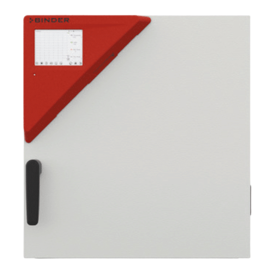
Mkf (e3.2)
alternating climate chambers with program control.
model version:mkf115-400v;mkf115-400v-c;mkf240-400v;mkf240-400v-c;mkf720-400v;mkf720-400v-c (115 pages)
Model version: bd056-230v;bd056ul-120v;bd115-230v;bd115ul-120v;bd260-230v;bd260ul-120v;bf056-230v;bf056ul-120v;bf115-230v;bf115ul-120v;bf260-230v;bf260ul-120v;ed056-230v;ed056ul-120v;ed115-230v;ed115ul-120v;ed260-230v;ed260ul-240v;fd056-230v;fd056ul-120v; (99 pages)
Cb (e6.1)
co2 - incubators
co2 – incubators with o2 control
with sterilizable ndir sensor system for co2
and microprocessor controller t4.12 (145 pages)
Model version:kbf115-230v;kbf115-240v;kbf240-230v;kbf240-240v;kbf720-230v;kbf720-240v;kbf1020-230v;kbf1020-240v;kmf115-230v;kmf115-240v;kmf240-230v;kmf240-240v;kmf720-230v;kmf720-240v.
constant climate chambers with program control.constant climate chamb (155 pages)
Content SAFETY ........................6 Personnel Qualification ........................6 Operating manual ..........................6 Legal considerations ........................... 6 1.3.1 Intellectual property ........................7 Structure of the safety instructions ...................... 7 1.4.1 Signal word panel ........................7 1.4.2 Safety alert symbol ........................8 1.4.3 Pictograms ..........................
Page 3
START UP ......................36 Turning on the chamber ........................36 Controller settings upon start up ....................... 36 Loading.............................. 37 SET-POINT ENTRY IN “FIXED VALUE” OPERATING MODE ......38 Set-point entry for temperature and fan speed through the “Setpoints” menu ......... 38 Adjusting the air flap position through the “Setpoints”...
Page 4
12. NOTIFICATION AND ALARM FUNCTIONS ............66 12.1 Notification and alarm messages overview ..................66 12.1.1 Notifications ..........................66 12.1.2 Alarm messages ........................67 12.2 State of alarm ............................ 67 12.3 Resetting an alarm, list of active alarms ................... 68 12.4 Tolerance range settings ........................
Page 5
20.1 General information, personnel qualification................... 109 20.2 Maintenance intervals, service ......................109 20.3 Simple troubleshooting ........................110 20.4 Sending the chamber back to BINDER GmbH ................112 21. DISPOSAL......................113 21.1 Disposal of the transport packing ....................113 21.2 Decommissioning ..........................113 21.3 Disposal of the chamber in the Federal Republic of Germany ............
35 U.S.C. § 287(a). Products and services listed on the BINDER website may be sold individually or as part of a combination product. Additional patent applications may also be pending in the U.S.
NOTICE Indicates a potentially hazardous situation which, if not avoided, may result in damage to the product and/or its functions or of a property in its proximity. 1.4.2 Safety alert symbol Use of the safety alert symbol indicates a risk of injury. Observe all measures that are marked with the safety alert symbol in order to avoid death or injury.
On chamber rear next to the exhaust duct • Figure 1: Position of labels on the chamber front (example: M 56) Keep safety labels complete and legible. Replace safety labels that are no longer legible. Contact BINDER Service for these replacements. M (E3.1) 1/2023 page 9/136...
MADE IN GERMANY www.binder-world.com Figure 2: Type plate (example M 115 regular chamber) Indications of the type plate (example) Indication Information BINDER Manufacturer: BINDER GmbH M 115 Model designation Drying and heating oven Chamber name: Drying and heating oven Serial No. 000000000000...
(for Germany: DGUV guidelines 213-850 on safe working in laborato- ries, issued by the employers’ liability insurance association). BINDER GmbH is only responsible for the safety features of the chamber provided skilled electricians or qualified personnel authorized by BINDER perform all maintenance and repair, and if components relating to chamber safety are replaced in the event of failure with original spare parts.
Page 12
The chambers do not dispose of any measures of explosion protection. DANGER Danger of explosion due to introduction of flammable or explosive substances in the chamber. Serious injury or death from burns and / or explosion pressure. ∅ Do NOT introduce any substance into the chamber which is combustible or explosive at working temperature.
Such ingredients include in particular acids and halides. Any corrosive damage caused by such ingredients is excluded from liability by BINDER GmbH. The chamber does not dispose of any measures of explosion protection.
Medical devices The chambers are not classified as medical devices as defined by Regulation (EU) No 2017/745. Due to the special demands of the Medical Products legislation, these chambers are not qualified to perform sterilization of medical devices as defined by Regulation (EU) No 2017/745.
1.11 Residual Risks The unavoidable design features of a chamber, as well as its proper field of application, can also pose risks, even during correct operation. These residual risks include hazards which, despite the inherently safe de- sign, existing technical protective equipment, safety precautions and supplementary protective measures, cannot be ruled out.
• Inappropriate repairs which do not meet the quality standard specified by BINDER • Use of replacement parts other than BINDER original replacement parts • Electrical safety analysis not performed after repairs 1.12 Operating instructions Depending on the application and location of the chamber, the operator of the chamber must provide the relevant information for safe operation of the chamber in a set of operating instructions.
COM™ 4 Multi Management Software (option, chap. 18.1). The chamber comes equipped with an Ethernet serial interface for computer communication. In addition, the BINDER APT-COM™ 4 Multi Management Software permits networking up to 100 chambers and connecting them to a PC for controlling and program- ming, as well as recording and representing temperature data.
Chamber overview Figure 4: Overview, closed chamber with single door Figure 5: Overview, open chamber with single door Triangular instrument panel with MB2 controller and USB interface Door handle Outer door On/Off switch (up to size 115), with M 260 cover without function Rack M (E3.1) 1/2023 page 18/136...
” (option) for optional analog output ANALOG OUTPUT Miniature fuses 250 V AC (T) (up to size 115): 2x 10 A for M 56 und 2x 12,5A for M 115 Connection for IEC connector plug (up to size 115) 230 V AC (10) Exhaust duct M (E3.1) 1/2023...
Triangular instrument panel 5,7" controller display with touchscreen USB interface Pilot lamp Figure 7: Instrument panel with MB2 program controller and USB interface Main power switch (sizes 260 and 720) The chambers sizes 260 and 720 are equipped with a main power (11) switch located on the chamber rear. Figure 8: Main power switch (11) on the M 260 and 720 chamber rear Zero-voltage switching contact The chambers are regularly equipped with a zero-voltage switching contact.
Note on second-hand chambers (Ex-Demo-Units): Second-hand chambers are chambers that have been used for a short time for tests or exhibitions. They are thoroughly tested before resale. BINDER ensures that the chamber is technically sound and will work flawlessly. Second-hand chambers are marked with a sticker on the chamber door. Please remove the sticker before commissioning the chamber.
• Permissible ambient temperature range during transport: -10 °C to +60 °C / 14 °F to 140 °F. You can order transport packing and pallets for transportation purposes from BINDER Service. Storage Intermediate storage of the chamber is possible in a closed and dry room. Observe the guidelines for tem- porary decommissioning (chap.
Page 23
Do not install or operate the chamber in potentially explosive areas. DANGER Danger of explosion due to combustible dusts or explosive mixtures in the vicinity of the chamber. Serious injury or death from burns and / or explosion pressure. ∅ Do NOT operate the chamber in potentially explosive areas. ...
• Only use original connection cables from BINDER according to the above specification. Prior to connection and start-up, check the power supply voltage. Compare the values to the specified •...
Connection to an exhaust/ventilation system (optional) Active suction from the chamber must only be effected together with external air. Therefore, the chamber’s exhaust air duct shall not be immediately connected to an active exhaust system. When connecting to an active exhaust system, proceed as follows: •...
The MB2 program controller permits programming temperature cycles, and specifying fan speed and special controller functions for each program section. You can enter values or programs directly at the controller or use the APT-COM™ 4 Multi Management Software (option) specially developed by BINDER. Operating mode Temperature values...
Operating functions in normal display Current operating mode Text list for information icons Date, time, authorization level of the logged-in user, memory Quick setpoint entry Continue to next screen Back to Normal display Information Program start Setpoint entry Event list Display of active alarms Access to main menu Figure 12: Operating functions of the MB2 controller in normal display (example values)
Display views: Normal display, program display, chart-recorder display Press the Change view icon to toggle between normal display, program display and chart-re- corder display. Press the Normal display icon to return from program display and chart recorder display back to Normal display. Normal display (actual values / setpoint values) Program display (example: time program) Chart recorder display...
Controller icons overview Navigation icons in Normal display Icon Signification Function Access from Normal display to the main menu Main menu Alarm Access from Normal display to the list of active alarms Access from Normal display to the event list Event list Access from Normal display to the setpoint entry menu: set- Setpoint setting...
Page 30
Functional icons in the chart recorder display Icon Signification Function Show legend Show legend Hide legend Hide legend Switch between legend pages Switch legend Show the indications of temperature (A1), fan (A2), air flap (A3), Show indications “Door open” (B1), and “Idle mode” (B2) Hide the indications of temperature (A1), fan (A2), air flap (A3), Hide indications “Door open”...
Operating modes The MB2 program controller operates in the following operating modes: • Idle mode The controller is not functional, i.e., there is no heating or refrigeration. The fan is off. The chamber approximates ambient values. You can activate and deactivate this operating mode with the “Idle mode” control contact in Fixed value operating mode (chap.11.6.5), time program operation (chap.
Controller menu structure Use the navigation icons in the screen footer in Normal display to access the desired controller functions. Normal display The available functions depend on the current authorization level “Service”, “Admin” or “User” (chap. 14.1). This is selected either during login or can be available without password protection. Main menu: program settings, further information, “Service”...
• Access to service data, controller reset to factory settings (chap. 5.5.3) • Available only for users with “Service” and “Admin” authorization level. Full functional range only for BINDER Service (users with “Service” authorization level). “Programs” submenu • Access to the controller’s program functions (chap. 9, 10, 11) M (E3.1) 1/2023...
5.5.3 “Service” submenu The “Service” submenu is available for users with “Service” or “Admin” authorization level. When logged-in with “Admin” authorization level the user will find information to tell the BINDER Service in service case. Path: Main menu > Service Serial number of the chamber, setup version chap.
Principle of controller entries In the selection and entry menus there are icons displayed in the footers which you can use to take over the entry or cancel it. Selection menu (example) Entry menu (example) After completing the settings there are the following possibilities: Press the Confirm icon to take over the entries and exit the menu or continue the menu se- quence.
To reduce odors quickly we recommend heating up the chamber to its nominal temperature for one day and in a well-ventilated location. WARNING: If customer should use a BINDER chamber running in non-supervised continu- ous operation, we strongly recommend in case of inclusion of irrecoverable specimen or samples to split such specimen or samples and store them in at least two chambers, if this is feasible.
Locked operation Provided that the user administration has been activated by the assignment of passwords for the different authorization types, the controller operation is first locked after turning on the unit, recognizable by the closed lock icon in the header. In the locked view the controller provides all display functions.
Idle Mode or Program Mode. Setting ranges Control ranges M 56, M 115: 22 ºC above ambient temperature up to 300 ºC / 572 °F 0.0 °C / 32 °F Temperature up to 300 ºC / 572 °F...
After completing the settings, press the Confirm icon to take over the entries and exit the menu, or press the Close icon to exit the menu without taking over the entries. Adjusting the air flap position through the “Setpoints” menu Opening the air flap in the exhaust duct serves to adjust the air change.
Direct setpoint entry via Normal display Alternatively you can also enter the setpoints for temperature and the fan speed, the air flap position and the switching-state of special controller functions directly via Normal display. Temperature setpoint entry Normal display. “Temperature” entry menu. Select the temperature setpoint.
Special controller functions via operation lines Press the Setpoint setting icon to access the “Setpoint” setting menu from Normal display. You can define the switching state of up to 16 operation lines (control contacts). They are used to activate / deactivate special controller functions. •...
Timer program: stopwatch function During an entered duration the controller constantly equilibrates to the setpoints entered in Fixed value operation mode (temperature, fan speed, configuration of the operation lines). This duration can be entered as a “Timer program”. During the program runtime, any setpoint changes do not become effective; the controller equilibrates to the values which were active during program start.
Stopping a running timer program 9.2.1 Pausing a running timer program Press the Program pause icon to interrupt the program. The program is paused. The program runtime stops running down, the time display flashes. There are the following options: Press the Program start icon to continue the program Press the Cancelling icon to cancel the program 9.2.2 Cancelling a running timer program Press the Program cancelling icon to cancel the program.
Time programs The MB2 program controller permits programming time programs with real-time reference. It offers 25 pro- gram memory positions with up to 100 program sections each. For each program section you can enter a temperature set-point, fan speed, section duration, type of tem- perature transition (ramp or step) and the tolerance range.
10.1.1 Performance during program delay time During the configured program delay time until program start, the controller equilibrates to the current set- points of Fixed value operation mode. Modifications of these setpoints are effective. When the configured moment for program start is reached, the program delay time ends and the program starts running. 10.2 Stopping a running time program 10.2.1 Pausing a running time program Press the Program pause icon to interrupt the program.
10.4 Creating a new time program Path: Main menu > Programs > Time program “Time program” menu: Enter the program name and, if desired, addi- overview of the existing programs. tional program information in the corresponding fields. Select an empty program place. Press the Confirm icon.
Program editor: “Edit program” menu Select the desired function and press the Confirm icon. The program editor offers following options: • Change the program name • Copy program • Replace program: Replacing a new or an existing program with the copied program. This menu point is visible only after a program has been copied.
10.6 Section editor: section management Path: Main menu > Programs > Time program Select the desired program. Section view (example: section 1). Program view. There are the following options: Select the desired program section (example: section 1) ...
10.6.1 Add a new program section Section editor: “Edit section” menu. Select “Create new section” and press the Con- firm icon. Then select whether to insert the new section be- fore or after the current section. Press the Confirm icon. The new section opens. 10.6.2 Copy and insert or replace a program section Section view (example: section 1).
Press the Edit icon to open the section editor if you want the current section to be replaced or the cop- ied section to be inserted before or after it Section view (example: section 1). Program view. Press the Edit icon to open the section editor Select the section to be replaced or before or after which the copied section shall be in- serted (example: section 2) and press the...
10.7 Value entry for a program section Path: Main menu > Programs > Time program Select the desired program and section. The section view gives access to all parameters of a program section. You can enter or modify the values. Program name and section number Section duration Type of setpoint transition: ramp or step...
10.7.2 Set-point ramp and set-point step You can define the type of temperature transitions for each individual program section. “Ramp” mode: Gradual changes of temperature The set-point of a given program section functions as the section’s start temperature. During the section’s duration, the set-point gradually passes to the set-point of the subsequent program section.
Section view. “Functions on/off” entry menu. Select the field “Functions on/off”. Mark / unmark the checkbox of the desired function to activate / deactivate it and press the Confirm icon. The controller returns to the section view. Section view indicating the operation lines. Activated operation line: switching status “1”...
10.7.5 Tolerance ranges For temperature, you can specify a tolerance range for each program section with different values for the tolerance minimum and maximum. When the actual value exceeds the given threshold, the program is interrupted. This is indicated on the display (see below). When the actual temperature is situated again within the entered tolerance limits, the program automatically continues.
Section view, showing the repetition function. • Select the field “Number of repetitions” and enter the desired number of repetitions. Setting range: 1 to 99, and -1 for infinite. Confirm entry with Confirm icon. The controller returns to the section view. •...
Week programs The MB2 program controller permits programming week programs with real-time reference. It offers 5 week program places in total with up to 100 shift points for each week program. Path: Main menu > Programs> Week program 11.1 Starting an existing week program In Normal display press the Program start icon to access the “Program start”...
11.3 Creating a new week program Path: Main menu > Programs > Week program Enter the program name and, if desired, addi- “Week program” menu: tional program information in the correspond- overview of the existing programs. ing fields. Select an empty program place. Select the set-point course “Ramp”...
11.4 Program editor: program management Path: Main menu > Programs > Week program “Week program” menu: Program view (example: program 1). overview of the existing programs. If a new program has been created, there is just Select an existing program (example: program one program section.
To add a new section, select “Create new Program view. section” and press the Confirm icon. With a new section no weekday is specified. There- The program view opens. fore, the section is first marked in red and cannot be saved.
11.5 Section editor: section management Path: Main menu > Programs > Week program Select the desired program. Program view. Section view (example: section 1). Select the desired program section There are the following options: (example: section 1) ...
11.5.1 Add a new program section Section editor: “Edit section” menu. Program view. Select “Create new section” and press the With a new section no weekday is specified. There- Confirm icon. fore, the section is first marked in red and cannot be saved.
Select “Replace section” to replace the selected sec- tion with the copied section Select “Insert section” to additionally add the copied section. Press the Confirm icon. If you selected “Insert section” the sections are auto- matically arranged in the correct chronological order. Section editor: “Edit section”...
“Change program name” menu. In the field “Course” select the desired setting “Ramp” or “Step” and press the Confirm icon. 11.6.2 Weekday In the field “Weekday” select the desired weekday. With “Daily” selected, this section will run every day at the same time. Section view.
11.6.4 Setpoint entry for temperature and fan speed, setting the air flap position • Select the field “Temperature” and enter the desired temperature setpoint. Setting range: 0 °C up to 300 °C Confirm entry with Confirm icon. The controller returns to the section view. •...
Notification and alarm functions 12.1 Notification and alarm messages overview 12.1.1 Notifications Notifications are indicated by information icons displayed in the screen header in Normal display An information icon serves as an indication of a certain condition. If this condition persists, in some cases an alarm will be triggered after a fix or configurable interval. As long as the condition persists, the information icon therefore continues to be displayed also in state of alarm.
12.1.2 Alarm messages Start after Zero-voltage relay Condition Alarm message condition occurred alarm output (option) The current actual temperature value “Temperature after configurable is outside the tolerance range (chap. time as alarm start range” time (chap. 12.4) 12.4) Open chamber door “Door open after 5 minutes ----...
12.3 Resetting an alarm, list of active alarms Door open Normal display in state of alarm (example). List of active alarms. Press the Alarm icon Press the Reset alarm icon. Pressing the Reset alarm icon mutes the buzzer for all active alarms. The icon then disappears. •...
After completing the settings, press the Confirm icon to take over the entries and exit the menu, or press the Close icon to exit the menu without taking over the entries. If there are actual values outside the tolerance range the following information icons for the corresponding parameter are displayed: Icon Signification...
When a defined cut-off temperature is reached, the overtemperature protective device turns off the heating. Cut-off temperature values: M 56: 330 °C / 626 °F M 115, M 260, M 720: 350 °C / 662 °F The message “Overtemperature” is displayed on the controller.
13.2 Overtemperature safety controller class 2 / 3.1 The chambers are regularly equipped with an adjustable electronic safety controller. It serves to protect the chamber, its environment and the contents against exceeding the maximum permissible temperature. Please observe the regulations applicable to your country (for Germany: DGUV guidelines 213-850 on safe working in laboratories, issued by the employers’...
13.2.1 Selecting between safety controller class 2 (temperature limiter) or class 3.1 You have the option of operating the safety controller with class 2 or 3.1 functionality. Path: Main menu > Settings > Various Submenu “Various”. • Select the field “Protecdtion class” and enter the desired class: „2“ (Klasse 2) oder „3“ (Klasse 3.1). Factory setting: class 3.
13.2.3 Setting the safety controller Press the Setpoint setting icon to access the “Setpoint” setting menu from Normal display. “Setpoints” menu. You can now set the safety controller mode and enter the safety controller value. Select the field “Safety controller” to access the settings.
Normal display with safety controller alarm. List of active alarms. Press the Reset alarm icon. Press the Alarm icon In the list of active alarms a text message indicates the alarm cause. If the audible arm is activated, the buzzer sounds. Press the Alarm icon icon to mute the buzzer. The alarm message “Safety controller alarm”...
13.3 Zero-voltage relay alarm contact Collective alarm output via the zero-voltage relay alarm contact The chamber is equipped at the rear with a zero-voltage relay contact (6), which permits the transmission of alarms generated by the chamber to an external monitoring system in order to monitor and record the alarm signals.
• All passwords can be changed in the “log out” submenu (chap. 14.3). “Service” authorization level • Authorization level only for BINDER service • Extensive authorization for controller operation and configuration, access to service data • The passwords for “Service”, “Admin” and “User” authorization levels can be changed in the “log out”...
Page 77
Operation after user login At user login, the authorization level is selected and confirmed by entering the respective pass- word. Following user login, controller operation is available, recognizable by the open-lock icon in the header. The available controller functions correspond to the user’s authorization level. Password protection activated for all levels: operation without user login is locked If passwords have been assigned for all au- thorization levels, the controller is locked with-...
Page 78
Information window To check the authorization level of the user currently logged-in, select in Normal display the arrow far right in the display header. The information window shows date and time, the controller’s free memory space and under “Authorization” the authorization level of the current user. If passwords have been assigned for all authorization levels, a user without login (password entry) has no authorization.
14.2 Log in Path: Main menu > User > Log in Controller with- out a user logged-in Selection of user type (example) All selection possibilities are password protected Controller with logged-in user After completing the settings, press the Confirm icon to take over the entries and exit the menu, or press the Close icon to exit the menu without taking over the entries.
14.3 Log out Path: Main menu > User > Log out User logoff with “Admin” authorization Controller without a Controller with user logged-in user logged-in User logoff with “User” authorization Controller without a Controller with user logged- logged-in user 14.4 User change If the password function has been deactivated (chap.14.5.2) this function is not available.
User selection (example) All selection possibilities are password protected Controller with logged- in user 14.5 Password assignment and password change This function is not available for a user logged-in with “User” authorization. 14.5.1 Password change A logged-in user can change the passwords of his current level and of the next lower level(s). Example: A user with “Admin”...
Page 82
Selection of the authorization level Enter desired password. If desired, press the Change (example: view with “Admin” authorization) keyboard icon to access other entry windows. In the “Keyboard switch” window you can select different keyboards to enter uppercase and lowercase letters, digits, and special characters.
14.5.2 Deleting the password for an individual authorization level A user logged-in with “Service” or “Admin” authorization can delete the passwords of his current level and of the next lower level(s). To do this no password is entered during a password change. Path: Main menu >...
14.5.3 New password assignment for “service” or “admin” authorization level when the password function was deactivated If the password protection for an authorization level has been deactivated, i.e., no password is assigned, no login for this level is possible. Therefore access to this authorization level is available without login. If the password for the “Service”...
14.6 Activation code Certain functions of the controller can be unlocked with a previously generated activation code. The activation code enables access to functions available only in the “Service” authorization level by users without a “Service” authorization. Such functions include e.g., adjustment or extended configurations. The activation code is available in authorization levels.
General controller settings Most of the general settings can be accessed in the “Settings” submenu, which is available for users with “Service” or “Admin” authorization level. It serves to enter date and time, select the language for the con- troller menus and the desired temperature unit and to configure the controller’s communication functions. 15.1 Selecting the controller’s menu language The MB2 program controller communicates by a menu guide using real words in German, English, French, Spanish, and Italian.
Page 87
Or later: Path: Main menu > Settings > Date and time “Date and time” submenu. “Date / time” entry menu. Select the field “Date / time”. Enter date and time and press the Confirm icon. “Date and time” submenu. “Date and time” submenu. In the field “Daylight saving time switch”...
15.3 Selecting the temperature unit Following start-up of the chamber: Or later: Path: Main menu > Settings > Chamber Select the desired temperature unit and press the Confirm icon. Change of the temperature unit between °C and °F. If the unit is changed, all values are converted accordingly C = degree Celsius 0 °C = 32 °F...
• Select the field “Brightness”. Move the grey slide to the left or right to define the brightness of the display • left = darker (minimum value: 0) • right = brighter (maximum value: 100) Press the Confirm icon. • Select the field “Wait time for screen saver” and enter the desired waiting time for the screen saver in seconds.
The waiting icon shows how much time there is left to touch the currently activated box. If the box is not touched withing this period, calibration is aborted and the display changes to Normal display. After completing the calibration, i.e., touching all four boxes, the display changes to Normal display. 15.5 Network and communication For these settings at least the “Admin”...
This controller menu serves to configure the web server. Then you can enter the chamber’s IP-address in the Internet. The IP address is available via Ethernet. The BINDER web server Chamber information > opens. Enter the user name and password which have been assigned for the web server in the controller menu.
15.5.3 E-Mail As soon as an alarm was triggered, an e-mail is sent to the configured e-mail address. Path: Main menu > Settings > Email E-mail address entry: “Email” submenu. Select the desired e-mail address field and enter the e-mail address. You can use the Keyboard change icon for entry.
15.6 USB menu: Data transfer via USB interface The USB port is located in the instrument box. When you insert a USB-stick, the “USB” menu opens. The USB stick must be formatted with FAT32 and have at least 8GB of memory. Depending on the user’s authorization level, different functions (highlighted in black) are available for the logged-in user.
General information 16.1 Service contact page Path: Main menu > Contact 16.2 Current operating parameters Press the Information icon to access the “Info” menu from Normal display. “Info” menu. Select the desired information. • Select “Program operation” to see information on a currently running program •...
(chap. 17.2) the Event list is cleared. 16.4 Technical chamber information Path: Main menu > Device info Chamber name and setup Versions of CPU, I/O module and safety for BINDER controller Service Information on digital and analog inputs for BINDER and outputs and phase angle outputs...
Chart recorder display This view offers graphic representation of the measurement course. Data representation imitates a chart recorder and allows recalling any set of measured data at any point of time taken from the recorded period. 17.1 Views Press the Change view icon to access the pen recorder display. 17.1.1 Show and hide legend Show legend Hide legend...
17.1.3 Show and hide specific indications Show indications Hide indications Press the Show indications icon to display the indications Temperature (A1), Fan (A2), Air flap (A3) or “Door open” (B1), and “Idle mode” (B2). Indications “Door open” (B1), and “Idle mode” (B2) are displayed.
Page 98
History display: Curve selection Curve selection Press the Curve selection icon to access the “Curve selection” submenu. “Curve selection” submenu. Select the curves to be displayed by checking the checkbox of the corresponding parameter. Press the Confirm icon History display: Search the required instant Search Press the Search icon to access the “Search”...
Page 99
History display: Zoom function Zoom Press the Zoom icon to access the “Zoom” submenu. “Zoom” submenu. Select the zoom factor and press the Confirm icon History display: Show and hide scroll buttons to scroll to an instant Show scroll buttons Hide scroll buttons Press the Show scroll buttons icon to access the “Page selection”...
17.2 Setting the parameters This menu allows setting the storage interval, the type of values to be shown and the scaling of the tem- perature charts. Path: Main menu > Settings > Measurement chart “Measurement chart” submenu. • Select the field “Storage interval” and enter the desired storage interval. Confirm entry with Confirm icon.
(sample values) The object temperature data are put out together with the data of the temperature controller and can be documented by the APT-COM™ 4 Multi Management Software (option, chap. 18.1) developed by BINDER. Technical data of the Pt100 sensor: •...
18.3 Object temperature control with flexible Pt100 temperature sensor (option) This function serves to ensure that the load will not become too hot due to the surrounding interior temper- ature while the target temperature inside the load has not yet been reached. For this purpose, the temperature setpoint is regulated in a way that it is achieved inside the load.
The object temperature data are put out together with the data of the temperature controller and can be documented by the APT-COM™ 4 Multi Management Software (option, chap. 18.1) developed by BINDER. Technical data of the Pt100 sensor: Three-wire technique •...
18.7 Inert gas connection with mostly gas-tight version (option) With this option the chamber is additionally sealed, so the loss when introducing inert gases is decreased. For details on the mostly gas-tight version please refer to chap. 18.6. The chamber is equipped with two ports for inert gas (nitrogen or noble gases). The ports are located on the top panel in the middle (A) and on the chamber rear at the bottom left (seen from the back) (B).
Page 105
Connection Observe the legal requirements and relevant standards and regulations for the safe handling of gas cylin- ders and inert gases. General information for safe handling of gas cylinders: • Store and use gas cylinders only in well ventilated areas. •...
Do NOT use a neutral cleaning agent on zinc coated surfaces. Do not use cleaning agents that may cause a hazard due to reaction with components of the device or the charging material. If there is doubt regarding the suitability of cleaning products, please contact BINDER service.
Page 107
We recommend using the neutral cleaning agent Art. No. 1002-0016 for a thorough cleaning. Any corrosive damage that may arise following use of other cleaning agents is excluded from liability by BINDER GmbH. Any corrosive damage caused by a lack of cleaning, is excluded from liability by BINDER GmbH. NOTICE Danger of corrosion by using unsuitable cleaners.
For chemical disinfection, we recommend using the disinfectant spray Art. No. 1002-0022. Any corrosive damage that may arise following use of other disinfectants is excluded from lia- bility by BINDER GmbH. With every decontamination / disinfection method, always use adequate personal safety con- trols.
For personnel requirements please refer to the Service Manual. • Repair Repair of the chamber can be performed by BINDER Service or by BINDER qualified service partners or technicians, in accordance with the description in the Service Manual. After maintenance, the chamber must be tested prior to resuming operation.
If there are is a technical fault or shortcoming, take the chamber out of operation and inform BINDER Service. If you are not sure whether there is a technical fault, proceed ac- cording to the following list. If you cannot clearly identify an error or there is a technical fault, please contact BINDER Service.
Page 111
Main power switch turned off. Turn on the main power switch. Log in with the required higher au- Menu functions not available thorization or contact BINDER ser- Menu functions not available. with current authorization level. vice to obtain an activation code (chap.
20.4 Sending the chamber back to BINDER GmbH If you return a BINDER product to us for repair or any other reason, we will only accept the product upon presentation of an authorization number (RMA number) that has previously been issued to you. An au- thorization number will be issued after receiving your complaint either in writing or by telephone prior to your sending the BINDER product back to us.
According to Annex I of Directive 2012/19/EU of the European Parliament and of the Council on waste electrical and electronic equipment (WEEE), BINDER devices are classified as “monitoring and control instruments” (category 9) only intended for professional use“. They must not be disposed of at public col- lecting points.
(Elektro- und Elektronikgerätegesetz, ElektroG from 20 October 2015, BGBl. I p. 1739) or contact BINDER service who will organize taking back and disposal of the cham- ber according to the German national law for electrical and electronic equipment (Elektro- und El- ektronikgerätegesetz, ElektroG from 20 October 2015, BGBl.
Page 115
If your distributor is not able to take back and dispose of the chamber, please contact BINDER service. Certified companies disassemble waste (used) BINDER equipment in primary substances for recycling according to Directive 2012/19/EU. The devices must be free from toxic, infectious or radioactive sub- stances in order to eliminate any health hazards to the employees of the recycling companies.
December 1996 by TÜV CERT). All test equipment used is subject to the administration of measure- ment and test equipment that is also constituent part of the BINDER QM DIN EN ISO 9001 systems. They are controlled and calibrated to a DKD-Standard at regular intervals.
5mm x 20 mm. A fuse may be replaced only with a substitute of the same ratings. Refer to the technical data of the respective device type. Three-phase devices are equipped with an internal miniature circuit breaker. 22.4 M technical data Chamber size M 56 M 115 M 260 M 720 Exterior dimensions Width, net mm / inch 560 / 22.01...
Page 118
+22 °C +/- 3 °C / 71.6 °F +/- 5.4 °F and a power supply voltage fluctuation of +/-10%. Technical data is determined in accordance to BINDER Factory Standard Part 2:2015 and DIN 12880:2007. All indications are average values, typical for chambers produced in series. We reserve the right to change technical specifications at any time.
22.5 Equipment and options (extract) To operate the chamber, use only original BINDER accessories or accessories / components from third-party suppliers authorized by BINDER. The user is responsible for any risk arising from using unauthorized accessories. Standard equipment Microprocessor display program controller with digital display and touchscreen Disconnectable audible over-temperature alarm Temperature safety controller class 2 or 3.1 acc.
22.6 Accessories and spare parts (extract) BINDER GmbH is responsible for the safety features of the chamber only, provided skilled electricians or qualified personnel authorized by BINDER perform all maintenance and repair, and if components relating to chamber safety are replaced in the event of failure with original spare parts.
23.3 Certificate for the GS mark of conformity of the “Deutsche Gesetzliche Un- fallversicherung e.V.“ (German Social Accident Insurance) DGUV M (E3.1) 1/2023 page 129/136...
Contamination clearance certificate 24.1 For chambers located outside the USA and Canada Declaration with regard to safety and health Erklärung zur Sicherheit und gesundheitlichen Unbedenklichkeit The German Ordinance on Hazardous Substances (GefStofV), and the regulations regarding safety at the workplace, require that this form be filled out for all products that are returned to us, so that the safety and health of our employees can be warranted.
Page 132
Kind of transport / transporter / Transportweg/Spediteur: Transport by (means and name of transport company, etc.) Versendung durch (Name Spediteur o.ä.) ___________________________________________________________________________________ Date of dispatch to BINDER GmbH / Tag der Absendung an BINDER GmbH: ___________________________________________________________________________________ M (E3.1) 1/2023 page 132/136...
Page 133
We herewith commit ourselves and guarantee that we will indemnify BINDER GmbH for all damages that are a consequence of incomplete or incorrect information provided by us, and that we will exempt BINDER GmbH from eventual damage claims by third parties./ Wir versichern, dass wir gegenüber BINDER für jeden...
Please complete this form and the Customer Decontamination Declaration (next 2 pages) and attach the required pictures. E-mail to: IDL_SalesOrderProcessing_USA@binder-world.com After we have received and reviewed the complete information we will decide on the issue of a RMA num- ber. Please be aware that size specifications, voltage specifications as well as performance specifications are available on the internet at www.binder-world.us...
Page 135
Customer (End User) Decontamination Declaration Health and Hazard Safety declaration To protect the health of our employees and the safety at the workplace, we require that this form is com- pleted by the user for all products and parts that are returned to us. (Distributors or Service Organizations cannot sign this form) NO RMA number will be issued without a completed form.
Page 136
4.5 Shipping laws and regulations have not been violated. I hereby commit and guarantee that we will indemnify BINDER Inc. for all damages that are a con- sequence of incomplete or incorrect information provided by us, and that we will indemnify and hold harmless BINDER Inc.
Need help?
Do you have a question about the M 56 and is the answer not in the manual?
Questions and answers