Sign In
Upload
Manuals
Brands
Binder Manuals
Laboratory Equipment
MK 240
Binder MK 240 Manuals
Manuals and User Guides for Binder MK 240. We have
5
Binder MK 240 manuals available for free PDF download: Translation Of The Original Operating Manual, Operating Manual
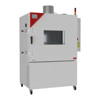
Binder MK 240 Translation Of The Original Operating Manual (173 pages)
Brand:
Binder
| Category:
Climate chamber
| Size: 8 MB
Table of Contents
Table of Contents
2
Safety
7
Personnel Qualification
7
Operating Manual
7
Legal Considerations
7
Structure of the Safety Instructions
8
Signal Word Panel
8
Safety Alert Symbol
8
Pictograms
9
Word Message Panel Structure
9
Localization / Position of Safety Labels on the Chamber
10
Type Plate
10
General Safety Instructions
11
Notes on the Installation Site
12
Notes on Loading and Operation
13
Notes on Handling CO
14
Notes on Handling Nitrogen When Using It as Inert Gas
15
Precautions When Handling Gas Cylinders
15
Intended Use
16
Use
16
EUCAR Hazard Levels - Overview
17
General Requirements for the Chamber Load
18
Tests with EUCAR Hazard Level up to Max. 3
18
Requirements for the Chamber Load
18
Operation with the Max. Expectation of an EUCAR Event with Hazard Level 3
19
Tests with EUCAR Hazard Level 4 to 6
19
Requirements for the Chamber Load
19
Detection and Secure Inclusion of an Event Within the Battery Test Chamber by Immanent
21
Cells with LIT MK 720)
21
Detection and Safe Inclusion of an Event Within the Battery Test Chamber by Additional Opera- Tor-Provided Measures with a Defined Load
21
Medical Devices
22
Personnel Requirements
22
Installation Site Requirements and Ambient Conditions
22
Foreseeable Misuse
23
Residual Risks
24
Operator Responsibility, Documentation, and Measures
27
Risk Assessment
27
Employee Training and Protocols
27
Operating Instructions
28
Protective Equipment
28
Standard Operating Procedures (Sops)
28
Testing and Maintenance
28
System Logbook
29
Operation Log
29
Testing
30
Objective of Testing
30
Scope of the Tests
30
Testing before Initial Commissioning
30
Tests of Technical Ventilation Systems, Extinguishing Systems, Gas Warning Devices, Inerting Devices, Devices, Protective Systems or Safety, Control or Regulating Devices, and Other Tech- Nical Devices for Explosion Protection
31
Inspection after Changes Requiring Review
32
Recurring Tests
32
Proof of Tests
32
Chamber Description
33
Manufacturer's Safety Plan: Protective Measures and Equipment
33
Chamber Overview
35
Safety Module on the Right Side of the Chamber
37
Lateral Control Panel
38
Rear Power Switch
39
Instrument Panel
39
Rear Chamber View
40
Gas Detection
41
CO 2 Fire Suppression Device (Can be Triggered Automatically and Manually)
43
Mechanical Door Lock
44
After Triggering of the CO
44
Automatic Triggering of the CO Fire Suppression Device
44
Fire Suppression Device
44
Exhaust Port with Reversible Pressure Relief Flap
45
Completeness of Delivery, Transportation, Storage, and Installation
46
Unpacking, and Checking Equipment and Completeness of Delivery
46
Guidelines for Safe Lifting and Transportation
47
Storage
47
Location of Installation and Ambient Conditions
47
Installation and Connections
49
Inertization Connections for Customer Systems
49
Connecting the CO Pressurized Gas Cylinder
49
Installation of the Voltage and Frequency Changer (Chambers with Voltage and Frequency Changer)
51
Electrical Connection
52
Information on Connecting the Battery Test Chamber
52
Connecting the Voltage and Frequency Changer (for Chambers Equipped with a Voltage and Frequency Changer)
53
Functional Overview of the Mb2 Chamber Controller
55
Operating Functions in Normal Display
56
Display Views: Normal Display, Program Display, Chart-Recorder Display
57
Controller Icons Overview
58
Operating Modes
60
Controller Menu Structure
61
Main Menu
62
Settings" Submenu
63
Service" Submenu
63
Principle of Controller Entries
64
Performance During and after Power Failures
64
Performance When Opening the Door
65
Commissioning
65
Preparing and Activating the General Safety Devices
65
Inserting the CO
65
Pressurized Gas Cylinder
65
Activating the Gas Detection System
66
Function Test of the Valve
67
Connection of the Coil Connector on the CO Pressurized Gas Cylinder
67
Connecting the CO 2 Flushing Line (High-Pressure Hose)
68
Commissioning an Operator-Provided Inertization
69
Handling the Safety Devices During Operation
70
Turning on the Chamber
70
Controller Settings Upon Start up
71
Set-Point Entry in "Fixed Value" Operating Mode
72
Set-Point Entry through the "Setpoints" Menu
72
Direct Setpoint Entry Via Normal Display
73
Special Controller Functions Via Operation Lines
73
Notification and Alarm Functions
75
Alarms Via Indicator Light with Integrated Buzzer
75
Connections and Forwarding of Notifications and Alarms to Customer Systems
76
Notification and Alarm Messages Overview on the MB2 Chamber Controller
77
Notifications
77
Alarm Messages
78
State of Alarm
78
Resetting an Alarm, List of Active Alarms
79
Activating / Deactivating the Audible Alarm (Alarm Buzzer) of the MB2 Controller
79
Behavior When/After Triggering of the Co Fire Suppression Device
80
Temperature Safety Devices
80
Over Temperature Protective Device (Class 1)
80
Temperature Limiter Class 2
81
Overtemperature Safety Controller
81
Safety Controller Modes
81
Setting the Safety Controller
82
Message and Measures in the State of Alarm
83
Function Check
83
Over/Under Temperature Safety Device Class 2 (Option)
84
Timer Program: Stopwatch Function
85
Starting a Timer Program
85
Performance During Program Delay Time
85
Stopping a Running Timer Program
86
Pausing a Running Timer Program
86
Cancelling a Running Timer Program
86
Performance after the End of the Program
86
Time Programs
87
Starting an Existing Time Program
87
Performance During Program Delay Time
88
Stopping a Running Time Program
88
Pausing a Running Time Program
88
Cancelling a Running Time Program
88
Performance after the End of the Program
88
Creating a New Time Program
89
Program Editor: Program Management
89
Deleting a Time Program
90
Section Editor: Section Management
91
Add a New Program Section
92
Copy and Insert or Replace a Program Section
92
Deleting a Program Section
93
Value Entry for a Program Section
94
Section Duration
94
Set-Point Ramp and Set-Point Step
95
Special Controller Functions Via Operation Lines
96
Setpoint Entry
97
Tolerance Range
98
Repeating One or Several Sections Within a Time Program
99
Saving the Time Program
99
Week Programs
100
Starting an Existing Week Program
100
Cancelling a Running Week Program
100
Creating a New Week Program
101
Program Editor: Program Management
102
Deleting a Week Program
103
Section Editor: Section Management
104
Add a New Program Section
105
Copy and Insert or Replace a Program Section
105
Deleting a Program Section
106
Value Entry for a Program Section
106
Set-Point Ramp and Set-Point Step Modes
106
Weekday
107
Start Time
107
Setpoint Entry
108
Special Controller Functions Via Operation Lines
108
User Management
109
Authorization Levels and Password Protection
109
Log in
112
Log out
113
User Change
113
Password Assignment and Password Change
114
Password Change
114
Deleting the Password for an Individual Authorization Level
116
New Password Assignment for "Service" or "Admin" Authorization Level When the Password Function was Deactivated
117
Activation Code
118
General Controller Settings
119
Selecting the Controller's Menu Language
119
Setting Date and Time
119
Selecting the Temperature Unit
121
Display Configuration
121
Adapting the Display Parameters
121
Touchscreen Calibration
122
Network and Communication
123
Serial Interfaces
123
Ethernet
124
Configuration
124
Display of MAC Address
125
Web Server
125
E-Mail
126
USB Menu: Data Transfer Via USB Interface
127
Turning off the Interior Lighting Automatically
128
General Information
128
Service Contact Page
128
Current Operating Parameters
129
Event List
130
Technical Chamber Information
130
Chart Recorder Display
131
Views
131
Show and Hide Legend
131
Switch between Legend
131
Show and Hide Specific Indications
132
History Display
132
Setting the Parameters
135
Notes on Refrigerating Operation
136
Anti-Condensation Protection Via Operation Line
137
Zero-Voltage Switching Outputs Via Operation Lines
138
Options
139
APT-COM™ 4 Multi Management Software (Option)
139
APT-COM™ 4 Basic Edition
139
RS485 Interface (Option)
139
Data Logger Kit (Option)
139
Analog Outputs for Temperature (Option)
140
Object Temperature Display with Flexible Pt 100 Temperature Sensor (Option)
140
Compressed Air Connection (Option)
141
Cleaning and Decontamination
141
Cleaning the Battery Test Chamber Following Normal Operation
142
Cleaning the Battery Test Chamber after Triggering of the CO
143
Fire Suppression Device
143
Decontamination / Chemical Disinfection
144
Maintenance: Inspection, Maintenance, Troubleshooting, Repair, Testing
145
General Information, Personnel Qualification
145
Maintenance Intervals, Service
146
Inspections
147
Simple Troubleshooting
147
Sending the Chamber Back to BINDER Gmbh
150
Disposal
150
Disposal of the Transport Packing
150
Decommissioning
151
Disposal of the Chamber in the Federal Republic of Germany
151
Disposal of the Chamber in the Member States of the EU Except for the Federal Republic of Ger- Many
152
Disposal of the Chamber in Non-Member States of the EU
154
Technical Description
154
Factory Calibration and Adjustment
154
Over-Current Protection
154
Definition of Usable Volume
154
Technical Data
155
Equipment and Options (Extract)
157
Accessories and Spare Parts (Extract)
158
Dimensions
159
Certificates and Declarations of Conformity
161
EU Declaration of Conformity
161
Certificate for the GS Mark of Conformity of the "Deutsche Gesetzliche Unfallversicherung E.V." (German Social Accident Insurance) DGUV
164
Safety Concept Certificate from TÜV SüD
166
Contamination Clearance Certificate
167
For Chambers Located Outside the USA and Canada
167
For Chambers Located in the USA and Canada
170
Advertisement
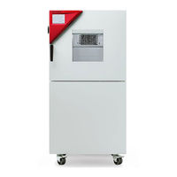
Binder MK 240 Operating Manual (165 pages)
Alternating climate chambers with program control
Brand:
Binder
| Category:
Climate chamber
| Size: 10 MB
Table of Contents
Table of Contents
2
Safety
6
Personnel Qualification
6
Operating Manual
6
Legal Considerations
6
Intellectual Property
7
Structure of the Safety Instructions
7
Signal Word Panel
7
Safety Alert Symbol
8
Pictograms
8
Word Message Panel Structure
9
Localization / Position of Safety Labels on the Chamber
9
Type Plate
10
General Safety Instructions on Installing and Operating the Chamber
11
Intended Use
13
Foreseeable Misuse
14
Residual Risks
15
Operating Instructions
16
Measures to Prevent Accidents
16
Chamber Description
17
Chamber Overview
18
Instrument Panel
18
Lateral Control Panel
19
Main Power Switch (MK 56)
20
Rear Power Switch (MK / MKT from Size 115 On)
20
Rear Chamber View
21
Completeness of Delivery, Transportation, Storage, and Installation
23
Unpacking, and Checking Equipment and Completeness of Delivery
23
Guidelines for Safe Lifting and Transportation
24
Storage
24
Location of Installation and Ambient Conditions
24
Installation and Connections
26
Connection of Cooling Water Outlet for Water Cooling (Option for MK 56)
26
Connection of Cooling Water Inlet for Water Cooling (Option for MK 56)
26
Installation of the Voltage and Frequency Changer (Chambers with Voltage and Frequency Changer)
27
Electrical Connection
28
Information on Connecting the Alternating Climate Chamber
28
Connecting the Voltage and Frequency Changer (for Chambers Equipped with a Voltage and Frequency Changer)
29
Functional Overview of the Mb2 Chamber Controller
31
Operating Functions in Normal Display
32
Display Views: Normal Display, Program Display, Chart-Recorder Display
33
Controller Icons Overview
34
Operating Modes
36
Controller Menu Structure
37
Main Menu
38
Settings" Submenu
39
Service" Submenu
39
Principle of Controller Entries
40
Performance During and after Power Failures
40
Performance When Opening the Door
41
Start up
41
Turning on the Chamber
41
Controller Settings Upon Start up
42
Set-Point Entry in "Fixed Value" Operating Mode
43
Set-Point Entry through the "Setpoints" Menu
43
Direct Setpoint Entry Via Normal Display
44
Special Controller Functions Via Operation Lines
44
Timer Program: Stopwatch Function
46
Starting a Timer Program
46
Performance During Program Delay Time
46
Stopping a Running Timer Program
47
Pausing a Running Timer Program
47
Cancelling a Running Timer Program
47
Performance after the End of the Program
47
Time Programs
48
Starting an Existing Time Program
48
Performance During Program Delay Time
49
Stopping a Running Time Program
49
Pausing a Running Time Program
49
Cancelling a Running Time Program
49
Performance after the End of the Program
49
Creating a New Time Program
50
Program Editor: Program Management
50
Deleting a Time Program
51
Section Editor: Section Management
52
Add a New Program Section
53
Copy and Insert or Replace a Program Section
53
Deleting a Program Section
54
Value Entry for a Program Section
55
Section Duration
55
Set-Point Ramp and Set-Point Step
56
Special Controller Functions Via Operation Lines
57
Setpoint Entry
58
Tolerance Range
59
Repeating One or Several Sections Within a Time Program
60
Saving the Time Program
60
Week Programs
61
Starting an Existing Week Program
61
Cancelling a Running Week Program
61
Creating a New Week Program
62
Program Editor: Program Management
63
Deleting a Week Program
64
Section Editor: Section Management
65
Add a New Program Section
66
Copy and Insert or Replace a Program Section
66
Deleting a Program Section
67
Value Entry for a Program Section
67
Set-Point Ramp and Set-Point Step Modes
67
Weekday
68
Start Time
68
Setpoint Entry
69
Special Controller Functions Via Operation Lines
69
Notification and Alarm Functions
70
Notification and Alarm Messages Overview
70
Notifications
70
Alarm Messages
71
State of Alarm
71
Resetting an Alarm, List of Active Alarms
72
Activating / Deactivating the Audible Alarm (Alarm Buzzer)
72
Temperature Safety Devices
73
Over Temperature Protective Device (Class 1)
73
Overtemperature Safety Controller Class 2
73
Safety Controller Modes
73
Setting the Safety Controller
74
Message and Measures in the State of Alarm
75
Function Check
75
Over/Under Temperature Safety Device Class 2 (Option)
76
User Management
77
Authorization Levels and Password Protection
77
Log in
80
Log out
81
User Change
81
Password Assignment and Password Change
82
Password Change
82
Deleting the Password for an Individual Authorization Level
84
New Password Assignment for "Service" or "Admin" Authorization Level When the Password Function was Deactivated
85
Activation Code
86
General Controller Settings
87
Selecting the Controller's Menu Language
87
Setting Date and Time
87
Selecting the Temperature Unit
89
Display Configuration
89
Adapting the Display Parameters
89
Touchscreen Calibration
90
Network and Communication
91
Serial Interfaces
91
Ethernet
92
Configuration
92
Display of MAC Address
93
Web Server
93
E-Mail
94
USB Menu: Data Transfer Via USB Interface
95
Turning off the Interior Lighting Automatically
96
General Information
96
Service Contact Page
96
Current Operating Parameters
97
Event List
98
Technical Chamber Information
98
Self-Test Function (MK 56)
99
Chart Recorder Display
101
Views
101
Show and Hide Legend
101
Switch between Legend
101
Show and Hide Specific Indications
102
History Display
102
Setting the Parameters
105
Notes on Refrigerating Operation
106
Anti-Condensation Protection Via Operation Line
107
Zero-Voltage Switching Outputs Via Operation Lines
108
Options
109
APT-COM™ 4 Multi Management Software (Option)
109
APT-COM™ 4 Basic Edition
109
Registration of the Multi Management Software APT-COM™ BASIC-Edition
109
RS485 Interface (Option)
109
Analog Outputs for Temperature (Option)
110
Object Temperature Display with Flexible Pt 100 Temperature Sensor (Option)
110
Compressed Air Connection (Option)
111
Compressed Air Dryer (Option)
111
Water Cooling (Option)
113
Cleaning and Decontamination
113
Cleaning
113
Decontamination / Chemical Disinfection
115
Maintenance and Service, Troubleshooting, Repair, Testing
116
General Information, Personnel Qualification
116
Maintenance Intervals, Service
117
Simple Troubleshooting
118
Sending the Chamber Back to BINDER Gmbh
121
Disposal
121
Disposal of the Transport Packing
121
Decommissioning
122
Disposal of the Chamber in the Federal Republic of Germany
122
Disposal of the Chamber in the Member States of the EU Except for the Federal Republic of Ger- Many
123
Disposal of the Chamber in Non-Member States of the EU
124
Technical Description
125
Factory Calibration and Adjustment
125
Over-Current Protection
125
Definition of Usable Volume
125
MK (E5) Technical Data
126
MKT (E5) Technical Data
128
Equipment and Options (Extract)
130
Accessories and Spare Parts (Extract)
131
MK Heating-Up and Cooling-Down Graphs
132
MKT Heating-Up and Cooling-Down Graphs
137
MK Heat Compensation
140
MKT Heat Compensation
142
Dimensions
144
Certificates and Declarations of Conformity
151
EU Declaration of Conformity for MK
151
EU Declaration of Conformity for MKT
154
Certificate for the GS Mark of Conformity of the "Deutsche Gesetzliche Unfallversicherung E.V." (German Social Accident Insurance) DGUV
157
Contamination Clearance Certificate
159
For Chambers Located Outside the USA and Canada
159
For Chambers Located in the USA and Canada
162
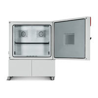
Binder MK 240 Operating Manual (159 pages)
Alternating climate chambers with program control; Alternating climate chambers with deep temperature and program control
Brand:
Binder
| Category:
Climate chamber
| Size: 10 MB
Table of Contents
Table of Contents
2
1 Safety
6
Legal Considerations
6
Structure of the Safety Instructions
6
Signal Word Panel
6
Safety Alert Symbol
7
Pictograms
7
Word Message Panel Structure
8
Localization / Position of Safety Labels on the Chamber
8
Type Plate
9
General Safety Instructions on Installing and Operating the Chamber
10
Intended Use
12
Operating Instructions
13
Measures to Prevent Accidents
13
2 Chamber Description
14
Chamber Overview
15
Instrument Panel
15
Lateral Control Panel
16
Main Power Switch (MK 56)
17
Rear Power Switch (MK / MKT 115, 240, 720)
17
Rear Chamber View
18
3 Completeness of Delivery, Transportation, Storage, and Installation
20
Unpacking, and Checking Equipment and Completeness of Delivery
20
Guidelines for Safe Lifting and Transportation
21
Storage
21
Location of Installation and Ambient Conditions
21
4 Installation and Connections
23
Connection of Cooling Water Outlet for Water Cooling (Option for MK 56)
23
Connection of Cooling Water Inlet for Water Cooling (Option for MK 56)
23
Installation of the Voltage and Frequency Changer (Chambers with Voltage and Frequency Changer)
24
Electrical Connection
26
Information on Connecting the Alternating Climate Chamber
26
Connecting the Voltage and Frequency Changer (for Chambers Equipped with a Voltage and Frequency Changer)
27
5 Functional Overview of the Mb2 Chamber Controller
28
Operating Functions in Normal Display
29
Display Views: Normal Display, Program Display, Chart-Recorder Display
30
Controller Icons Overview
31
Operating Modes
33
Controller Menu Structure
34
Main Menu
35
Settings" Submenu
36
Service" Submenu
36
Principle of Controller Entries
37
Performance During and after Power Failures
37
Performance When Opening the Door
38
6 Start up
38
Turning on the Chamber
38
Controller Settings Upon Start up
39
7 Set-Point Entry in "Fixed Value" Operating Mode
40
Set-Point Entry through the "Setpoints" Menu
40
Direct Setpoint Entry Via Normal Display
41
Special Controller Functions Via Operation Lines
41
8 Timer Program: Stopwatch Function
43
Starting a Timer Program
43
Performance During Program Delay Time
43
Stopping a Running Timer Program
44
Pausing a Running Timer Program
44
Cancelling a Running Timer Program
44
Performance after the End of the Program
44
9 Time Programs
45
Starting an Existing Time Program
45
Performance During Program Delay Time
46
Stopping a Running Time Program
46
Pausing a Running Time Program
46
Cancelling a Running Time Program
46
Performance after the End of the Program
46
Creating a New Time Program
47
Program Editor: Program Management
47
Deleting a Time Program
48
Section Editor: Section Management
49
Add a New Program Section
50
Copy and Insert or Replace a Program Section
50
Deleting a Program Section
51
Value Entry for a Program Section
52
Section Duration
52
Set-Point Ramp and Set-Point Step
53
Special Controller Functions Via Operation Lines
54
Setpoint Entry
55
Tolerance Range
56
Repeating One or Several Sections Within a Time Program
57
Saving the Time Program
57
10 Week Programs
58
Starting an Existing Week Program
58
Cancelling a Running Week Program
58
Creating a New Week Program
59
Program Editor: Program Management
60
Deleting a Week Program
61
Section Editor: Section Management
62
Add a New Program Section
63
Copy and Insert or Replace a Program Section
63
Deleting a Program Section
64
Value Entry for a Program Section
64
Set-Point Ramp and Set-Point Step Modes
64
Weekday
65
Start Time
65
Setpoint Entry
66
Special Controller Functions Via Operation Lines
66
11 Notification and Alarm Functions
67
Notification and Alarm Messages Overview
67
Notifications
67
Alarm Messages
68
State of Alarm
68
Resetting an Alarm, List of Active Alarms
69
Activating / Deactivating the Audible Alarm (Alarm Buzzer)
69
12 Temperature Safety Devices
70
Over Temperature Protective Device (Class 1)
70
Overtemperature Safety Controller Class 2
70
Safety Controller Modes
70
Setting the Safety Controller
71
Message and Measures in the State of Alarm
72
Function Check
72
Over/Under Temperature Safety Device Class 2 (Option)
73
13 User Management
74
Authorization Levels and Password Protection
74
Log in
77
Log out
78
User Change
78
Password Assignment and Password Change
79
Password Change
79
Deleting the Password for an Individual Authorization Level
81
New Password Assignment for "Service" or "Admin" Authorization Level When the Password Function was Deactivated
82
Activation Code
83
14 General Controller Settings
84
Selecting the Controller's Menu Language
84
Setting Date and Time
84
Selecting the Temperature Unit
86
Display Configuration
86
Adapting the Display Parameters
86
Touchscreen Calibration
87
Network and Communication
88
Serial Interfaces
88
Ethernet
89
Configuration
89
Display of MAC Address
90
Web Server
90
E-Mail
91
USB Menu: Data Transfer Via USB Interface
92
Turning off the Interior Lighting Automatically
93
15 General Information
93
Service Contact Page
93
Current Operating Parameters
94
Event List
95
Technical Chamber Information
95
Self-Test Function (MK 56)
96
16 Chart Recorder Display
98
Views
98
Show and Hide Legend
98
Switch between Legend
98
Show and Hide Specific Indications
99
History Display
99
Setting the Parameters
102
17 Notes on Refrigerating Operation
103
18 Anti-Condensation Protection Via Operation Line
104
19 Zero-Voltage Switching Outputs Via Operation Lines
105
20 Options
106
APT-COM™ 4 Multi Management Software (Option)
106
RS485 Interface (Option)
106
Data Logger Kit (Option)
106
Analog Outputs for Temperature (Option)
106
Compressed Air Connection (Option)
107
Compressed Air Dryer (Option)
107
Water Cooling (Option)
109
Object Temperature Display with Flexible Pt 100 Temperature Sensor (Option)
109
21 Maintenance, Cleaning, and Service
110
Maintenance Intervals, Service
110
Cleaning and Decontamination
111
Cleaning
111
Decontamination
113
Sending the Chamber Back to BINDER Gmbh
114
22 Disposal
114
Disposal of the Transport Packing
114
Decommissioning
115
Disposal of the Chamber in the Federal Republic of Germany
115
Disposal of the Chamber in the Member States of the EU Except for the Federal Republic of Germany
116
Disposal of the Chamber in Non-Member States of the EU
117
23 Troubleshooting
118
24 Technical Description
121
Factory Calibration and Adjustment
121
Over-Current Protection
121
Definition of Usable Volume
121
MK (E4) Technical Data
122
MKT (E4) Technical Data
124
Equipment and Options (Extract)
126
Accessories and Spare Parts (Extract)
127
MK Heating-Up and Cooling-Down Graphs
128
MKT Heating-Up and Cooling-Down Graphs
132
MK Heat Compensation
135
MKT Heat Compensation
136
Dimensions
138
25 Certificates and Declarations of Conformity
143
EU Declaration of Conformity for MK
143
EU Declaration of Conformity for MKT
146
Certificate for the GS Mark of Conformity of the "Deutsche Gesetzliche Unfallversicherung E.V." (German Social Accident Insurance) DGUV
149
26 Product Registration
151
Registering a BINDER Chamber
151
Multi Management Software APT-COM™ 4 BASIC-Edition
152
27 Contamination Clearance Certificate
153
For Chambers Located Outside the USA and Canada
153
For Chambers Located in the USA and Canada
156
Advertisement
Binder MK 240 Operating Manual (105 pages)
Model version: MK115-400V; MK115-400V-C; MK240-400V; MK240-400V-C; MK720-400V; MK720-400V-C; MKT115-400V; MKT115-400V-C; MKT240-400V; MKT240-400V-C; MKT720-400V; MKT720-400V-C
Brand:
Binder
| Category:
Laboratory Equipment
| Size: 8 MB
Table of Contents
Table of Contents
2
1 Safety
5
Legal Considerations
5
Structure of the Safety Instructions
5
Signal Word Panel
5
Safety Alert Symbol
6
Pictograms
6
Word Message Panel Structure
7
Localization / Position of Safety Labels on the Chamber
7
Type Plate
8
General Safety Instructions on Installing and Operating the Chamber
9
Intended Use
11
Operating Instructions
12
Measures to Prevent Accidents
12
2 Chamber Description
13
Chamber Overview
14
Lateral Control Panel
15
Instrument Panel
16
Rear Power Switch
16
3 Completeness of Delivery, Transportation, Storage, and Installation
17
Unpacking, and Checking Equipment and Completeness of Delivery
17
Guidelines for Safe Lifting and Transportation
18
Storage
18
Location of Installation and Ambient Conditions
18
4 Installation and Connections
20
Connection of Cooling Water Outlet for Water Cooling (Option)
21
Connection of Cooling Water Inlet for Water Cooling (Option)
21
Installation of the Voltage and Frequency Changer (Chambers with Voltage and Frequency Changer)22
22
Electrical Connection
23
Information on Connecting the Alternating Climate Chamber
23
Connecting the Voltage and Frequency Changer (for Chambers Equipped with a Voltage and Frequency Changer)
24
5 Start up
25
Function Overview of the MB1 Display Program Controller
25
Operating Modes
26
Performance after Power Failures
26
Performance When Opening the Door
26
Turning on the Chamber
27
6 Controller Mb1 Settings
28
Selection of the Menu Language
28
Overview of Program Controller MB1 Displays
29
Menu Settings in the "User-Settings" Menu
30
Menu Settings in the "User Level" Menu
31
7 Graphic Representation of the Historical Measurement (Chart Recorder Function)
32
Setting the Storage Rate
34
8 Manual Mode
35
Entering the Set-Point Values
35
Performance after Power Failure in Manual Mode
36
9 Program Operation
36
Menu-Based Program Entry
37
Selecting between Set-Point Ramp and Set-Point Step
39
Program Entry as Set-Point Ramp or as Set-Point Step
39
Information on Programming Different Temperature Transitions
44
Repetition of a Section or Several Sections Within a Program
45
Performance after Power Failure in Program Mode
45
Starting a Previously Entered Program
46
Deleting a Program
46
Temperature Profile and Operation Lines Template
47
Program Table Template
48
10 Bedew Protection Facility (Operation Line 1)
49
11 Zero-Voltage Relay Outputs Via Operation Lines 2 to 5 (Mkt, Option for Mk)
50
12 Temperature Safety Devices
51
Over-Temperature Protective Device (Class 1)
51
Safety Controller (Over-Temperature Safety Device Class 2)
51
Over/Under Temperature Safety Device Class 2 (Option)
53
13 Notification and Alarm Functions
54
Notification and Alarm System Overview (Auto Diagnosis System)
54
Resetting the Notifications or Alarm Messages
54
14 Notes on Refrigerating Operation
55
15 Options
56
Communication Software APT-COM™ 3 Datacontrolsystem (Option)
56
Interface RS 422 (Option)
56
Analog Outputs for Temperature (Option)
56
Data Logger Kit
57
Keyboard Locking (Option)
57
Compressed Air Dryer (Option)
58
Water Cooling (Available Via BINDER INDIVIDUAL Customized Solutions)
59
Additional Measuring Channel for Digital Object Temperature Indicator with Flexible Temperature Sensor Pt 100 (Option)
59
16 Maintenance, Cleaning, and Service
60
Maintenance Intervals, Service
60
Cleaning and Decontamination
61
Cleaning
61
Decontamination
62
Sending the Chamber Back to BINDER Gmbh
63
17 Disposal
64
Disposal of the Transport Packing
64
Decommissioning
64
Disposal of the Chamber in the Federal Republic of Germany
64
Disposal of the Chamber in the Member States of the EU Except for the Federal Republic of Germany
66
Disposal of the Chamber in Non-Member States of the EU
67
18 Troubleshooting
68
19 Technical Description
70
Factory Calibration and Adjustment
70
Over-Current Protection
70
Definition of Usable Volume
70
MK (E3.1) Technical Data
71
MKT (E3.1) Technical Data
73
Equipment and Options (Extract)
75
Accessories and Spare Parts (Extract)
76
Heating-Up and Cooling-Down Graphs MK
77
Heating-Up and Cooling-Down Graphs MKT
80
Heat Compensation MK
83
Heat Compensation MKT
84
Dimensions MK / MKT 115
86
Dimensions MK 240
87
Dimensions MKT 240
88
Dimensions MK / MKT 720
89
20 Certificates and Declarations of Conformity
90
EU Declaration of Conformity for MK (E3.1)
90
EU Declaration of Conformity for MKT (E3.1)
93
Certificate for the GS Mark of Conformity of the "Deutsche Gesetzliche Unfallversicherung E.V." (German Social Accident Insurance, DGUV)
96
21 Product Registration
98
22 Contamination Clearance Certificate
99
For Chambers Located Outside the USA and Canada
99
For Chambers Located in the USA and Canada
102
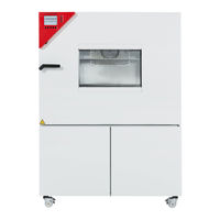
Binder MK 240 Operating Manual (65 pages)
TEMPERATURE TEST CHAMBERS FOR NATURAL SIMULATION WITH DISPLAY PROGRAM CONTROLLER MB1
Brand:
Binder
| Category:
Climate chamber
| Size: 2 MB
Table of Contents
Table of Contents
4
Safety
6
Legal Considerations
6
Structure of the Safety Instructions
6
Localization / Position of Safety Labels at the Unit
8
Type Plate
9
General Safety Instructions on Installing and Operating the Temperature Test Chamber for Natural Simulation MK
10
Intended Use
12
Unit Description
12
Unit Overview
13
Instrument Box MK
13
Lateral Control Panel MK
14
Scope of Delivery, Transportation, Storage, and Installation
15
Unpacking, and Checking Equipment and Scope of Delivery
15
Guidelines for Safe Lifting and Transportation
16
Storage
16
Location of Installation and Ambient Conditions
16
Installation and Connections
17
Electrical Connection
17
Start up
18
Function Overview of Screen Program Controller MB1
18
Operating Modes
18
Behavior after Power Failure
19
Switching on the Unit
19
Settings of the Controller Mb1
20
Selection of the Menu Language
20
Function Overview Program Controller MB1
21
Settings in the Menu "User-Settings
22
Settings in the Menu "User Level
23
Graphical Representation of the Measurement Course (Chart Recorder Function)
24
Setting the Storage Rate
26
Manual Mode
27
Set-Point Entry
27
Behavior after Power Failure in Manual Mode
28
Program Operation
28
Overview Menu-Based Program Entry
29
Selecting between Set-Point Ramp and Set-Point Step
31
Program Entry as Set-Point Ramp or as Set-Point Step
31
Advice for the Programming of the Different Temperature Transitions
34
Repetition of a Section or Several Sections Within a Program
35
Behavior after Power Failure in Program Mode
35
Starting a Previously Entered Program
36
Deleting a Program
36
Temperature Profile Template
37
Program Table Template
38
Bedew Protection Facility
39
Temperature Safety Devices
40
Over-Temperature Protective Device (Class 1)
40
Safety Controller (Over-Temperature Safety Device Class 2)
40
Over/Under Temperature Safety Device Class 2 (Option)
42
Notifying and Alarm Functions
43
Notifying and Alarm System Overview (Auto Diagnosis System)
43
Resetting the Notifying or Alarm Messages
43
Options
44
Communication Software APT-COM™ 3 Datacontrolsystem (Option)
44
Analog Output for Temperature (Option)
44
Keyboard Locking (Option)
44
Additional Measuring Channel for Digital Object Temperature Indicator with Flexible Temperature Sensor Pt 100 (Option)
45
Maintenance, Cleaning, and Service
45
Maintenance Intervals, Service
45
Cleaning and Decontamination
46
Sending Back the Unit to the BINDER Gmbh
47
Disposal
48
Disposal of the Transport Packing
48
Decommissioning
48
Disposal of the Unit in the Federal Republic of Germany
48
Disposal of the Unit in the Member States of the EC Except for the Federal Republic of Germany
50
Disposal of the Unit in Non-Member States of the EC
51
Troubleshooting
51
Technical Description
53
Factory Calibration and Adjustment
53
Over-Current Protection
53
Definition of Usable Space
53
Technical Data MK
54
Equipment and Options
55
Spare Parts
56
Heating-Up and Cooling-Down Graphs
57
Heat Compensation
58
Dimensions MK 53
59
Dimensions MK 240
60
Dimensions MK 720
61
Contamination Clearance Certificate
62
Advertisement
Related Products
Binder MK 115
Binder MKT 720
Binder MKT 115
Binder MK 720
Binder APT.line MK E2.1 Series
Binder MKF 400
Binder MKF 1020
Binder MKF400-400V
Binder MKF400-400V-C
Binder MKF1020-400V
Binder Categories
Climate chamber
Laboratory Equipment
Accessories
Oven
Farm Equipment
More Binder Manuals
Login
Sign In
OR
Sign in with Facebook
Sign in with Google
Upload manual
Upload from disk
Upload from URL