Binder MKT 240 Manuals
Manuals and User Guides for Binder MKT 240. We have 3 Binder MKT 240 manuals available for free PDF download: Operating Manual
Binder MKT 240 Operating Manual (165 pages)
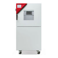
Alternating climate chambers with program control
Brand: Binder
|
Category: Climate chamber
|
Size: 10 MB
Table of Contents
Advertisement
Binder MKT 240 Operating Manual (159 pages)
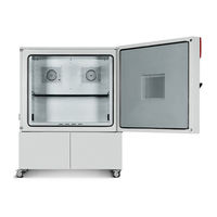
Alternating climate chambers with program control; Alternating climate chambers with deep temperature and program control
Brand: Binder
|
Category: Climate chamber
|
Size: 10 MB
Table of Contents
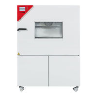
Binder MKT 240 Operating Manual (105 pages)
Model version:
MK115-400V;
MK115-400V-C;
MK240-400V;
MK240-400V-C;
MK720-400V;
MK720-400V-C;
MKT115-400V;
MKT115-400V-C;
MKT240-400V;
MKT240-400V-C;
MKT720-400V;
MKT720-400V-C
Brand: Binder
|
Category: Laboratory Equipment
|
Size: 8 MB
Table of Contents
Advertisement