Binder LIT MK 240 Translation Of The Original Operating Manual
Hide thumbs
Also See for LIT MK 240:
- Operating manual (165 pages) ,
- Operating manual (105 pages) ,
- Operating manual (159 pages)
Table of Contents
Advertisement
Quick Links
Operating Manual
Translation of the original operating manual
LIT MK (E5)
Battery test chambers
Model
Model version
LIT MK 240
LITMK240-400V
LITMK240-400V-C
LIT MK 720
LITMK720-400V
LITMK720-400V-C
BINDER GmbH
Address: Post office box 102, 78502 Tuttlingen, Germany Phone: +49 7462 2005 0
Fax: +49 7462 2005 100 Internet: http://www.binder-world.com
E-mail: info@binder-world.com Service Hotline: +49 7462 2005 555
Service Fax: +49 7462 2005 93 555 Service E-Mail: customerservice@binder-world.com
Service Hotline USA: +1 866 885 9794 or +1 631 224 4340 x3
Service Hotline Asia Pacific: +852 390 705 04 or +852 390 705 03
Service Hotline Russia and CIS: +7 495 988 15 16
Issue 03/2021
Art. No.
9020-0402, 9120-0402
9020-0404 (with voltage and frequency changer)
9020-0403, 9120-0403
9020-0405 (with voltage and frequency changer)
Art. no. 7001-0409
Advertisement
Table of Contents
Troubleshooting

Related Manuals for Binder LIT MK 240


Summary of Contents for Binder LIT MK 240
- Page 1 Fax: +49 7462 2005 100 Internet: http://www.binder-world.com E-mail: info@binder-world.com Service Hotline: +49 7462 2005 555 Service Fax: +49 7462 2005 93 555 Service E-Mail: customerservice@binder-world.com Service Hotline USA: +1 866 885 9794 or +1 631 224 4340 x3 ...
-
Page 2: Table Of Contents
Requirements for the chamber load ..................19 2.4.2 Detection and secure inclusion of an event within the battery test chamber by immanent safety with a defined load (max. one single 18650 cell with LIT MK 240, max. three 18650 cells with LIT MK 720)......................21 2.4.3 Detection and safe inclusion of an event within the battery test chamber by additional opera- tor-provided measures with a defined load ................ - Page 3 6.2.2 Tests of technical ventilation systems, extinguishing systems, gas warning devices, inerting devices, devices, protective systems or safety, control or regulating devices, and other tech- nical devices for explosion protection ..................31 6.2.3 Inspection after changes requiring review ................32 6.2.4 Recurring tests ........................
- Page 4 11.2 Commissioning an operator-provided inertization ................69 11.3 Handling the safety devices during operation ................... 70 11.4 Turning on the chamber ........................70 11.5 Controller settings upon start up ....................... 71 12. SET-POINT ENTRY IN “FIXED VALUE” OPERATING MODE ......72 12.1 Set-point entry through the “Setpoints”...
- Page 5 17.7.4 Setpoint entry .......................... 97 17.7.5 Tolerance range ........................98 17.7.6 Repeating one or several sections within a time program ............99 17.7.7 Saving the time program ......................99 18. WEEK PROGRAMS ................... 100 18.1 Starting an existing week program ....................100 18.2 Cancelling a running week program ....................
- Page 6 28.2 Maintenance intervals, service ......................146 28.3 Inspections ............................147 28.4 Simple troubleshooting ........................147 28.5 Sending the chamber back to BINDER GmbH ................150 29. DISPOSAL......................150 29.1 Disposal of the transport packing ....................150 29.2 Decommissioning ..........................151 29.3 Disposal of the chamber in the Federal Republic of Germany ............
-
Page 7: Safety
Operating Manual. This Operating Manual is supplemented and updated as needed. Always use the most recent version of the Operating Manual. When in doubt, call the BINDER Service Hotline for information on the up-to-date- ness and validity of this Operating Manual. -
Page 8: Structure Of The Safety Instructions
In no event shall BINDER be held liable for any damages, direct or incidental arising out of or related to the use of this manual. -
Page 9: Pictograms
1.4.3 Pictograms Warning signs Electrical hazard Hot surface Explosive atmosphere Stability hazard Risk of corrosion and / Lifting hazard Pollution Hazard Harmful substances or chemical burns Danger of frost Biohazard Mandatory action signs Lift with mechanical Disconnect the power Mandatory regulation Read operating assistance plug... -
Page 10: Localization / Position Of Safety Labels On The Chamber
Figure 1: Position of labels on the chamber Keep safety labels complete and legible. Replace safety labels that are no longer legible. Contact BINDER service for these replacements. Type plate The type plate sticks to the left side of the chamber, bottom right-hand, above the refrigerating module. -
Page 11: General Safety Instructions
BINDER GmbH is only responsible for the safety features of the chamber provided skilled electricians or qualified personnel authorized by BINDER perform all maintenance and repair, and if components relating to chamber safety are replaced in the event of failure with original spare parts. -
Page 12: Notes On The Installation Site
A function test is carried out on each safety module before delivery. To operate the chamber, use only original BINDER accessories or accessories from third-party suppliers authorized by BINDER. The user is responsible for any risk caused by using unauthorized accessories. 1.7.1 Notes on the installation site NOTICE Danger of overheating due to lack of ventilation. -
Page 13: Notes On Loading And Operation
∅ Do not carry out destructive tests (“abuse tests”). When testing 18650-type cells without customer-provided flushing/inertization, ensure that a maximum of one cell (LIT MK 240) / three cells (LIT MK 720) is inserted. When inserting several cells, ensure a minimum clearance between the individual cells. -
Page 14: Notes On Handling Co
Damage to lithium-ion batteries can lead to an atmosphere inside the battery test chamber that is harmful to health. DANGER Risk of occurrence of toxic gases due to damaged or burning cells/modules/sys- tems. Risk of self-ignition of cells, modules, or battery systems with flue gas (CO) development. -
Page 15: Notes On Handling Nitrogen When Using It As Inert Gas
The operator of plant-specific measures must observe the relevant country-specific regulations, which are intended to ensure safe handling of CO . Other national or international guidelines or the requirements of insurance companies or authorities must also be observed. In Germany, please pay particular attention to DGUV Information 205-026. -
Page 16: Intended Use
Secure the gas cylinders against falling and other mechanical damage. WARNING Risk of injury through sudden release of the stored pressure energy when the valve safety is torn off. Injuries. Secure gas cylinders against falling (chaining). Transport gas cylinders with a cylinder cart. The valve of the gas cylinder always must be closed before screwing on or unscrewing the gas hose. -
Page 17: Eucar Hazard Levels - Overview
Additional safety measures (flushing/inertization) may be connected by the operator. Gas connection facil- ities for inertization, as well as a pressure reducing valve and flow meter are provided by BINDER. Inertiza- tion can be used by a certain continuous flow or by regulation for oxygen suppression. The customer will be provided with the connections for the solenoid valve and the analog value of the oxygen sensor. -
Page 18: General Requirements For The Chamber Load
Such ingredients include in particular acids and hal- ides. Any corrosive damage caused by such ingredients is excluded from liability by BINDER GmbH. Contamination of the chamber by toxic, infectious or radioactive substances must be prevented... -
Page 19: Operation With The Max. Expectation Of An Eucar Event With Hazard Level 3
In the event that the user tests cells, modules, or systems with a higher energy content than that of an individual 18650 cell with LIT MK 240 or of three cells with LIT MK 720, the maximum expected damage to the test object may be consistent with EUCAR hazard level 3. - Page 20 Defined load (max. one single 18650 cell with LIT MK 240, max. three 18650 cells with LIT MK 720) Battery test chambers LIT MK offer with a defined load (max. one single 18650 cell with LIT MK 240, max. three 18650 cells with LIT MK 720), chap. 2.4.2) Sufficient security to securely include an event up to hazard level 6.
-
Page 21: Detection And Secure Inclusion Of An Event Within The Battery Test Chamber By Immanent
18650 cell (safety factor 3), LIT MK 720 can dissipate the energy of a max. three 18650 cells (safety factor 3),and any amount of gas released will be reliably below the LEL. Consequently, only a single individual cell (LIT MK 240) / three cells (LIT MK 720) of type 18650 may be inserted in this case. -
Page 22: Medical Devices
• The operator is responsible for compliance with the relevant regulations on the safety and instruction of personnel involved in the installation, installation, commissioning, operation, cleaning and decommis- sioning as well as maintenance and repair of the chamber as well as environmental protection. •... -
Page 23: Foreseeable Misuse
4 to 6 • Insertion of several cells with LIT MK 240 / of more than three cells with LIT MK 720 simultaneously into the chamber without customer rinsing/inertization during tests with EUCAR Hazard Levels 4 to 6 •... -
Page 24: Residual Risks
• Structural changes to the chamber without a subsequent risk assessment by the operator • Failure to observe the inspection and maintenance regulations (inspection before initial commissioning, recurring tests, inspection after maintenance or repairs, qualification of the tester) • Replacement of the CO compressed gas cylinder by untrained personnel •... - Page 25 Normal operation • Assembly errors • Loading error • Errors in user-side components (e.g. superordinate control system) • Operation of the chamber without continuous monitoring • Heating of the inserted accumulators above 90 °C • Contact with hot surfaces on the housing •...
- Page 26 • Absence of a plausibility check to rule out erroneous inscription of electrical components • Performance of repair work by untrained/insufficiently qualified personnel • Inappropriate repairs which do not meet the quality standard specified by BINDER • Use of replacement parts other than BINDER original replacement parts •...
-
Page 27: Operator Responsibility, Documentation, And Measures
Operator responsibility, documentation, and measures This is NOT an exhaustive list of the required measures and documents! Follow applicable national and international regulations. The chamber is intended for commercial use. The operator must know, comply with, and implement the relevant regulations on occupational safety. The operator must develop a complete safety concept and prepare a risk assessment. -
Page 28: Operating Instructions
The operator must instruct employees with regard to their activity before they begin using the chamber and related work equipment. Following this, further instruction must be provided at regular intervals, at least once per year. The date of each instruction and the names of the instructed persons must be recorded in writing. -
Page 29: System Logbook
System logbook Inspections with results and any measures taken, as well as measures taken for maintenance and repair, must be documented in a system logbook as written evidence. All events that occur during operation and all measures to safeguard operational readiness must be entered into the system logbook. -
Page 30: Testing
Testing Objective of testing The operator must have the system checked by an expert for proper function and safe condition. The objective is to determine the suitability and functionality of the safety measures. When testing the system, the safety concept must be evaluated and the target condition derived from it compared with the actual condition of the system (in accordance with the available test records): •... -
Page 31: Tests Of Technical Ventilation Systems, Extinguishing Systems, Gas Warning Devices, Inerting Devices, Devices, Protective Systems Or Safety, Control Or Regulating Devices, And Other Tech- Nical Devices For Explosion Protection
• Testing the plausibility of the safety plan and measures Verification of the traceability and plausibility of the safety plan and the measures derived from this in consideration of underlying constraints. The test does not apply to systems for which this test has already been carried out in the course of a permit or approval process. -
Page 32: Inspection After Changes Requiring Review
• Safety, control, or regulating devices to determine whether ventilation systems, gas warning devices, inerting devices ensure the proper functionality. • Connection elements and other technical devices (such as lightning protection, requirements for floors) with regard to their condition, their interconnections, and their installation / assembly for explosion safety (e.g. -
Page 33: Chamber Description
4 Multi Management Software (option, chap. 26.1). The chamber comes regularly equipped with an Ether- net serial interface for computer communication. In addition, the BINDER APT-COM™ 4 Multi Management Software (option) permits networking up to 100 chambers and connecting them to a PC for controlling and programming, as well as recording and representing temperature data. - Page 34 • Temperature monitoring Temperature monitoring by a rod controller (bimetal switch) is used to detect a temperature increase due to thermal run-through or fire. As soon as the threshold value of 120 °C is exceeded, message level 2 is triggered directly and the CO fire suppression system is activated.
-
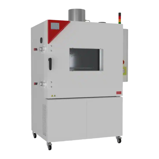
Page 35: Chamber Overview
Chamber overview Figure 3: Battery test chamber, front left view (example: LIT MK 240) Exhaust port with reversible pressure relief flap Instrument panel Mechanical door lock Door handle Refrigerating machine, maintenance access flaps Signal lamp Inspection window Chamber door MK LIT (E5) 01/2021... - Page 36 (10) (11) (12) Figure 4: Front right view with safety equipment (example LIT MK 240) Exhaust port with reversible pressure relief flap Mechanical door lock Door handle Signal lamp Manual trigger for CO fire suppression (flushing) (10) Main switch of the gas detection system and fire suppression system...
-
Page 37: Safety Module On The Right Side Of The Chamber
Safety module on the right side of the chamber (11a) (11b) (11c) (11d) (11e) Figure 5: Safety module (11) on the right side of the chamber (11a) Gas sensors for O / CO detection (chap. 7.8) (11b) Components of gas detection (chap. 7.8) and the inerting device (chap. 9.2) (11c) Monitoring device/alarm system (11d) Relay (11e) Evaluation unit of the gas sensors, output to analog outputs 4-20 mA... -
Page 38: Lateral Control Panel
Figure 6: Lateral control panel at the right side of the refrigerating machine, with options (13) Main power switch On/Off (16) Optional switch (BINDER Individual Customized Solutions) (14) Temperature safety device class 2 for over and under temperature (option): (17) -
Page 39: Rear Power Switch
Rear power switch This switch allows completely switching off the chamber (de-energized condition). (13) (21) Figure 7: Rear view LIT MK (13) Main power switch On / Off (21) Rear power switch Instrument panel 5,7" controller display with touchscreen USB interface Pilot lamp Figure 8: Triangle instrument panel with program controller MB2 and USB interface MK LIT (E5) 01/2021... -
Page 40: Rear Chamber View
Rear chamber view (23) (22) (21) Figure 9: LIT MK rear chamber view with optional compressed air connection (example: LIT MK 240) (21) Rear power switch (22) Power connection (23) Compressed air connection (option): Coupling connector to connect compressed air... -
Page 41: Gas Detection
Gas detection Gas detection is only active when the main switch (10) of the gas detection system is activated (ON position). Gas detection (measurement of atmospheric composition in the interior of the chamber) is used to deter- mine the start of a EUCAR hazard level 4 to 6 event. When predefined thresholds are reached, warnings or alarms are triggered via the alarm center (chap. - Page 42 Gas detection measuring principle Figure 11: Components of the gas detection Flow meter with ring initiator for measuring gas Flow meter with ring initiator for dilution air Gas sensor for O Gas sensor for H Gas sensor for CO Flow setting for readjusting Pump of the gas detection device MK LIT (E5) 01/2021 page 42/172...
-
Page 43: Co 2 Fire Suppression Device (Can Be Triggered Automatically And Manually)
7.9 CO fire suppression device (can be triggered automatically and manually) The CO fire suppression device includes a 5 kg pressurized CO gas cylinder for fire suppression. For installation, please refer to chap. 11.1). (10) Main switch (10) of the gas detection system and pressurized gas cylinder manual release (9) of the fire suppression device (example illustration) -
Page 44: Mechanical Door Lock
The CO fire suppression device can be triggered in four different ways: • Automatically via the alarm system (notification level 2) by gas detection. At least one programmed alarm threshold 2 threshold value for O / CO has been exceeded. To this end, the main switch for gas detection must be activated (ON position). -
Page 45: Exhaust Port With Reversible Pressure Relief Flap
7.11 Exhaust port with reversible pressure relief flap The chamber has a pressure relief flap with an internal diameter of 150 mm. This is equipped with a 250 mm outlet for connection to an exhaust system. The pressure relief flap is heated and is located at the top center of the chamber. It prevents pressure build- up by outgassing the cell(s). -
Page 46: Completeness Of Delivery, Transportation, Storage, And Installation
Note on second-hand chambers (Ex-Demo-Units): Second-hand chambers are chambers that were used for a short time for tests or exhibitions. They are thoroughly tested before resale. BINDER ensures that the chamber is technically sound and will work flaw- lessly. Second-hand chambers are marked with a sticker on the chamber door. Please remove the sticker before commissioning the chamber. -
Page 47: Guidelines For Safe Lifting And Transportation
Without the pallet the chamber is in imminent danger of overturning. • Permissible ambient temperature range during transport: -10 °C / 14 °F to +60 °C / 140 °F. You can order transport packing and pallets for moving or shipping purposes from BINDER service. Storage Intermediate storage of the chamber is possible in a closed and dry room. - Page 48 NOTICE Danger of overheating due to lack of ventilation. Damage to the chamber. ∅ Do NOT install the chamber in unventilated recesses. Ensure sufficient ventilation for dispersal of the heat. Observe the prescribed minimum distances when installing the chamber. Do not install or operate the chamber in potentially explosive areas.
-
Page 49: Installation And Connections
Permanent inertization of the test space displaces atmospheric oxygen and reduces the risk of ignition of combustible gases or vapors released by escaping or venting the cell(s) into the chamber. BINDER provides connections for this purpose. Figure 16: Inertization device components in the safety module... - Page 50 Figure 17: Connection for inert gas at the bottom of the safety module reduction The inert gas connection allows the operator to reduce the oxygen content in order to stay below the LEL. The settings for inertization are the responsibility of the operator. Gas connection for N permanent inertization (O suppression)
-
Page 51: Installation Of The Voltage And Frequency Changer (Chambers With Voltage And Frequency Changer)
Installation of the voltage and frequency changer (chambers with voltage and frequency changer) The voltage and frequency changer is supplied packed separately together with the battery test chamber. CAUTION Risk of injury and danger of damages by lifting heavy loads and by sliding or tilting of the voltage and frequency changer in case of improper lifting. -
Page 52: Electrical Connection
• Only use original connection cables from BINDER according to the above specification. • Prior to connection and start-up, check the power supply voltage. Compare the values to the specified data located on the chamber’s type plate (left chamber side, bottom right-hand, see chap. -
Page 53: Connecting The Voltage And Frequency Changer (For Chambers Equipped With A Voltage And Frequency Changer)
• Pollution degree (acc. to IEC 61010-1): 2 • Over-voltage category (acc. to IEC 61010-1): II See also electrical data (chap. 30.4). To completely separate the chamber from the power supply, you must disconnect the power plug. Install the chamber in a way that the power plug is easily accessible and can be easily pulled in case of danger. - Page 54 Left side of the voltage and frequency changer Right side of the voltage and frequency changer with connection socket (J) for the battery test chamber with power switch (K) and power cable (L) Figure 19: Voltage and frequency changer, mounted Figure 20: Power switch (K) of the voltage and frequency changer in position “ON”...
-
Page 55: Functional Overview Of The Mb2 Chamber Controller
The MB2 program controller permits programming temperature cycles and special controller functions for each program section. You can enter values or programs directly at the controller or use the APT-COM™ 4 Multi Management Software (option) specially developed by BINDER. Operating mode... -
Page 56: Operating Functions In Normal Display
10.1 Operating functions in normal display Current operating mode Text list for information icons Date, time, authorization level of the logged-in user, memory Quick setpoint entry Continue to next screen Back to Normal display Information Program start Setpoint entry Event list Display of active alarms Access to main menu Figure 22: Operating functions of the MB2 controller in normal display (sample values) -
Page 57: Display Views: Normal Display, Program Display, Chart-Recorder Display
10.2 Display views: Normal display, program display, chart-recorder display Press the Change view icon to toggle between normal display, program display and chart-re- corder display. Press the Normal display icon to return from program display and chart recorder display back to Normal display. -
Page 58: Controller Icons Overview
10.3 Controller icons overview Navigation icons in Normal display Icon Signification Function Access from Normal display to the main menu Main menu Alarm Access from Normal display to the list of active alarms Event list Access from Normal display to the event list Access from Normal display to the setpoint entry menu: setpoint Setpoint setting entry for Fixed value operation, safety controller settings... - Page 59 Functional icons in the chart recorder display Icon Signification Function Show legend Show legend Hide legend Hide legend Switch legend Switch between legend pages Show indications “Door open” (B1), “Anti-condensat.” (B2), “Com- Show indications pressed air” (B3) Hide indications “Door open” (B1), “Anti-condensat.” (B2), “Com- Hide indications pressed air”...
-
Page 60: Operating Modes
10.4 Operating modes The MB2 program controller operates in the following operating modes: • Idle mode The controller is not functional, i.e., there is no heating or refrigeration. The fan is off. The chamber approximates ambient values. You can activate and deactivate this operating mode with the “Idle mode” control contact in Fixed value operating mode (chap. -
Page 61: Controller Menu Structure
10.5 Controller menu structure Use the navigation icons in the screen footer in Normal display to access the desired controller functions. The available functions depend on the current authorization level “Service”, “Admin” or “User” (chap. 19.1). This is selected either during login or can be available without password protection. Main menu: program settings, further information, “Service”... -
Page 62: Main Menu
• Access to service data, controller reset to factory settings (chap. 10.5.3) • Available only for users with “Service” and “Admin” authorization level. Full functional range only for BINDER Service (users with “Service” authorization level). “Programs” submenu • Access to the controller’s program functions (chap. 13, 17, 18) -
Page 63: Settings" Submenu
10.5.3 “Service” submenu The “Service” submenu is available for users with “Service” or “Admin” authorization level. When logged-in with “Admin” authorization level the user will find information to tell the BINDER Service in service case. Path: Main menu > Service Serial number of the chamber, setup version chap. -
Page 64: Principle Of Controller Entries
10.6 Principle of controller entries In the selection and entry menus there are icons displayed in the footers which you can use to take over the entry or cancel it. Selection menu (example) Entry menu (example) After completing the settings there are the following possibilities: Press the Confirm icon to take over the entries and exit the menu or continue the menu se- quence. -
Page 65: Performance When Opening The Door
After closing the door, heating, refrigeration, and fan turn on again. Commissioning To ensure the effectiveness of all safety devices, commissioning should be carried out by BINDER Service. Ensure that commissioning is carried out by trained personnel with the necessary expertise. (see chap. 1.1) Ensure that the test is carried out and passed before initial commissioning (chap. -
Page 66: Activating The Gas Detection System
• Place the CO pressurized gas cylinder in the bracket provided and secure it with the strap. Securing the CO pressurized gas cylinder with Inserted and fixed CO pressurized gas cylinder the strap 11.1.2 Activating the gas detection system Switch on the activation switch of the gas detection system. Attention! When the gas detection system is activated via the main switch, the CO fire suppression device may be triggered automatically. -
Page 67: Function Test Of The Valve
In that case, the lock nut must not be removed under any circumstances. • If the valve does not close, it must be replaced. Contact BINDER Service. • If the valve is functioning correctly, screw the bleeder screw back in a gas-tight manner. -
Page 68: Connecting The Co 2 Flushing Line (High-Pressure Hose)
Bleeder screw Secured lever for manual release Filler neck Lock nut Valve outlet The high-pressure hose may only be connected after a successful test. DANGER Danger of suffocation and poisoning by leakage of CO in high concentration (> 4 Vol.-%). Death due to suffocation. -
Page 69: Commissioning An Operator-Provided Inertization
To release the higher-level control system, alarm threshold 1 of the O sensor can be set to the desired value (e.g. 4 Vol.% O ). To do this, contact BINDER Service. • If desired: Set alarm threshold 2 To do this, contact BINDER Service. -
Page 70: Handling The Safety Devices During Operation
The solenoid valve can be used to control the oxygen concentration An operator-provided control system can be connected to the “inertization solenoid valve” binary input to control flushing/inertization. Connection Connect the hose for the inert gas supply to the quick-release coupling at the bottom of the safety module (chap. -
Page 71: Controller Settings Upon Start Up
For control reasons the refrigeration machine starts with a delay time. The refrigeration ma- chine also turns off with a 5 minutes delay. This explains why the compressor may remain op- erating also during positive temperature jumps. 11.5 Controller settings upon start up The window “Language selection”... -
Page 72: Set-Point Entry In "Fixed Value" Operating Mode
Set-point entry in “Fixed value” operating mode In Fixed value operating mode you can enter a temperature set-point, and the switching-state of up to 16 operation lines. All settings made in Fixed value operating mode remain valid until the next manual change. They are saved also when turning off the chamber or in case of toggling to Idle Mode or Program Mode. -
Page 73: Direct Setpoint Entry Via Normal Display
12.2 Direct setpoint entry via Normal display Alternatively you can also enter the setpoints directly via Normal display. Example: “Temperature” entry menu. Normal display. Enter the desired setpoint and confirm entry Select the setpoint you want to change. with Confirm icon 12.3 Special controller functions via operation lines Press the Setpoint setting icon to access the “Setpoint”... - Page 74 Use the “Setpoints” menu to configure the operation lines. “Functions on/off” entry menu. “Setpoints” menu. Select the field “Functions on/off”. Mark / unmark the checkbox to activate / deacti- vate the desired function and press the Confirm icon Activated operation line: switching status “1” (On) Deactivated operation line: switching status “0”...
-
Page 75: Notification And Alarm Functions
Notification and alarm functions 13.1 Alarms via indicator light with integrated buzzer Audible and visual signals alert the user to different operating states. This alarm is independent of the chamber controller. The indicator light indicates three operating states as follows: Indicator light green, steady light signal •... -
Page 76: Connections And Forwarding Of Notifications And Alarms To Customer Systems
13.1.1 Connections and forwarding of notifications and alarms to customer systems The following signals are available to the customer for further processing: Terminal Signal Alarm threshold 1 O sensor (binary output) Analog signal for O sensor (4 - 20 mA) 0 vol.-% - 35 vol.-% (detection limit 2 vol.- 3-4 bridged Alarm threshold 1 H sensor (binary output) -
Page 77: Notification And Alarm Messages Overview On The Mb2 Chamber Controller
13.2 Notification and alarm messages overview on the MB2 chamber controller During normal operation (indicator light green), no notification regarding the LIT safety equipment is dis- played. 13.2.1 Notifications Notifications are indicated by information icons displayed in the screen header in Normal display An information icon serves as an indication of a certain condition. -
Page 78: Alarm Messages
“- - - - ” or Temperature sensor defective immediately “<-<-<” or “>->->” “Safety controller sen- Safety controller temperature sensor defective immediately sor” Fault in refrigerating machine. Contact BINDER ser- Compressor immediately vice. overcurrent Indicator light off LIT - Approval is immediately... -
Page 79: Resetting An Alarm, List Of Active Alarms
13.2.4 Resetting an alarm, list of active alarms List of active alarms. Normal display in state of alarm (example). Press the Reset alarm icon. Press the Alarm icon Pressing the Reset alarm icon mutes the buzzer for all active alarms. The icon then disappears. •... -
Page 80: Behavior When/After Triggering Of The Co Fire Suppression Device
14. Behavior when/after triggering of the CO fire suppression device When the chamber door is closed and the extraction system is connected, triggering the CO fire suppres- sion device does not endanger persons. Nevertheless, when the buzzer sounds and the red indicator light flashes, persons in the danger zone as defined by the operator must vacate the area and move to a safe place. -
Page 81: Temperature Limiter Class 2
When this temperature is reached, the heating, cooling and fan of the test cabinet are switched off and the appliance controller remains on. Resetting via a reset button not accessible to the user is always carried out by BINDER Service. The adjustable safety controller class 2 and optional safety devices class 2 remain functional and offer additional protection against excessive temperatures for the chamber. -
Page 82: Setting The Safety Controller
Example: Desired temperature value: 40 °C, desired safety controller value: 45 °C. Possible settings for this example: Temperature set point Safety controller mode Safety controller set-point Limit (absolute) 45 °C 40 °C Offset (relative) 5 °C 15.3.2 Setting the safety controller Press the Setpoint setting icon to access the “Setpoint”... -
Page 83: Message And Measures In The State Of Alarm
15.3.3 Message and measures in the state of alarm The state of alarm is indicated visually in Normal display by the alarm message “Safety controller alarm” and the screen header flashing in red color. If the buzzer is enabled (chap. 13.2.5) there is an additional audible alert (chap. -
Page 84: Over/Under Temperature Safety Device Class 2 (Option)
15.4 Over/under temperature safety device class 2 (option) The over-/under temperature safety device (14) consists of two entry mod- ules (14a) and (14b) located in the lateral control panel. Both modules can be set from -50 °C / -58°F up to 200 °C / 392°F and serve to define the maximum high and low temperature limits. -
Page 85: Timer Program: Stopwatch Function
Function check: Check the over/under temperature safety device class 2 at appropriate intervals for its functionality. It is recommended that the authorized operating personnel should perform such a check, e.g., before starting a longer work procedure. Timer program: stopwatch function During an entered duration the controller constantly equilibrates to the setpoints entered in Fixed value operation mode (temperature, configuration of the operation lines). -
Page 86: Stopping A Running Timer Program
16.2 Stopping a running timer program 16.2.1 Pausing a running timer program Press the Program pause icon to interrupt the program. The program is paused. The program runtime stops running down, the time display flashes. There are the following options: Press the Program start icon to continue the program Press the Cancelling icon to cancel the program 16.2.2 Cancelling a running timer program... -
Page 87: Time Programs
Time programs The MB2 program controller permits programming time programs with real-time reference. It offers 25 pro- gram memory positions with up to 100 program sections each. For each program section you can enter a temperature set-point, section duration, type of temperature transition (ramp or step) and the tolerance range. -
Page 88: Performance During Program Delay Time
17.1.1 Performance during program delay time During the configured program delay time until program start, the controller equilibrates to the current set- points of Fixed value operation mode. Modifications of these setpoints are effective. When the configured moment for program start is reached, the program delay time ends and the program starts running. 17.2 Stopping a running time program 17.2.1 Pausing a running time program Press the Program pause icon to interrupt the program.. -
Page 89: Creating A New Time Program
17.4 Creating a new time program Path: Main menu > Programs > Time program “Time program” menu: Enter the program name and, if desired, addi- overview of the existing programs. tional program information in the corresponding fields. Select an empty program place. Press the Confirm icon. -
Page 90: Deleting A Time Program
Program editor: “Edit program” menu Select the desired function and press the Confirm icon. The program editor offers following options: • Change the program name • Copy program • Replace program: Replacing an new or an existing program with the copied program. This menu point is visible only after a program has been copied. -
Page 91: Section Editor: Section Management
17.6 Section editor: section management Path: Main menu > Programs > Time program Select the desired program. Program view. Section view (example: section 1). Select the desired program section There are the following options: (example: section 1) ... -
Page 92: Add A New Program Section
17.6.1 Add a new program section Section editor: “Edit section” menu. Select “Create new section” and press the Confirm icon. Then select whether to insert the new section before or after the current section. Press the Confirm icon. The new section opens. 17.6.2 Copy and insert or replace a program section Section view (example: section 1). -
Page 93: Deleting A Program Section
Press the Edit icon to open the section editor if you want the current section to be replaced or the copied section to be inserted before or after it Section view (example: section 1). Program view. Select the section to be replaced or before or Press the Edit icon to open the section editor after which the copied section shall be inserted (example: section 2) and press the Confirm... -
Page 94: Value Entry For A Program Section
17.7 Value entry for a program section Path: Main menu > Programs > Time program Select the desired program and section. The section view gives access to all parameters of a program section. You can enter or modify the values. Program name and section number Section duration Type of setpoint transition: ramp or step... -
Page 95: Set-Point Ramp And Set-Point Step
17.7.2 Set-point ramp and set-point step You can define the type of temperature transitions for each individual program section. “Ramp” mode: Gradual changes of temperature The set-point of a given program section functions as the section’s start temperature. During the section’s duration, the set-point gradually passes to the set-point of the subsequent program section. -
Page 96: Special Controller Functions Via Operation Lines
“Ramp” and “Step” mode example (representation of a temperature course) W/°C t/min. Corresponding program table Duration Temperature Section No. Ramp or Step [hh:mm:ss] [°C] 00:10:00 40.0 Step 00:20:00 60.0 Step 00:10:00 80.0 Step 00:20:00 40.0 Step 00:10:00 40.0 Ramp 00:30:00 80.0 Ramp 00:30:00... -
Page 97: Setpoint Entry
Use the Section editor to configure the operation lines. “Functions on/off” entry menu. Section view. Mark / unmark the checkbox of the desired Select the field “Functions on/off”. function to activate / deactivate it and press the Confirm icon. The controller returns to the section view. Activated operation line: switching status “1”... -
Page 98: Tolerance Range
17.7.5 Tolerance range You can specify a temperature program tolerance range for each program section with different values for the tolerance minimum and maximum. When the actual value exceeds the given threshold, the program is interrupted. This is indicated on the display (see below). When the actual temperature is situated again within the entered tolerance limits, the program automatically continues. -
Page 99: Repeating One Or Several Sections Within A Time Program
17.7.6 Repeating one or several sections within a time program You can repeat several subsequent sections together. It is not possible to define the start section the same time also as the target section, therefore you cannot repeat a single individual section. Enter the desired number of repetitions in the field „Number of repetitions“... -
Page 100: Week Programs
Week programs The MB2 program controller permits programming week programs with real-time reference. It offers 5 week program places in total with up to 100 shift points for each week program. Path: Main menu > Programs> Week program 18.1 Starting an existing week program In Normal display press the Program start icon to access the “Program start”... -
Page 101: Creating A New Week Program
18.3 Creating a new week program Path: Main menu > Programs > Week program Enter the program name and, if desired, addi- “Week program” menu: tional program information in the correspond- overview of the existing programs. ing fields. Select an empty program place. Select the set-point course “Ramp”... -
Page 102: Program Editor: Program Management
18.4 Program editor: program management Path: Main menu > Programs > Week program “Week program” menu: Program view (example: program 1). overview of the existing programs. If a new program has been created, there is just one program section. Select an existing program (example: pro- gram 1). -
Page 103: Deleting A Week Program
Program view. To add a new section, select “Create new section” and press the Confirm icon. With a new section no weekday is specified. There- fore the section is first marked in red and cannot be The program view opens. saved. -
Page 104: Section Editor: Section Management
18.5 Section editor: section management Path: Main menu > Programs > Week program Select the desired program. Program view. Section view (example: section 1). Select the desired program section There are the following options: (example: section 1) ... -
Page 105: Add A New Program Section
18.5.1 Add a new program section Section editor: “Edit section” menu. Program view. Select “Create new section” and press the With a new section no weekday is specified. There- Confirm icon. fore the section is first marked in red and cannot be saved. -
Page 106: Deleting A Program Section
Select “Replace section” to replace the selected sec- tion with the copied section Select “Insert section” to additionally add the copied section. Press the Confirm icon. If you selected “Insert section” the sections are auto- matically arranged in the correct chronological order. Section editor: “Edit section”... -
Page 107: Weekday
“Change program name” menu. In the field “Course” select the desired setting “Ramp” or “Step” and press the Confirm icon. 18.6.2 Weekday In the field “Weekday” select the desired weekday. With “Daily” selected, this section will run every day Section view. at the same time. -
Page 108: Setpoint Entry
18.6.4 Setpoint entry • Select the field “Temperature” and enter the desired temperature setpoint. Setting range: -50 °C / -58°F up to 110 °C / 230 °F: Confirm entry with Confirm icon. The controller returns to the section view. 18.6.5 Special controller functions via operation lines You can define the switching state of up to 16 operation lines (control contacts). -
Page 109: User Management
• All passwords can be changed in the “log out” submenu (chap. 19.3). “Service” authorization level • Authorization level only for BINDER service • Extensive authorization for controller operation and configuration, access to service data • The passwords for “Service”, “Admin” and “User” authorization levels can be changed in the “log out”... - Page 110 Operation after user login At user login, the authorization level is selected and confirmed by entering the respective pass- word. Following user login, controller operation is available, recognizable by the open-lock icon in the header. The available controller functions correspond to the user’s authorization level. Password protection activated for all levels: operation without user login is locked If passwords have been assigned for all authori- zation levels, the controller is locked without reg-...
- Page 111 Information window To check the authorization level of the user currently logged-in, select in Normal display the arrow far right in the display header. The information window shows date and time, the controller’s free memory space and under “Authorization” the authorization level of the current user. If passwords have been assigned for all authorization levels, a user without login (password entry) has no authorization.
-
Page 112: Log In
19.2 Log in Path: Main menu > User > Log in Controller with- out a user logged-in Selection of user type (example) All selection possibilities are password protected Controller with logged-in user After completing the settings, press the Confirm icon to take over the entries and exit the menu, or press the Close icon to exit the menu without taking over the entries. -
Page 113: Log Out
19.3 Log out Path: Main menu > User > Log out User logoff with “Admin” authorization Controller without a Controller with user logged- logged-in user User logoff with “User” authorization Controller without a Controller with user logged- logged-in user 19.4 User change If the password function has been deactivated (chap.19.5.2) this function is not available. -
Page 114: Password Assignment And Password Change
User selection (example) All selection possibilities are password protected Controller with logged-in user 19.5 Password assignment and password change This function is not available for a user logged-in with “User” authorization. 19.5.1 Password change A logged-in user can change the passwords of his current level and of the next lower level(s). Example: A user with “Admin”... - Page 115 Selection of the authorization level Enter desired password. If desired, press the Change (example: view with “Admin” authorization) keyboard icon to access other entry windows. In the “Keyboard switch” window you can select different keyboards to enter uppercase and lowercase letters, digits, and special characters.
-
Page 116: Deleting The Password For An Individual Authorization Level
19.5.2 Deleting the password for an individual authorization level A user logged-in with “Service” or “Admin” authorization can delete the passwords of his current level and of the next lower level(s). To do this no password is entered during a password change. Path: Main menu >... -
Page 117: New Password Assignment For "Service" Or "Admin" Authorization Level When The Password Function Was Deactivated
19.5.3 New password assignment for “Service” or “Admin” authorization level when the password function was deactivated If the password protection for an authorization level has been deactivated, i.e., no password is assigned, no login for this level is possible. Therefore access to this authorization level is available without login. If the password for the “Service”... -
Page 118: Activation Code
19.6 Activation code Certain functions of the controller can be unlocked with a previously generated activation code. The activation code enables access to functions available only in the “Service” authorization level by users without a “Service” authorization. Such functions include e.g., adjustment or extended configurations. The activation code is available in authorization levels. -
Page 119: General Controller Settings
General controller settings Most of the general settings can be accessed in the “Settings” submenu, which is available for users with “Service” or “Admin” authorization level. It serves to enter date and time, select the language for the con- troller menus and the desired temperature unit and to configure the controller’s communication functions. 20.1 Selecting the controller’s menu language The MB2 program controller communicates by a menu guide using real words in German, English, French, Spanish, and Italian. - Page 120 Or later: Path: Main menu > Settings > Date and time “Date and time” submenu. “Date / time” entry menu. Select the field “Date / time”. Enter date and time and press the Confirm icon. “Date and time” submenu. “Date and time” submenu. In the field “Daylight saving time switch”...
-
Page 121: Selecting The Temperature Unit
20.3 Selecting the temperature unit Following start-up of the chamber: Or later: Path: Main menu > Settings > Chamber Select the desired temperature unit and press the Confirm icon. Change of the temperature unit between °C and °F. If the unit is changed, all values are converted accordingly C = degree Celsius 0 °C = 31°F... -
Page 122: Touchscreen Calibration
• Select the field “Brightness”. Move the grey slide to the left or right to define the brightness of the display • left = darker (minimum value: 0) • right = brighter (maximum value: 100) Press the Confirm icon. • Select the field “Wait time for screen saver” and enter the desired waiting time for the screen saver in seconds. -
Page 123: Network And Communication
This menu allows to configure the communication parameters of the RS485 interface. The device address is required to recognize chambers with this interface type in a network, e.g. when connecting it to the optional BINDER APT-COM™ 4 Multi Management Software (chap. 26.1). In this case do not change the other parameters. -
Page 124: Ethernet
20.5.2 Ethernet 20.5.2.1 Configuration Path: Main menu > Settings > Ethernet “Ethernet” submenu. • In the field “IP address assignment” select the desired setting “Automatic (DHCP)“ or “Man- ual“. With selection “Manual” you can enter the IP- address, the subnet mask and the standard gateway manually. -
Page 125: Display Of Mac Address
This controller menu serves to configure the web server. Then you can enter the chamber’s IP-address in the Internet. The IP address is available via Ethernet. The BINDER web server Chamber information > opens. Enter the user name and password which have been assigned for the web server in the controller menu. -
Page 126: E-Mail
20.5.4 E-Mail As soon as an alarm was triggered, an e-mail is sent to the configured e-mail address. Path: Main menu > Settings > Email E-mail address entry: “Email” submenu. Select the desired e-mail address field and enter the e-mail address. You can use the Keybord change icon for entry. -
Page 127: Usb Menu: Data Transfer Via Usb Interface
20.6 USB menu: Data transfer via USB interface The USB port is located in the instrument box. When you insert a USB-stick, the “USB” menu opens. Depending on the user’s authorization level, different functions (highlighted in black) are available for the logged-in user. -
Page 128: Turning Off The Interior Lighting Automatically
20.7 Turning off the interior lighting automatically Press the Interior lighting icon to turn on and off the interior lighting. Additionally. you can define in this menu the interval after which the turned-on light will turn off automati- cally. Path: Main menu >... -
Page 129: Current Operating Parameters
21.2 Current operating parameters Press the Information icon to access the “Info” menu from Normal display. “Info” menu. Select the desired information. • Select “Program operation” to see information on a currently running program. • Select “Setpoints“ to see information on the entered setpoints and operation lines. -
Page 130: Event List
(chap. 22.2) the Event list is cleared. 21.4 Technical chamber information Path: Main menu > Device info Chamber name and setup Versions of CPU, I/O module and safety for BINDER controller Service Information on digital and analog inputs for BINDER and outputs and phase angle outputs... -
Page 131: Chart Recorder Display
Chart recorder display This view offers graphic representation of the measurement course. Data representation imitates a chart recorder and allows recalling any set of measured data at any point of time taken from the recorded period. 22.1 Views Press the Change view icon to access the pen recorder display. 22.1.1 Show and hide legend Show legend Hide legend... -
Page 132: Show And Hide Specific Indications
22.1.3 Show and hide specific indications Show indications Hide indications Press the Show indications icon to display the indications “Door open” (B1), “Anti-condensat.” (B2), “Com- pressed air” (B3). Indications “Door open” (B1), “Anti-condensat.” (B2), and “Compressed air” (B3) are displayed. 22.1.4 History display History display Press the History display icon to change to the history display. - Page 133 History display: Curve selection Curve selection Press the Curve selection icon to access the “Curve selection” submenu. “Curve selection” submenu. Select the curves to be displayed by checking the checkbox of the corresponding parameter. Press the Confirm icon History display: Search the required instant Search Press the Search icon to access the “Search”...
- Page 134 History display: Zoom function Zoom Press the Zoom icon to access the “Zoom” submenu. “Zoom” submenu. Select the zoom factor and press the Confirm icon History display: Show and hide scroll buttons to scroll to an instant Show scroll buttons Hide scroll buttons Press the Show scroll buttons icon to access the “Page selection”...
-
Page 135: Setting The Parameters
22.2 Setting the parameters This menu allows setting the storage interval, the type of values to be shown and the scaling of the tem- perature charts. Path: Main menu > Settings > Measurement chart “Measurement chart” submenu. • Select the field “Storage interval” and enter the desired storage interval. Confirm entry with Confirm icon. -
Page 136: Notes On Refrigerating Operation
Notes on refrigerating operation Defrosting: BINDER battery test chambers are very diffusion-proof. To ensure high temperature precision there is no automatic cyclic defrosting device. The refrigerating system largely avoids icing of the evaporation plates. However, at very low temperatures the moisture in the air can condense on the evaporator leading to icing. -
Page 137: Anti-Condensation Protection Via Operation Line
Anti-condensation protection via operation line The anti-condensation protection condensates the chamber humidity at the coldest point in order to avoid the samples becoming wet from condensation. Anti-condensation protection is performed by the evaporator and can be programmed On/Off via operation line “Anti-condensation” in Fixed value and program modes. Use the anti-condensation protection only if absolutely necessary to prevent condensation on the charging material. -
Page 138: Zero-Voltage Switching Outputs Via Operation Lines
Zero-voltage switching outputs via operation lines The chambers are equipped optionally with four zero-voltage switching outputs (DIN sockets (17) and (18) located in the lateral control panel). The operation lines serve to switch any device connected to the zero-voltage relay output. They can be programmed On/Off in Fixed value and program modes. -
Page 139: Options
APT-COM™ 4 Basic Edition is included with the chamber. APT-COM™ 4 is available for download on the BINDER website. Upon registering the chamber, you will receive a license key with which you can activate the functionality of the Basic Edition for your downloaded version. -
Page 140: Analog Outputs For Temperature (Option)
Data Logger Kit T 220: Temperature range -90 °C / -130 °F up to +220 °C / 428 °F For detailed information on installation and operation of the BINDER Data Logger, please refer to the mounting instructions Art. No. 7001-0204 and to the original user manual of the manu- facturer, supplied with the data logger. -
Page 141: Compressed Air Connection (Option)
• Quality of the air: DIN ISO 8573-1:2010 [2:2:1] • Supply pressure: 6-8 bar domestic connection If a different connection pressure is required, please contact BINDER INDIVIDUAL Customized Solu- tions. • Permissible temperature: +10 °C / 50 °F up to +50 °C / 122 °F. -
Page 142: Cleaning The Battery Test Chamber Following Normal Operation
Do not use cleaning agents that may cause a hazard due to reaction with components of the device or the charging material. If there is doubt regarding the suitability of cleaning products, please contact BINDER service. We recommend using the neutral cleaning agent Art. No. 1002-0016 for a thorough and mild cleaning. -
Page 143: Cleaning The Battery Test Chamber After Triggering Of The Co
The neutral cleaning agent may cause health problems in contact with skin and if ingested. Follow the operating instructions and safety hints labeled on the bottle of the neutral clean- ing agent. Recommended precautions: To protect the eyes use sealed protective goggles. Wear gloves. Suitable pro- tective gloves in full contact with media: butyl or nitrile rubber, penetration time >480 minutes. -
Page 144: Decontamination / Chemical Disinfection
Any corrosive damage that may arise following use of other disinfectants is excluded from lia- bility by BINDER GmbH. Any corrosive damage caused by a lack of cleaning, is excluded from liability by BINDER GmbH. In case of contamination of the interior by biologically or chemically hazardous material, there are two pos- sible procedures depending on the type of contamination and charging material. -
Page 145: Maintenance: Inspection, Maintenance, Troubleshooting, Repair, Testing
Maintenance must be carried out at least once a year. See chap. 28.2. Maintenance can be carried out by BINDER Service or by BINDER qualified service partners or techni- cians in accordance with the description in the service manual. Refer to the service manual for personnel requirements. -
Page 146: Maintenance Intervals, Service
Testing before restarting after maintenance or repair as well as repeat tests according to the safety plan created by the operator is required. Testing of the chamber can be performed by BINDER Service or by BINDER qualified service partners or technicians, in accordance with the description in the Service Manual. -
Page 147: Inspections
If there are is a technical fault or shortcoming, take the chamber out of operation and inform BINDER Service. If you are not sure whether there is a technical fault, proceed ac- cording to the following list. If you cannot clearly identify an error or there is a technical fault, please contact BINDER Service. - Page 148 Chamber without function. Check chamber fuse and replace it if Chamber fuse has responded. appropriate. If it responds again, con- tact BINDER service. Controller defective. Nominal temperature ex- ceeded by 20 °C due to Contact BINDER service. chamber failure. Over temper- ature protective device (class 1) responds.
- Page 149 Menu functions not available Log in with the required higher au- Menu functions not available. with current authorization thorization or contact BINDER ser- level. vice to obtain an activation code. No access to controller Password incorrect. Contact BINDER service.
-
Page 150: Sending The Chamber Back To Binder Gmbh
28.5 Sending the chamber back to BINDER GmbH If you return a BINDER product to us for repair or any other reason, we will only accept the product upon presentation of an authorization number that has previously been issued to you. An authorization number (RMA number) will be issued after receiving your complaint either in writing or by telephone prior to your sending the BINDER product back to us. -
Page 151: Decommissioning
(Elektro- und Elektronikgerätegesetz, ElektroG from 20 October 2015, BGBl. I p. 1739) or contact BINDER service who will organize taking back and disposal of the cham- ber according to the German national law for electrical and electronic equipment (Elektro- und El- ektronikgerätegesetz, ElektroG from 20 October 2015, BGBl. -
Page 152: Disposal Of The Chamber In The Member States Of The Eu Except For The Federal Republic Of Ger- Many
According to Annex I of Directive 2012/19/EU of the European Parliament and of the Council on waste electrical and electronic equipment (WEEE), BINDER devices are classified as “monitoring and control instruments” (category 9) only intended for professional use“. They must not be disposed of at public col- lecting points. - Page 153 If your distributor is not able to take back and dispose of the chamber, please contact BINDER service. Certified companies disassemble waste (used) BINDER equipment in primary substances for recycling according to Directive 2012/19/EU. The devices must be free from toxic, infectious or radioactive sub- stances in order to eliminate any health hazards to the employees of the recycling companies.
-
Page 154: Disposal Of The Chamber In Non-Member States Of The Eu
(certified since December 1996 by TÜV CERT). All test equipment used is subject to the administration of measurement and test equipment that is also constituent part of the BINDER QM DIN EN ISO 9001 sys- tems. They are controlled and calibrated to a DKD standard at regular intervals. -
Page 155: Technical Data
The technical data refers to the so defined usable volume. Do NOT place samples outside this usable volume. Do NOT load this volume by more than half to enable sufficient airflow inside the chamber. Do NOT divide the usable volume into separate parts with large area samples. Do NOT place samples too close to each other in order to permit circulation between them and thus obtain a homogenous distribution of temperature. - Page 156 +22 °C +/- 3 °C / 71.6 °F +/- 5.4 °F and a power supply voltage fluctuation of +/-10%. Technical data is determined in accordance to BINDER Factory Standard Part 2:2015 and DIN 12880:2007. All indications are average values, typical for chambers produced in series. We reserve the right to change technical specifications at any time.
-
Page 157: Equipment And Options (Extract)
Internal socket 230 V AC, 1N ~ 50-60 Hz, max. load 500W, protection type IP 54 Ethernet interface for computer communication 1 access port with silicone plug, diameter 50 mm / 1.97 in left (LIT MK 240), 2 access ports with silicone plug, diameter 80 mm / 3.18 in left and right (LIT MK 720) -
Page 158: Accessories And Spare Parts (Extract)
30.6 Accessories and spare parts (extract) BINDER GmbH is responsible for the safety features of the chamber only, provided skilled electricians or qualified personnel authorized by BINDER perform all maintenance and repair, and if components relating to chamber safety are replaced in the event of failure with original spare parts. -
Page 159: Dimensions
30.7 Dimensions LIT MK 240 dimensions: [mm] MK LIT (E5) 01/2021 page 159/172... - Page 160 LIT MK 720 dimensions: [mm] MK LIT (E5) 01/2021 page 160/172...
-
Page 161: Certificates And Declarations Of Conformity
Certificates and declarations of conformity 31.1 EU Declaration of Conformity MK LIT (E5) 01/2021 page 161/172... - Page 162 MK LIT (E5) 01/2021 page 162/172...
- Page 163 MK LIT (E5) 01/2021 page 163/172...
-
Page 164: Certificate For The Gs Mark Of Conformity Of The "Deutsche Gesetzliche Unfallversicherung E.v." (German Social Accident Insurance) Dguv
31.2 Certificate for the GS mark of conformity of the “Deutsche Gesetzliche Un- fallversicherung e.V.“ (German Social Accident Insurance) DGUV MK LIT (E5) 01/2021 page 164/172... - Page 165 MK LIT (E5) 01/2021 page 165/172...
-
Page 166: Safety Concept Certificate From Tüv Süd
31.3 Safety concept certificate from TÜV Süd MK LIT (E5) 01/2021 page 166/172... -
Page 167: Contamination Clearance Certificate
Contamination clearance certificate 32.1 For chambers located outside the USA and Canada Declaration regarding safety and health Erklärung zur Sicherheit und gesundheitlichen Unbedenklichkeit The German Ordinance on Hazardous Substances (GefStofV), and the regulations regarding safety at the workplace, require that this form be filled out for all products that are returned to us, so that the safety and the health of our employees can be guaranteed. - Page 168 Kind of transport / transporter / Transportweg/Spediteur: Transport by (means and name of transport company, etc.) Versendung durch (Name Spediteur o.ä.) __________________________________________________________________________________ Date of dispatch to BINDER GmbH / Tag der Absendung an BINDER GmbH ___________________________________________________________________________________ MK LIT (E5) 01/2021 page 168/172...
- Page 169 We hereby commit ourselves and guarantee that we will indemnify BINDER GmbH for all damages that are a consequence of incomplete or incorrect information provided by us, and that we will exempt BINDER GmbH from eventual damage claims by third parties./ Wir versichern, dass wir gegenüber BINDER für jeden...
-
Page 170: For Chambers Located In The Usa And Canada
Please complete this form and the Customer Decontamination Declaration (next 2 pages) and attach the required pictures. E-mail to: IDL_SalesOrderProcessing_USA@binder-world.com After we have received and reviewed the complete information we will decide on the issue of a RMA num- ber. Please be aware that size specifications, voltage specifications as well as performance specifications www.binder-world.us... - Page 171 Customer (End User) Decontamination Declaration Health and Hazard Safety declaration To protect the health of our employees and the safety at the workplace, we require that this form is com- pleted by the user for all products and parts that are returned to us. (Distributors or Service Organizations cannot sign this form) NO RMA number will be issued without a completed form.
- Page 172 4.5 Shipping laws and regulations have not been violated. I hereby commit and guarantee that we will indemnify BINDER Inc. for all damages that are a con- sequence of incomplete or incorrect information provided by us, and that we will indemnify and hold harmless BINDER Inc.
Need help?
Do you have a question about the LIT MK 240 and is the answer not in the manual?
Questions and answers