Table of Contents
Advertisement
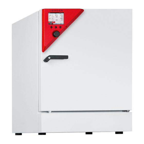
Operating Manual
CB (E6.1)
CO
- Incubators
2
CO
– Incubators with O
2
with sterilizable NDIR sensor system for CO
and microprocessor controller T4.12
Model
Voltage
CB 60
230 V
CB 60-UL
100-120V
CB 60
230 V
CB 60-UL
100-120V
CB 60
230 V
CB 60-UL
100-120V
CB 60
230 V
CB 60-UL
100-120V
CB 160 (E6)
230 V
CB 160-UL
100-120V
CB 160 (E6)
230 V
CB 160-UL
100-120V
CB 160
230 V
CB 160-UL
100-120V
CB 160
230 V
CB 160-UL
100-120V
CB 220
230 V
CB 220-UL
100-120V
CB 220
230 V
CB 220-UL
100-120V
CB 220
230 V
CB 220-UL
100-120V
CB 220
230 V
CB 220-UL
100-120V
BINDER GmbH
Address: Post office box 102, 78502 Tuttlingen, Germany Phone: +49 7462 2005 0
Fax: +49 7462 2005 100 Internet: http://www.binder-world.com
E-mail: info@binder-world.com Service Hotline: +49 7462 2005 555
Service Fax: +49 7462 2005 93 555 Service E-Mail: service@binder-world.com
Service Hotline USA: +1 866 885 9794 or +1 631 224 4340 x3
Service Hotline Asia Pacific: +852 390 705 04 or +852 390 705 03
Service Hotline Russia and CIS: +7 495 988 15 16
Issue 07/2017
2
Equipment
O
control
2
O
control
2
Divided inner door
Divided inner door
O
control
Divided inner door
2
O
control
Divided inner door
2
O
control
2
O
control
2
Divided inner door
Divided inner door
O
control
Divided inner door
2
O
control
Divided inner door
2
O
control
2
O
control
2
Divided inner door
Divided inner door
O
control
Divided inner door
2
O
control
Divided inner door
2
control
2
Art. No.
9040-0088, 9140-0088
9040-0089, 9140-0089
9040-0090, 9140-0090
9040-0091, 9140-0091
9040-0104, 9140-0104
9040-0105, 9140-0105
9040-0106, 9140-0106
9040-0107, 9140-0107
9040-0092, 9140-0092
9040-0093, 9140-0093
9040-0094, 9140-0094
9040-0095, 9140-0095
9040-0100, 9140-0100
9040-0101, 9140-0101
9040-0102, 9140-0102
9040-0103, 9140-0103
9040-0096, 9140-0096
9040-0097, 9140-0097
9040-0098, 9140-0098
9040-0099, 9140-0099
9040-0108, 9140-0108
9040-0109, 9140-0109
9040-0110, 9140-0110
9040-0111, 9140-0111
Art. No. 7001-0333
Advertisement
Table of Contents


Need help?
Do you have a question about the CB 60-UL and is the answer not in the manual?
Questions and answers