Table of Contents
Advertisement
Quick Links
Operating Manual
APT.line™ MK (E2.1)
Alternating climate chamber with program control
Model
MK 53 (E2.1)
BINDER GmbH
Address
Tel.
Fax
Internet
E-mail
Service Hotline
Service Fax
Service E-Mail
Service Hotline USA
Service Hotline Asia Pacific
Service Hotline Russia and CIS +7 495 988 15 16
Issue 10/2014
Art. No.
9020-0006, 9120-0006
Post office box 102
D-78502 Tuttlingen
+49 7462 2005 0
+49 7462 2005 100
http://www.binder-world.com
info@binder-world.com
+49 7462 2005 555
+49 7462 2005 93 555
service@binder-world.com
+1 866 885 9794 or +1 631 224 4340 x3
+852 390 705 04 or +852 390 705 03
Art. Nr. 7001-0028
Advertisement
Table of Contents

Related Manuals for Binder APT.line MK E2.1 Series


Summary of Contents for Binder APT.line MK E2.1 Series
- Page 1 Operating Manual APT.line™ MK (E2.1) Alternating climate chamber with program control Model Art. No. MK 53 (E2.1) 9020-0006, 9120-0006 BINDER GmbH Address Post office box 102 D-78502 Tuttlingen Tel. +49 7462 2005 0 +49 7462 2005 100 Internet http://www.binder-world.com E-mail info@binder-world.com...
-
Page 2: Ec - Declaration Of Conformity
EG – KONFORMITÄTSERKLÄRUNG EC - DECLARATION OF CONFORMITY CE - DECLARATION DE CONFORMITE Anbieter / Supplier / Fournisseur: BINDER GmbH Anschrift / Address / Adresse: Im Mittleren Ösch 5, D-78532 Tuttlingen Umweltsimulations-Schrank für klassische Temperaturprofile Produkt / Product / Produit:... - Page 3 Die oben beschriebenen Produkte sind konform mit folgenden harmonisierten Normen: The products described above are in conformity with the following harmonized standards: Les produits décrits ci-dessus sont conformes aux normes harmonisées suivantes: Sicherheit / safety / sécurité: EN 61010-1:2010 Sicherheitsbestimmungen für elektrische Mess-, Steuer-, Regel- und Laborgeräte –...
- Page 4 D-78532 Tuttlingen, 16.01.2013 BINDER GmbH B. Hofmann P. M. Binder Leiter F & E Geschäftsführender Gesellschafter Director R & D Managing Director Chef de service R&D Directeur général 3 / 3 MK (E2.1) 10/2014 page 4/73...
-
Page 5: Product Registration
Product registration MK (E2.1) 10/2014 page 5/73... -
Page 6: Table Of Contents
CONTENTS EC – Declaration of Conformity ........................2 Product registration ............................5 SAFETY ........................8 Legal considerations ........................... 8 Structure of the safety instructions ...................... 8 1.2.1 Signal word panel ........................8 1.2.2 Safety alert symbol ........................9 1.2.3 Pictograms ..........................9 1.2.4 Word message panel structure .................... - Page 7 15.2.1 Cleaning ........................... 53 15.2.2 Decontamination ........................54 15.3 Sending back the unit to the BINDER GmbH ..................55 16. DISPOSAL ......................56 16.1 Disposal of the transport packing ...................... 56 16.2 Decommissioning ..........................56 16.3 Disposal of the unit in the Federal Republic of Germany ..............56 16.4 Disposal of the unit in the member states of the EC except for the Federal Republic of Germany ..
-
Page 8: Safety
Understanding and observing the instructions in this operating manual are prerequisites for hazard-free use and safety during operation and maintenance. In no event shall BINDER be held liable for any dam- ages, direct or incidental arising out of or related to the use of this manual. -
Page 9: Safety Alert Symbol
WARNING Indicates a potentially hazardous situation which, if not avoided, could result in death or serious (irreversible) injury CAUTION Indicates a potentially hazardous situation which, if not avoided, may result in moderate or minor (reversible) injury CAUTION Indicates a potentially hazardous situation which, if not avoided, may result in damage to the product and/or its functions or of a property in its proximity. -
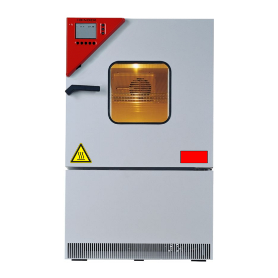
Page 10: Word Message Panel Structure
Hot surface (on outer unit door) Service label Figure 1: Position of labels on the unit Keep safety labels complete and legible. Replace safety labels that are no longer legible. Contact BINDER service for these replacements. MK (E2.1) 10/2014 page 10/73... -
Page 11: Type Plate
E2.1 Internet: www.binder-world.com Made in Germany Figure 2: Type plate (example of MK 53 regular unit) Indications of the type plate (example) Information BINDER Manufacturer: BINDER GmbH MK 53 Model designation Alternating climate chamber Device name Serial No. 00-00000 Serial no. of the unit... -
Page 12: General Safety Instructions On Installing And Operating The Alternating Climate Chamber Mk
1/119 laboratory guidelines issued by the employers’ liability insurance association) (for Germany). BINDER GmbH is only responsible for the safety features of the unit provided skilled electricians or quali- fied personnel authorized by BINDER perform all maintenance and repair, and if components relating to chamber safety are replaced in the event of failure with original spare parts. - Page 13 Any solvent contained in the charging material must not be explosive or inflammable. I.e., irrespective of the solvent concentration in the steam room, NO explosive mixture with air must form. The temperature inside the chamber must lie below the flash point or below the sublimation point of the charging material. Familiarize yourself with the physical and chemical properties of the charging material, as well as the con- tained moisture constituent and its behavior with the addition of heat energy.
-
Page 14: Intended Use
The charging material shall not contain any corrosive ingredients that may damage the ma- chine components made of stainless steel, aluminum, and copper. Such ingredients include in particular acids and halides. Any corrosive damage caused by such ingredients is excluded from liability by BINDER GmbH. MK (E2.1) 10/2014 page 14/73... -
Page 15: Unit Description
Unit description The alternating climate chamber MK is a specially developed precision refrigerating / warming cabinet with an unrivalled capacity, which by far exceeds the capabilities of normal test cabinets. With its extensive program control, the alternating climate chamber MK is designed for optimum performance with regard to temperature accuracy and rapid heating up and cooling down phases, thus providing the ideal facilities for solving all the problems which occur during material as well as ageing and stress tests. -
Page 16: Unit Overview
Unit overview Figure 3: Alternating climate chamber MK 53 Instrument box Door handle Inspection window Unit door Refrigerating machine Instrument box MK Figure 4: Triangle instrument box MK Microprocessor program controller MB1 Main power switch ON/OFF MK (E2.1) 10/2014 page 16/73... -
Page 17: Lateral Control Panel Mk
Lateral control panel MK RESET CL. 2.0 (6a) (6b) Figure 5: Lateral control panel at the left side of the refrigerating machine with options over-/under temperature safety device, and analog output (3) Free place for optional button (4) Switch for interior chamber light on / off (5) RESET button for option over-/under temperature safety device class 2 (option, chap. -
Page 18: Completeness Of Delivery, Transportation, Storage, And Installation
Second-hand units are units that were used for a short time for tests or exhibitions. They are thoroughly tested before resale. BINDER ensures that the chamber is technically sound and will work flawlessly. Second-hand units are marked with a sticker on the unit door. Please remove the sticker before commis- sioning the unit. -
Page 19: Guidelines For Safe Lifting And Transportation
• Permissible ambient temperature range during transport: -10 °C / 14 °F to +60 °C / 140 °F. You can order transport packing and pallets for moving or shipping purposes from BINDER service. Storage Intermediate storage of the unit is possible in a closed and dry room. Observe the guidelines for tempo- rary decommissioning (chap. - Page 20 Permissible ambient temperature range during operation: +18 °C / 64.4 °F to +32 °C / 89.6 °F. At elevated ambient temperature values, fluctuations in temperature can occur. The ambient temperature should not be substantially higher than the indicated ambient tem- perature of +25 °C / 77 °F to which the specified technical data relate.
-
Page 21: Installation And Connections
Installation and connections Electrical connection The alternating climate chamber MK is supplied ready for connection. • Shockproof plug, power supply voltage 230 V (1N~) +/- 10 %, 50 Hz Fixed power connection cable 1800 mm / 5.9 ft in length •... -
Page 22: Start Up
Start up After connecting the electrical supply (chap. 4), turn on the unit by the main power switch (2). Warming chambers may release odors in the first few days after commissioning. This is not a quality de- fect. To reduce odors quickly we recommend heating up the chamber to its nominal temperature for one day and in a well-ventilated location. -
Page 23: Operating Modes
500. Programming can be done directly through the keypad of the controller or graphically through the software APT-COM™ 3 DataControlSystem (option, chap. 14.1) specially developed by BINDER. Behavior after power failure After the power returns, the unit continues to function in the original operating mode it was in previously before an actual power failure had occurred. - Page 24 Structure of toggling between Idle Mode / Manual Mode / Program Mode: Idle Mode HAND EXIT Menu Program start Manual Mode (HAND) Program Mode (AUTO) EXIT For control reasons the refrigeration machine starts with a delay time of about 30 seconds. The refrigeration machine also turns off with a 90 seconds delay.
-
Page 25: Controller Mb1 Settings
Controller MB1 settings Selection of the menu language The display program controller MB1 controls the temperature inside the alternating climate chamber. The controller communicates by a menu guide using real words in German, English and French. The selection of the desired menu language is located in the sub-menu “User-Level” of the “User- Settings“... -
Page 26: Overview Of Program Controller Mb1 Displays
VIEW -> CONFIG VIEW-> VIEW-> The NORMAL DISPLAY enables comparison of the Contact BINDER service easily. current temperature (W) to the set-point value (X) or shows the fan working rate. NORMAL DISPLAY Idle Mode 08:43:55 15.12.13 08:43:55 15.12.13 26.8... -
Page 27: Menu Settings In The "User-Settings" Menu
Menu settings in the “User-settings” menu User-settings Instrument data Contrast Displ. Power down Contin. operation User Level Safety control. Set. + 105.0 °C Safety control. Act + 100.8 °C Instrument data • Instrument Name Enter an individual name of the alternating climate chamber. •... -
Page 28: Menu Settings In The "User Level" Menu
Menu settings in the “User Level” menu User Level Date and time Summer time Language English Temperature unit °C Active Buzzer Safety controller User-code No. Date and time Enter the actual date and time to provide the proper measurement records. Data is displayed in the chart recorder function (chap. -
Page 29: Graphical Representation Of The Historical Measurement (Chart Recorder Function)
Graphical representation of the historical measurement (chart recorder function) The representation of data imitates a chart recorder and allows recalling any set of measured data of any point of time taken from the recorded period. Normal display of the chart recorder function: Top left: The actual date and time are displayed. - Page 30 You can also directly enter any cursor position as a numerical input. History representation: Toggling to any defined moment: 11:34:27 15.12.13 Press button . The window “Cursor position” opens to enter date and time. Cursor position Date 15.12.13 Time 11:34:27 Select date or time with the arrow buttons and confirm with ENTER.
-
Page 31: Setting The Storage Rate
Setting the storage rate 11:44:17 20.12.13 User-Settings Configuration 2 Configuration 1 CONFIG Parameters Choose variation 11:44:17 20.12.13 User-Settings Configuration 2 Configuration 1 Parameters Choose variation User-Code ? Grenzwert +00001 Offset Configuration 1 Diagram view Feed view Time/div Event tracks Datalogging Interface Analog view Datalogging... -
Page 32: Manual Mode
Manual Mode In Manual Mode (HAND) you can enter a temperature set-point, the fan speed (0% to 100%), and the switching-state of up to 8 operation lines. Operation line 1 is used to control the bedew protection (chap. 10). The other operation lines are non-functional. All settings remain valid for Manual Mode (HAND) until the next manual change, if the unit had been turned off or in case of toggling to Idle Mode or Program Mode (AUTO). -
Page 33: Performance After Power Failure In Manual Mode
8 operation lines. Operating line 1 serves to control the bedew protection (chap. 10). The other operation lines are non-functional. Programming is possible directly by the keypad of the controller or graphically by the software APT- COM™ 3 DataControlSystem (option, chap. 14.1) specially developed by BINDER. MK (E2.1) 10/2014 page 33/73... -
Page 34: Overview Menu-Based Program Entry
Overview menu-based program entry Display showing the initial normal display in Idle Mode 08:43:55 15.12.13 26.8 TEMP °C CONFIG HAND VIEW-> Press the “PGM” button. The window program selection appears 08:43:55 15.12.13 Prog select Fr. Abs. 372 Prog 1 PROG 01 ... - Page 35 You can enter Program sections into this program table. Press the “PGM” button. An inquiry display appears allowing you to enter or delete individual program sections: ZP-Abschnitt Abs. Nr. 5 insert delete In this view, new program lines can be entered or deleted: New lines are added below in the table New lines are added above a previously selected line insert...
-
Page 36: Selecting Between Set-Point Ramp And Set-Point Step
Performance after completing the program: The controller changes to Idle Mode. The heating and the cooling are inactive; the chamber approximates ambient temperature. The fan is off. Selecting between set-point ramp and set-point step Temperature set-points always refer to the start of a program section, i.e., at the beginning of each pro- gram section the entered temperature set-point is targeted. - Page 37 Program entry as set-point ramp (example) W/°C Maximum tolerance Minimum tolerance t/min. Operation line 1 = Bedew protection t/min. Program table corresponding to the diagram above: Program Set-point Section Operation Target No. of Min. Max. section temp. time line1 section cycles tolerance tolerance...
- Page 38 Program entry as set-point step (example) W/°C Maximum tolerance Minimum tolerance t/min. Operation line 1 = Bedew protection t/min. Program table corresponding to the diagram above: Program Set-point Section Operation Target No. of Min. Max. section temp. time line1 section cycles tolerance tolerance...
-
Page 39: Information On Programming Different Temperature Transitions
The controller MB1 displays more menu entries than those described in this manual. These are password protected because they are relevant for service purpose only and the user must not modify them. Only service authorized by BINDER can access these entries. MK (E2.1) 10/2014... -
Page 40: Repetition Of A Section Or Several Sections Within A Program
Repetition of a section or several sections within a program Here we use the example of a set-point ramp temperature program of chap. 9.3. The shaded sections 02 and 03 shall be repeated e.g. 30 times. Program Set-point Section Operation Target No. -
Page 41: Starting A Previously Entered Program
Starting a previously entered program The program has to be previously entered via a programming table (chap. 9.3, 9.5). 09:11:55 15.12.13 Idle mode 26.8 No heating or cooling function. TEMP °C The fan is off (factory setting) CONFIG VIEW-> HAND 09:12:02 15.12.13 Select a program place Program start... -
Page 42: Temperature Profile And Operation Lines Template
Temperature profile and operation lines template Programmer : Program No. (1 to 25): Date: Program title: Operation line 1 controls the bedew protection Project: On = active Off = not active °C Bedew protection time MK (E2.1) 10/2014 page 42/73... -
Page 43: Program Table Template
9.10 Program table template Programmer : Program No. (1 to 25): Date: Program title: Operation line 1 Controls the bedew protection Off = not active Project: On = active Section Set-point Fan speed [%] Section time Operation line 1 Start section for Number of repeat Tolerance- Tolerance-... -
Page 44: Bedew Protection Facility (Operation Line 1)
Bedew protection facility (operation line 1) The bedew protection condensates the chamber humidity at the coldest point in order to avoid the sam- ples becoming wet from condensation. Bedew protection is performed by the evaporator and can be pro- grammed On/Off via operation line 1 in Manual Mode (HAND) and in Program Mode (AUTO). The other operation lines are non-functional. -
Page 45: Temperature Safety Devices
The user cannot restart the device again. This protective cut-off device is located internally. Only a service specialist can replace it. Therefore, please contact an author- ized service provider or BINDER service. 11.2 Safety controller (over-temperature safety device class 2) The alternating climate chamber MK is equipped with an over temperature safety device class 2 acc. - Page 46 Checking and setting the safety controller set-point type and safety controller set-point: Unlock the keyboard locking (option, chap. 14.3). User-settings Instrument data Contrast Displ. Power down Contin. operation User Level Safety control. Set. + 105.0 °C Grundeinstellung Safety control. Act + 100,8 °C User level code no.
-
Page 47: Over/Under Temperature Safety Device Class 2 (Option)
11.3 Over/under temperature safety device class 2 (option) The over-/under temperature safety device (6) consists of two entry modules located in the lateral control panel. Both modules can be set from -50 °C / -58°F up to 200 °C / 392°F and serve to define the maximum high and low temperature limits. -
Page 48: Notification And Alarm Functions
2. Press the “RESET” button to reset the notification or alarm message. CAUTION In case the “RESET” button does not cancel the notification or alarm indication, the reason for the disturbance was not removed correctly Contact BINDER service. MK (E2.1) 10/2014 page 48/73... -
Page 49: Notes On Refrigerating Operation
Notes on refrigerating operation Defrosting: BINDER alternating climate chambers are very diffusion-proof. To ensure high temperature precision there is no automatic cyclic defrosting device. The refrigerating system largely avoids icing of the evapora- tion plates. However, at very low temperatures the moisture in the air can condense on the evaporator leading to icing. -
Page 50: Options
The alternating climate chamber MK is regularly equipped with a serial interface RS 422 that can connect the BINDER communication software APT-COM™ 3 DataControlSystem. The actual temperature values are given at adjustable intervals. Programming can be performed graphically via PC. Up to 30 chambers with RS 422 interface can be cross-linked. -
Page 51: Data Logger Kit
14.4 Data logger kit BINDER Data Logger Kits offer an independent long-term measuring system for temperature. They are equipped with a keyboard and a large LCD display, alarm functions and a real-time function. Measure- ment data are recorded in the Data Logger and can be read out after the measurement via the RS232 interface of the Data Logger. -
Page 52: Maintenance, Cleaning, And Service
With an increased amount of dust in the ambient air, clean the condenser fan (by suction or blowing) sev- eral times a year. We recommend taking out a maintenance agreement. Please consult BINDER Service. BINDER telephone hotline: +49 (0) 7462 2005 555... -
Page 53: Cleaning And Decontamination
Do NOT use a neutral cleaning agent on zinc coated surfaces. Do not use cleaning agents that may cause a hazard due to reaction with components of the device or the charging material. If there is doubt regarding the suitability of cleaning products, please contact BINDER service. -
Page 54: Decontamination
We recommend using disinfectant Art. No. 1002-0022. For chemical disinfection, we recommend using the disinfectant spray Art. No. 1002-0022. Any corrosive damage that may arise following use of other disinfectants is excluded from liability by BINDER GmbH. MK (E2.1) 10/2014 page 54/73... -
Page 55: Sending Back The Unit To The Binder Gmbh
15.3 Sending back the unit to the BINDER GmbH If you send a BINDER product to us for repair or any other reason, we will only accept the product upon presentation of an authorization number (RMA number) that has previously been issued to you. We will issue an authorization number after receiving your complaint either in writing or by telephone prior to your sending the BINDER product back to us. -
Page 56: Disposal
According to directive 2002/96/EC of the European Parliament and of the Council on waste electrical and electronic equipment (WEEE), BINDER devices are classified as “monitoring and control instruments” (category 9) only intended for professional use“. They must not be disposed of at public collecting points. - Page 57 (Elektro- und Elektronikgerätegesetz, ElektroG) from 23 March 2005, BGBl. I p. 762 or contact BINDER service who will organize taking back and disposal of the unit according to the German national law for electrical and electronic equipment (Elektro- und Elektronikgerätegesetz, ElektroG) from 23 March 2005, BGBl.
-
Page 58: Disposal Of The Unit In The Member States Of The Ec Except For The Federal Republic Of Germany
According to directive 2002/96/EC of the European Parliament and of the Council on waste electrical and electronic equipment (WEEE), BINDER devices are classified as “monitoring and control instruments” (category 9) only intended for professional use“. They must not be disposed of at public collecting points. -
Page 59: Disposal Of The Unit In Non-Member States Of The Ec
Alteration of the environment. For final decommissioning and disposal of the alternating climate chamber, please con- tact BINDER service. Observe the statutory regulations for appropriate, environmentally friendly disposal. The main board of the alternating climate chamber includes a lithium cell. Please dispose of it according to national regulations. -
Page 60: Troubleshooting
Troubleshooting Fault description Possible fault cause Required measures Heating Controller defective. Pt 100 sensor defective. Contact BINDER service. Chamber heating permanently, set-point not held. Semiconductor relay defective. Controller not adjusted. Calibrate and adjust controller. Heating element defective. Chamber doesn’t heat up. - Page 61 Set the fan speed to the desired Fan does not turn Fan speed set to 0%.. value. Repair must only be performed by qualified service personnel authorized by BINDER. Repaired units must comply with the BINDER quality standards. MK (E2.1) 10/2014 page 61/73...
-
Page 62: Technical Description
December 1996 by TÜV CERT). All test equipment used is subject to the administration of meas- urement and test equipment that is also constituent part of the BINDER QM DIN EN ISO 9001 systems. They are controlled and calibrated to a DKD standard at regular intervals. -
Page 63: Technical Data Mk 53 (E2.1)
+25 °C / 77 °F and a power supply voltage fluctuation of ±10. The temperature data is determined in ac- cordance to BINDER factory standard following DIN 12880, observing the recommended wall clearances of 10 % of the height, width and depth of the inner chamber. Technical data refers to 100% fan speed. -
Page 64: Equipment And Options Mk 53
18.5 Equipment and options MK 53 To operate the alternating climate chamber MK, use only original BINDER accessories or ac- cessories / components from third-party suppliers authorized by BINDER. The user is respon- sible for any risk arising from using unauthorized accessories. -
Page 65: Accessories And Spare Parts Mk 53
18.6 Accessories and spare parts MK 53 BINDER GmbH is responsible for the safety features of the unit only, provided skilled electri- cians or qualified personnel authorized by BINDER perform all maintenance and repair, and if components relating to chamber safety are replaced in the event of failure with original spare parts. -
Page 66: Heating-Up And Cooling-Down Graphs
18.7 Heating-up and cooling-down graphs The maximal speed of temperature change is 4.1 K/min in refrigerating operation and 4.6 K/Min in heating operation. Heating-up times MK 53: Cooling-down times MK 53: 18.8 Heat compensation Bringing in a heat load leads to continuous operation of refrigerating machine. In this case frequent maintenance intervals are necessary. -
Page 67: Dimensions Mk 53
18.9 Dimensions MK 53 MK (E2.1) 10/2014 page 67/73... -
Page 68: Contamination Clearance Certificate
Contamination clearance certificate Unbedenklichkeitsbescheinigung 19.1 For units located outside North America and Central America Declaration with regard to safety and health Erklärung zur Sicherheit and gesundheitlichen Unbedenklichkeit The German Ordinance on Hazardous Substances (GefStofV), and the regulations regarding safety at the workplace, require that this form be filled out for all products that are returned to us, so that the safety and health of our employees can be warranted. - Page 69 Kind of transport / transporter / Transportweg/Spediteur: Transport by (means and name of transport company, etc.) Versendung durch (Name Spediteur o.ä.) __________________________________________________________________________________ Date of dispatch to BINDER GmbH / Tag der Absendung an BINDER GmbH ___________________________________________________________________________________ MK (E2.1) 10/2014 page 69/73...
- Page 70 We are aware that, in accordance with Article 823 of the German Civil Code (BGB), we are directly liable with regard to third parties, in this instance especially the employees of BINDER GmbH, who have been entrusted with the handling / repair of the unit / component. / Es ist uns bekannt, dass wir gegenüber Dritten –...
-
Page 71: For Units In North America And Central America
After we have received and reviewed the complete information we will decide on the issue of a RMA num- ber. Please be aware that size specifications, voltage specifications as well as performance specifications are available on the internet at www.binder-world.us at any time. Take notice of shipping laws and regulations. - Page 72 Customer (End User) Decontamination Declaration Health and Hazard Safety declaration To protect the health of our employees and the safety at the workplace, we require that this form is com- pleted by the user for all products and parts that are returned to us. (Distributors or Service Organizations cannot sign this form) NO RMA number will be issued without a completed form.
- Page 73 4.5 Shipping laws and regulations have not been violated. I hereby commit and guarantee that we will indemnify BINDER Inc. for all damages that are a con- sequence of incomplete or incorrect information provided by us, and that we will indemnify and hold harmless BINDER Inc.
Need help?
Do you have a question about the APT.line MK E2.1 Series and is the answer not in the manual?
Questions and answers