Table of Contents
Advertisement
Quick Links
Operating Manual
APT.line™ MK
Temperature test chambers for natural simulation
with display program controller MB1
BINDER GmbH
Address
Tel.
Fax
Internet
E-mail
Service Hotline
Service Fax
Service E-Mail
Service Hotline USA
Service Hotline Spain
Service Hotline Asia Pacific
Service Hotline Russia and CIS +7 495 98815 17
Issue 03/2007
Post office box 102
D-78502 Tuttlingen
+49 7462 2005 0
+49 7462 2005 100
http://www.binder-world.com
info@binder-world.com
+49 7462 2005 555
+49 7462 2005 93 555
service@binder-world.com
+1 866 885 9794 or +1 631 224 4340
+34 9492 677 23
+852 39070500 or +852 39070503
Art. Nr. 7001-0028
Advertisement
Table of Contents

Related Manuals for Binder APT.line MK Series


Summary of Contents for Binder APT.line MK Series
- Page 1 Operating Manual APT.line™ MK Temperature test chambers for natural simulation with display program controller MB1 BINDER GmbH Address Post office box 102 D-78502 Tuttlingen Tel. +49 7462 2005 0 +49 7462 2005 100 Internet http://www.binder-world.com E-mail info@binder-world.com Service Hotline +49 7462 2005 555...
- Page 2 EG - KONFORMITÄTSERKLÄRUNG EC - DECLARATION OF CONFORMITY CE - DECLARATION DE CONFORMITE Anbieter / Supplier / Fournisseur: BINDER GmbH Im Mittleren Ösch 5, D-78532 Tuttlingen Anschrift / Address / Adresse: Temperaturprüfschränke für natürliche Simulation mit Programmre- Produkt / Product / Produit:...
- Page 3 Die oben beschriebenen Produkte tragen entsprechend die Kennzeichnung CE. The products described above, corresponding to this, bear the CE-mark Les produits décrits ci-dessus, en correspondance, portent l’indication CE. D-78532 Tuttlingen, 10.08.2006 BINDER GmbH P. M. Binder Dr.-Ing. V. Kek Geschäftsführender Gesellschafter Leiter F & E Managing Director Head of R &...
-
Page 4: Table Of Contents
CONTENTS SAFETY........................6 Legal considerations ...........................6 Structure of the safety instructions......................6 Localization / position of safety labels at the unit................8 Type plate ............................9 General safety instructions on installing and operating the temperature test chamber for natural simulation MK........................10 Intended use .............................12 UNIT DESCRIPTION .................... - Page 5 Pt 100 (option)........................45 14. MAINTENANCE, CLEANING, AND SERVICE ............ 45 14.1 Maintenance intervals, service......................45 14.2 Cleaning and decontamination ......................46 14.3 Sending back the unit to the BINDER GmbH ...................47 15. DISPOSAL......................48 15.1 Disposal of the transport packing .....................48 15.2 Decommissioning..........................48 15.3 Disposal of the unit in the Federal Republic of Germany ..............48...
-
Page 6: Safety
All obligations on the part of BINDER derive from the respective purchase contract, which also contains the entire and ex- clusively valid statement of warranty administration. The statements in this manual neither augment nor restrict the contractual warranty provisions. - Page 7 CAUTION Indicates a potentially hazardous situation which, if not avoided, may result in moderate or minor (re- versible) injury CAUTION Indicates a potentially hazardous situation which, if not avoided, may result in damage to the product and/or its functions or of a property in its proximity. Safety alert symbol Use of the safety alert symbol indicates risk of injury.
-
Page 8: Localization / Position Of Safety Labels At The Unit
The following labels are located on the unit: Pictograms (Warning signs) Service label Hot surface Figure 1: Position of labels on the unit Keep safety labels complete and legible. Replace safety labels that are no longer legible. Contact BINDER service. MK 03/2007 page 8/64... -
Page 9: Type Plate
5405194 / 5601143 / 5773287 / 6079403 D 78532 Tuttlingen / Germany MK 720 Serial No. 00-00000 Tel. + 49 (0) 7462/ 2005-0 Made in Germany Internet: www.binder-world.com Figure 3: Type plate (example of MK 720 regular unit) Indications of the type plate Information Nominal temperature 180°C... -
Page 10: General Safety Instructions On Installing And Operating The Temperature Test Chamber For Natural Simulation Mk
(formerly ZH 1/119 laboratory guidelines issued by the employers’ liability insurance association) (for Germany). BINDER GmbH is only responsible for the safety features of the unit provided skilled electricians or quali- fied personnel authorized by BINDER perform all maintenance and repair, and if components relating to chamber safety are replaced in the event of failure with original spare parts. - Page 11 The temperature test chamber MK does not possess any measures for explosion protection. DANGER Explosion hazard. Danger of death. ∅ Do NOT introduce any substance combustible or explosive at working temperature into the temperature test chamber. ∅ NO explosive dust or air-solvent mixture in the inner chamber. Any solvent contained in the charging material must not be explosive or inflammable.
-
Page 12: Intended Use
Intended use Temperature test chambers MK for natural simulation are suitable for temperature treatment of solid or pulverized charging material, as well as bulk material, using the supply of heat or cold. They are suitable for harmless materials. A mixture of any component of the charging material with air must NOT be explo- sive. -
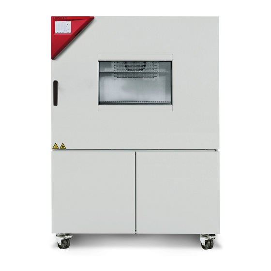
Page 13: Unit Overview
Unit overview Figure 4: Temperature test chamber for natural simulation MK 53 Instrument box Door handle Inspection window Outer door Refrigerating machine Instrument box MK Figure 5: Triangle box MK Microprocessor program controller MB1 Main switch ON/OFF MK 03/2007 page 13/64... -
Page 14: Lateral Control Panel Mk
Lateral control panel MK RESET CL. 2.0 (6a) (6b) Figure 6: Lateral control panel at the left side of the refrigerating machine with options over-/under temperature safety device, and analog output (3) Free place for optional button (4) Switch for interior chamber light on / off (5) RESET button for option over-/under temperature safety device class 2 (option, chap. -
Page 15: Scope Of Delivery, Transportation, Storage, And Installation
Second-hand units are units that have been used for a short time for tests or exhibitions. They are thor- oughly tested before resale. BINDER guarantees the technically flawless state of the chamber. Second-hand units are marked as such with a sticker on the unit door. Please remove the sticker before commissioning the unit. -
Page 16: Guidelines For Safe Lifting And Transportation
Without the pallet the unit is in imminent danger of overturning. • Permissible ambient temperature range during transport: -10°C to +60°C. You can order transport packing and pallets for transportation purposes from BINDER service. Storage Intermediate storage of the unit is possible in a closed and dry room. -
Page 17: Installation And Connections
The ambient temperature should not be substantially higher than the indicated ambient tem- perature of +20°C to which the specified technical data relate. For other ambient conditions, deviations from the indicated data are possible. • Permissible ambient humidity: 70 % r.H. max., non-condensing. •... -
Page 18: Start Up
Start up • After connecting the electrical supply (chap. 4), switch on the unit by the main switch (2). Function overview of screen program controller MB1 Pilot lamp: Ready for operation 08:43:55 20.12.05 EXIT button (to exit a menu point) EXIT 36.8 25.0... -
Page 19: Behavior After Power Failure
500. Programming can be done directly through the keypad of the controller or graphically through the soft- ware APT-COM™ 3 DataControlSystem (option, chap. 13.1) specially developed by BINDER. Behavior after power failure After power return, the unit continues operating in the operating mode actual before power failure. -
Page 20: Settings Of The Controller Mb1
Settings of the controller MB1 Selection of the menu language The screen program controller MB1 controls the temperature inside the temperature test chamber. The controller communicates by a plain language menu guide in German, English and French. The selection of the desired menu language is located in the sub-menu “User-Level” of the menu “User- Settings“. -
Page 21: Function Overview Program Controller Mb1
CONFIG VIEW-> VIEW-> The NORMAL DISPLAY enables comparison of the current temperature (W) to the set-point value (X) or Contact BINDER service easily. shows the fan working rate. NORMAL DISPLAY Idle Mode 08:43:55 15.12.05 08:43:55 15.12.05 26.8 TEMP °C... -
Page 22: Settings In The Menu "User-Settings
Settings in the menu “User-settings” User-settings Instrument data Contrast Displ. Power down Contin. operation User Level Safety control. Set. + 105.0 °C Safety control. Act + 100.8 °C Instrument data • Instrument Name Enter an individual name of the temperature test chamber. •... -
Page 23: Settings In The Menu "User Level
Settings in the menu “User Level” User Level Date and time Summer time Language English Temperature unit °C Active Buzzer Safety controller User-code No. Date and time Enter the actual date and time to provide the measurement records with the correct relation of time. Data are displayed in the chart recorder function (chap. -
Page 24: Graphical Representation Of The Measurement Course (Chart Recorder Function)
Graphical representation of the measurement course (chart recorder function) This way of data representation imitates a chart recorder and permits recalling any set of measured data of any point of time out of the recorded period. Normal display of the chart recorder function: Top left: The actual date and time are displayed. - Page 25 You can also directly enter any cursor position as a numerical input. History representation: Toggling to any instant: 11:34:27 15.12.05 Press button . The window “Cursor position” o- pens to enter date and time. Cursor Date 15.12.05 Time 11:34:27 Select date or time with the arrow buttons and confirm with ENTER.
-
Page 26: Setting The Storage Rate
Setting the storage rate 11:44:17 20.12.05 User-Settings Configuration 2 Configuration 1 CONFIG Parameters Choose variation 11:44:17 20.12.05 User-Settings Configuration 2 Configuration 1 Parameters Choose variation User-Code ? Grenzwert +00001 Offset Configuration 1 Diagram view Feed view Time/div Event tracks Datalogging Interface Analog view Datalogging... -
Page 27: Manual Mode
Manual Mode In Manual Mode (HAND) you can enter a temperature set-point, the fan speed (0% to 100%), and the switching-state of up to 8 operation lines. Operation line 1 is used to control the bedew protection (chap. . 10). The other operation lines are non-functional. All settings remain valid for Manual Mode (HAND) until the next manual change, also if the unit had been switched off or in case of toggling to Idle Mode or Pro- gram Mode (AUTO). -
Page 28: Behavior After Power Failure In Manual Mode
8 operation lines can be entered. Operating line 1 is used to control the bedew protection (chap. 10). The other operation lines are non-functional. Programming is possible directly by the keypad of the controller or graphically by the software APT- COM™ 3 DataControlSystem (option, chap. 13.1) specially developed by BINDER. MK 03/2007 page 28/64... -
Page 29: Overview Menu-Based Program Entry
Overview menu-based program entry Screen showing the initial normal display in Idle Mode 08:43:55 15.12.05 26.8 TEMP °C CONFIG HAND VIEW-> Hit button PGM. The window program selection appears 08:43:55 15.12.05 Prog select Fr. Abs. 372 Prog 1 PROG 01 Prog 2 PROG 02 Prog 3... - Page 30 Hit the PGMK button. An inquiry screen appears offering to enter or delete individual program sections: ZP-Abschnitt Abs. Nr. 5 insert delete In this view, new program lines can be entered or deleted: New lines are added below in the table insert New lines are added above a previously selected line delete...
-
Page 31: Selecting Between Set-Point Ramp And Set-Point Step
Behavior after completing the program: The controller changes to Idle Mode. The heating is inactive; the chamber approximates ambient tem- perature. The fan is off. Selecting between set-point ramp and set-point step Temperature set-points always refer to the start of a program section, i.e., at the beginning of each pro- gram section the entered temperature set-point is targeted. - Page 32 Program entry as set-point ramp (example) W/°C Maximum tolerance Minimum tolerance t/min. Operation line 1 = Bedew protection t/min. Program table corresponding to the diagram above: Program Set-point Section Operation Target No. of Min. Max. section temp. time line1 section cycles tolerance tolerance...
- Page 33 Program entry as set-point step (example) W/°C Maximum tolerance Minimum tolerance t/min. Operation line 1 = Bedew protection t/min. Program table corresponding to the diagram above: Program Set-point Section Operation Target No. of Min. Max. section temp. time line1 section cycles tolerance tolerance...
-
Page 34: Advice For The Programming Of The Different Temperature Transitions
The controller MB1 displays more menu entries than those described in this manual. These are password protected because they are relevant for service purpose only and the user must not modify them. Only service authorized by BINDER shall access those entries. MK 03/2007... -
Page 35: Repetition Of A Section Or Several Sections Within A Program
Repetition of a section or several sections within a program The example of a set-point ramp temperature program of chap. 9.3 will serve as an example. The shaded sections 02 and 03 shall be repeated e.g. 30 times. Program Set-point Section Operation Target... -
Page 36: Starting A Previously Entered Program
Starting a previously entered program The program has to be previously entered via a programming table (chap. 9.3, 9.5). 09:11:55 15.12.05 Idle mode No heating function. 26.8 Fan is off TEMP °C (factory setting) CONFIG VIEW-> HAND 09:12:02 15.12.05 Select a program place P r o g r a m s t a r t Delayed program start P r o g r a m... -
Page 37: Temperature Profile Template
Temperature profile template Programmer : Program No. (1 to 25): Date: Program title: Operation line 1 controls the bedew protection Project: On = active Off = not active °C Bedew protection tim e MK 03/2007 page 37/64... -
Page 38: Program Table Template
9.10 Program table template Programmer : Program No. (1 to 25): Date: Program title: Operation line 1 Controls the bedew protection Project: On = active Off = not active Section Set-point Fan speed [%] Section time Operation line 1 Start section for Number of re- Tolerance- Tolerance-... -
Page 39: Bedew Protection Facility
Bedew protection facility The bedew protection condensates the chamber humidity at the coldest point in order to avoid the sam- ples becoming wet from condensation. Bedew protection is performed by the evaporator and can be pro- grammed On/Off via operation line 1 in Manual Mode (HAND) and in Program Mode (AUTO). The other operation lines are non-functional. -
Page 40: Temperature Safety Devices
The user cannot take the device into operation again. This protective cut-off device is located internally. Only a service specialist can replace it. In this case, please contact an authorized service or BINDER service. 11.2 Safety controller (over-temperature safety device class 2) The temperature test chamber for natural simulation MK is equipped with an over temperature safety device class 2 acc. - Page 41 Checking and setting safety controller set-point type and safety controller set-point: Unlock the keyboard locking (option, chap. 13.3). User-settings Instrument data Contrast Displ. Power down Contin. operation User Level Safety control. Set. + 105.0 °C Grundeinstellung Safety control. Act + 100,8 °C User level code no.
-
Page 42: Over/Under Temperature Safety Device Class 2 (Option)
11.3 Over/under temperature safety device class 2 (option) The over-/under temperature safety device (6) consists of two entry modules located in the lateral control panel. Both modules can be set from -50°C up to 200°C and serve to define the maximum high and low temperature limits. -
Page 43: Notifying And Alarm Functions
2. Press the RESET button to reset the note or the alarm message. CAUTION In case the RESET button does not cancel the notifying or alarm indication, the nature of disturbance has not been removed correctly. The operation of the unit remains interrupted. Contact BINDER service. MK 03/2007 page 43/64... -
Page 44: Options
Options 13.1 Communication software APT-COM™ 3 DataControlSystem (option) The temperature test chamber is regularly equipped with a serial interface RS 422 to which the BINDER communication software APT-COM™ 3 DataControlSystem can be connected. In adjustable intervals, the actual temperature value is put out. Programming can be performed graphically via PC. Up to 30 chambers with RS 422 interface can be cross-linked. -
Page 45: Additional Measuring Channel For Digital Object Temperature Indicator With Flexible Temperature Sensor Pt 100 (Option)
The object temperature data are put out together with the data of the temperature controller to the RS 422 interface as second measuring channel and can be documented by the communication software APT-COM™ (option, chap. 13.1) developed by BINDER. Technical data of the Pt 100 sensor: •... -
Page 46: Cleaning And Decontamination
We recommend taking out a maintenance agreement. Please consult BINDER Service. BINDER telephone hotline: +49 (0) 7462 2005 555 BINDER fax hotline: +49 (0) 7462 2005 93555 BINDER e-mail hotline: service@binder-world.com BINDER service hotline USA: +1 866 885 9794 or +1 631 224 4340 (toll-free in the USA) -
Page 47: Sending Back The Unit To The Binder Gmbh
14.3 Sending back the unit to the BINDER GmbH If you send a BINDER product to us for repair or any other reason, we will only accept the product upon presentation of an authorization number that has previously been issued to you. We will issue an authori- zation number after receiving your complaint either in writing or by telephone prior to your sending the BINDER product back to us. -
Page 48: Disposal
According to directive 2002/96/EC of the European Parliament and of the Council on waste electrical and electronic equipment (WEEE), BINDER devices are classified as “monitoring and control instruments” (category 9) only intended for professional use“. They must not be disposed of at public collecting points. - Page 49 (Elektro- und Elektronikgerätegesetz, ElektroG) from 23 March 2005, BGBl. I p. 762 or contact BINDER service who will organize taking back and disposal of the unit according to the German national law for electrical and electronic equipment (Elektro- und Elektronik- gerätegesetz, ElektroG) from 23 March 2005, BGBl.
-
Page 50: Disposal Of The Unit In The Member States Of The Ec Except For The Federal Republic Of Germany
According to directive 2002/96/EC of the European Parliament and of the Council on waste electrical and electronic equipment (WEEE), BINDER devices are classified as “monitoring and control instruments” (category 9) only intended for professional use“. They must not be disposed of at public collecting points. -
Page 51: Disposal Of The Unit In Non-Member States Of The Ec
Alteration of the environment. For final decommissioning and disposal of the temperature test chamber, please con- tact BINDER service. Observe the statutory regulations for appropriate, environmentally friendly disposal. The main board of the temperature test chamber includes a lithium cell. Please dispose of it according to national regulations. - Page 52 Fan does not turn Fan speed set to 0%.. Set the fan speed to the desired value. Repair must only be performed by qualified service personnel authorized by BINDER. Repaired units must comply with the BINDER quality standards. MK 03/2007 page 52/64...
-
Page 53: Technical Description
December 1996 by TÜV CERT). All test equipment used is subject to the administration of meas- urement and test equipment that is also constituent part of the BINDER QM DIN EN ISO 9001systems. They are controlled and calibrated to a DKD-Standard at regular intervals. -
Page 54: Technical Data Mk
17.4 Technical Data MK Unit size Exterior dimensions Width (including access port 80 mm with mm / inch 740 / 29.13 1160 / 45.67 1381 / 54.37 plug) Height (feet/rollers included) mm / inch 1242 / 48.90 1613 / 63.50 1997 / 78.62 Depth (including 55 mm controller and mm / inch... -
Page 55: Equipment And Options
17.5 Equipment and Options To operate the temperature test chamber, use only original BINDER accessories or accesso- ries from third-party suppliers authorized by BINDER. The user is responsible for any risk arising from using unauthorized accessories. Unit size... -
Page 56: Spare Parts
17.6 Spare parts BINDER GmbH is only responsible for the safety features of the unit provided skilled electri- cians or qualified personnel authorized by BINDER perform all maintenance and repair, and if components relating to chamber safety are replaced in the event of failure with original spare parts. -
Page 57: Heating-Up And Cooling-Down Graphs
17.7 Heating-up and cooling-down graphs The maximal speed of temperature change is 5 K/min in refrigerating operation and 5.2 K/Min in heating operation (MK 53, values measured according to IEC 60068-3-5). Heating-up times MK 90 100 Time / min. MK 53 MK 240 MK 720 Cooling-down times MK... -
Page 58: Heat Compensation
17.8 Heat compensation Heat compensation MK 53 1200 1000 Temperature Heat compensation MK 240 2000 1800 1600 1400 1200 1000 -41 -39 -36 -33 -30 -27 -25 -22 -20 -18 -16 -11 -4,8 -0,5 3,7 7,1 12,2 17 21,5 27,4 40,6 Temperature Bringing in a heat load leads to continuous operation of refrigerating machine. -
Page 59: Dimensions Mk 53
17.9 Dimensions MK 53 MK 03/2007 page 59/64... -
Page 60: Dimensions Mk 240
17.10 Dimensions MK 240 MK 03/2007 page 60/64... -
Page 61: Dimensions Mk 720
17.11 Dimensions MK 720 MK 03/2007 page 61/64... -
Page 62: Contamination Clearance Certificate
Contamination clearance certificate Unbedenklichkeitsbescheinigung Declaration of harmlessness with regard to safety and health Erklärung zur Sicherheit and gesundheitlichen Unbedenklichkeit The German Ordinance on Hazardous Substances (GefStofV), and the regulations regarding safety at the workplace, require that this form be filled out for all products that are returned to us, so that the safety and health of our employees can be warranted. - Page 63 Kind of transport / transporter / Transportweg/Spediteur: Transport by (means and name of transport company, etc.) Versendung durch (Name Spediteur o.ä.) __________________________________________________________________________________ Date of dispatch to BINDER GmbH / Tag der Absendung an BINDER GmbH ___________________________________________________________________________________ MK 03/2007 page 63/64...
- Page 64 We are aware that, in accordance with Article 823 of the German Civil Code (BGB), we are directly liable with regard to third parties, in this instance especially the employees of BINDER GmbH, who have been entrusted with the handling / repair of the unit / component. / Es ist uns bekannt, dass wir gegenüber Dritten –...
Need help?
Do you have a question about the APT.line MK Series and is the answer not in the manual?
Questions and answers