
Related Manuals for Harris M7300


Summary of Contents for Harris M7300
- Page 1 Installation and Product Safety Manual MM-014763-001 Rev. E, Sep/09 M7300 Mobile Radio VHF and 700/800 MHz Front and Remote-Mount Mobile Radios with CH-721 Scan and System Control Heads...
- Page 2 This manual is published by Harris Corporation without any warranty. Improvements and changes to this manual necessitated by typographical errors, inaccuracies of current information, or improvements to programs and/or equipment, may be made by Harris Corporation at any time and without notice.
-
Page 3: Table Of Contents
REGULATORY ..........................15 INTRODUCTION ............................16 GENERAL DESCRIPTION ....................... 16 3.1.1 VHF-Band M7300 Radio ..................... 16 3.1.2 Dual-Band 700 and 800 MHz M7300 Radio................ 16 3.1.3 General Information ......................16 RELATED PUBLICATIONS......................19 REPLACEMENT PARTS ........................20 TECHNICAL ASSISTANCE......................20 UNPACKING AND CHECKING THE EQUIPMENT ................ - Page 4 FRONT-MOUNT RADIO INSTALLATION..................64 REMOTE-MOUNT RADIO INSTALLATION .................64 10 MICROPHONE ATTACHMENT ......................65 11 OPTIONAL CABLES ..........................66 11.1 M5300/M7300 OPTION CABLE CA-012349-001 ................66 11.2 SERIAL PROGRAMMING CABLES CA-013671-010 AND -020 ...........69 11.3 CH-721 OPTION CABLE CA-011854-001..................70 11.4 CH-721 SERIAL PROGRAMMING CABLE CA-104861..............71 12 GPS NMEA-FORMATTED SERIAL DATA CONNECTION...............72...
- Page 5 Figure 5-1: Typical Front-Mount Mobile Radio Installation in a Standard Passenger Vehicle ......27 Figure 5-2: Typical Remote-Mount Mobile Radio Installation in a Standard Passenger Vehicle....... 27 Figure 5-3: M7300 Front-Mount and Remote-Mount Mobile Radios — Front and Rear Views......28 Figure 6-1: Recommended Antenna Mounting Locations with Antenna Part Numbers ........31 Figure 6-2: Crimping Instructions for TNC RF Connector .................
-
Page 6: Regulatory And Safety Information
Failure to comply with these precautions or with specific warnings elsewhere violates safety standards of design, manufacture, and intended use of the product. Harris Corporation assumes no liability for the customer's failure to comply with these standards. -
Page 7: Federal Communications Commission Regulations
1.2.1 Federal Communications Commission Regulations Before it was marketed in the United States, the M7300 two-way mobile radio was tested to ensure compliance with FCC RF energy exposure limits for two-way mobile radios. When two-way radios are used as a consequence of employment, the FCC requires users to be fully aware of and able to control their exposure to meet occupational requirements. -
Page 8: Mobile Antennas
MM-014763-001, Rev. E Based on the highest radiated RF power and the highest antenna gain in antennas to be used with M7300, the distances listed in Table 1-1 (for VHF radios) and Table 1-2 (for 700 and 800 MHz radios) are... -
Page 9: Occupational Safety Guidelines And Safety Training Information
MM-014763-001, Rev. E Table 1-2: Recommended Minimum Safe Lateral Distance from Transmitting Antenna Connected to a 700 & 800 MHz M7300 Mobile Radio RECOMMENDED MINIMUM LATERAL HUMAN BODY DISTANCE FROM TRANSMITTING ANTENNA ANTENNA PART NUMBER ANTENNA DESCRIPTION CONTROLLED UNCONTROLLED (Catalog Number) -
Page 10: Common Hazards
MM-014763-001, Rev. E Do not attempt any unauthorized modification to the radio. Changes or modifications to the radio may cause harmful interference and/or cause it to exceed FCC RF exposure limits. Only qualified personnel should service the radio. Always use only authorized accessories (antennas, control heads, speakers/mics, etc.). -
Page 11: Safe Driving Recommendations
Two-way radio systems must be operated in accordance with the rules and regulations of the local, regional, or national government. In the United States, the M7300 mobile radio must be operated in accordance with the rules and regulations of the Federal Communications Commission (FCC). Operators of two-way radio equipment, must be thoroughly familiar with the rules that apply to the particular type of radio operation. -
Page 12: Operating Tips
MM-014763-001, Rev. E Under U.S. law, operation of an unlicensed radio transmitter within the jurisdiction of the United States may be punishable by a fine of up to $10,000, imprisonment for up to two (2) years, or both. CAUTION OPERATING TIPS The following conditions tend to reduce the effective range of two-way radios and should be avoided whenever possible: ... -
Page 13: Specifications
MM-014763-001, Rev. E SPECIFICATIONS GENERAL 2.4 x 6.9 x 11.3 inches (6.1 x 17.5 x 28.7 centimeters) Dimensions, Front-Mount Mobile Radio: (Height x Width x Depth) (Includes knobs but not space required for mounting bracket and cables at rear of radio) 2.0 x 6.9 x 9.2 inches (5.1 x 17.5 x 23.4 centimeters) Dimensions, Remote-Mount Mobile Radio: (Height x Width x Depth) - Page 14 MM-014763-001, Rev. E Frequency Ranges of 700 & 800 MHz Radio: Receive: 700 MHz Operation: 764 to 767 MHz, 769 to 775 MHz and 773 to 776 MHz (repeater and talk-around operations) [See footnote 800 MHz Operation: 851 to 869 MHz (repeater and talk-around operations) Transmit: 700 MHz Talk-Around Operation: 764 to 767 MHz, 769 to 775 MHz and 773 to 776 MHz...
-
Page 15: Regulatory
MM-014763-001, Rev. E 15 watts RMS minimum into 4-ohm external speaker Speaker Audio Output Power: < 5% at 15 watts RMS into 4-ohm external speaker Speaker Audio Output Distortion: 1 watt minimum into 4-ohm headset Headset Audio Output Power: External Speaker Connection Local Control (Front-Mount Radio): 2-pin audio connector on rear of radio Remote Control (Trunk-Mount Radio):... -
Page 16: Introduction
GENERAL DESCRIPTION The M7300 mobile radio is a high-performance digital mobile radio. Shown in Figure 5-3 on page 28, the M7300 mobile radio is available in both a VHF-band-only radio and a dual-band 700 and 800 MHz radio. - Page 17 Front-mount and remote-mount configurations are available. In the front-mount configuration, the control head is an integral part of the mobile radio. In the remote-mount configuration of the M7300, the control head is located near the radio operator’s position and the radio is mounted remotely from the control head, typically in the vehicle’s trunk.
- Page 18 Digital Voice Systems, Inc. When operating on an OpenSky radio network, AMBE gives an M7300 the ability to provide exceptional voice quality via the limited bandwidth of the radio frequency path, even when the received RF signal is weak (i.e., even in “fringe” areas). AMBE is...
-
Page 19: Related Publications
MM-014763-001, Rev. E RELATED PUBLICATIONS The following publications contain additional information about the M7300 mobile radio: MM-014368-001 Quick Guide for OpenSky mode: Quick Guide for EDACS, Conventional MM-014369-001 and P25 (ECP) modes: MM-014716-001 Operator’s Manual (for all modes): ... -
Page 20: Replacement Parts
Customer Resource Center, call, fax or e-mail our ordering system: United States and Canada: Phone Number: 1-800-368-3277 (toll free) Fax Number: 1-800-833-7592 (toll free) PSPC _ CustomerFocus @ harris.com E-mail: International: Phone Number: 1-434-455-6403 ... -
Page 21: Unpacking And Checking The Equipment
A typical set of materials for an M7300 mobile radio installation includes: M7300 Mobile Radio — See Table 4-1 below for catalog and part numbers. CH-721 Scan or System Control Head — See Table 4-2 below for catalog and part numbers. -
Page 22: Table 4-3: Installation Kit Mamw-Nzn6W For Front-Mount M7300 Mobile Radio
Speaker, External Mobile; 20-Watt (with 4.6-foot cable). CA-012349-001 Cable, M5300/M7300 Option. See Section 11.1 (page 66). FM-104859-001 Cap, Waterproof (For CH-721’s DB-9 serial port connector). Table 4-4: Installation Kit MAMW-NZN7R for Remote-Mount M7300 Mobile Radio with CH-721 Control Head ITEM QTY. PART NUMBER DESCRIPTION KT23117 Kit, Remote-Mount Mobile Radio Mounting Bracket. -
Page 23: Table 4-5: Additional Options And Accessories For M7300 Mobile Radios
MM-014763-001, Rev. E Table 4-5: Additional Options and Accessories for M7300 Mobile Radios PART NUMBER DESCRIPTION AN102800V1 Antenna, 136 – 941 MHz Standard Rooftop-Mount; ¼-Wave*, 0 dBd Gain, with Mounting Base, 17-foot (5.2-meter) RG-58 A/U (or equivalent) Low- Loss RF Cable and Male TNC RF Connector; Field-Tuned*. -
Page 24: Material Inspection
If any are noted, contact the Customer Resource Center (see page 20) immediately to discuss and arrange the return of the equipment to Harris for replacement. Any unauthorized attempts to repair or modify CAUTION this equipment will void the warranty and could create a safety hazard. -
Page 25: Table 4-6: Additional Options And Accessories For Ch-721 Control Heads
MM-014763-001, Rev. E Mounting of the radio, control head, and/or antenna in ways other than those described in this manual may adversely affect performance, violate FCC rules on RF exposure, and even damage the unit, posing a potential safety hazard. CAUTION Table 4-6: Additional Options and Accessories for CH-721 Control Heads PART NUMBER... -
Page 26: Planning The Installation
MM-014763-001, Rev. E PLANNING THE INSTALLATION GENERAL INFORMATION Figure 5-1 on page 27 illustrates a typical front-mount radio installation, and Figure 5-2 on page 27 illustrates a typical remote-mount radio installation. Before starting, plan the installation carefully so it will meet the following requirements: ... -
Page 27: Figure 5-1: Typical Front-Mount Mobile Radio Installation In A Standard Passenger Vehicle
MM-014763-001, Rev. E MOBILE ANTENNA GPS ANTENNA M7300 FRONT-MOUNT MOBILE RADIO VEHICLE BATTERY IN-LINE WATERPROOF FUSE HOLDER & AGC FUSE (20-AMP FOR RADIO) GROMMET (MOUNTED IN FIREWALL) VEHICLE SPEAKER FUSE BOX MOBILE ANTENNA CABLE GPS ANTENNA CABLE Figure 5-1: Typical Front-Mount Mobile Radio Installation in a Standard Passenger Vehicle... -
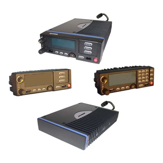
Page 28: Figure 5-3: M7300 Front-Mount And Remote-Mount Mobile Radios - Front And Rear Views
(Enlarged) 44-Pin I/O Connector Antenna 9-Pin Serial Port Connector Connector (female TNC) CAN Port Connectors (2 places) GPS Antenna Port (optional) DC Power Cable (with 3-Pin Connector) Figure 5-3: M7300 Front-Mount and Remote-Mount Mobile Radios — Front and Rear Views... -
Page 29: Locating Components
MM-014763-001, Rev. E LOCATING COMPONENTS Plan the mounting locations of all components (radio, control head, antenna, and cables) and determine the routes for all wiring and cables. Particularly consider the connection of the radio for planning purposes. Determine the customer’s preferences, if any, for location of components. Comply with these preferences as long as they are consistent with safety recommendations and guidelines presented in this manual, and other generally accepted professional radio installation practices. -
Page 30: Antenna Installation
MM-014763-001, Rev. E ANTENNA INSTALLATION ANTENNA MOUNTING LOCATIONS At this time, review all information presented in the REGULATORY AND SAFETY INFORMATION section of this manual (see page 6). A transmitting antenna must be installed in accordance with the guidelines presented in the REGULATORY AND SAFETY INFORMATION section. -
Page 31: Figure 6-1: Recommended Antenna Mounting Locations With Antenna Part Numbers
MM-014763-001, Rev. E TOP VIEW OF A TYPICAL VEHICLE LOCATION(S) ANTENNA ANTENNA DESCRIPTION PART NO.* AN102800V1 136 to 941 MHz Standard Rooftop-Mount, ¼-Wave, 0 dBd Gain AN102800V2 136 to 941 MHz Thick Rooftop-Mount, ¼-Wave, 0 dBd Gain ... -
Page 32: Install The Gps Antenna (Required Only If Radio Has Gps Receiver Option)
(Required Only if Radio has GPS Receiver Option) If the M7300 radio is equipped with the GPS receiver option, the GPS receiver requires connection to an externally-mounted GPS antenna. The GPS antenna must be kept at least six (6) inches away from any other antenna mounted on the vehicle and it must have at least six inches of surface ground plane beneath it. - Page 33 MM-014763-001, Rev. E A combination (“combo”) antenna kit includes a GPS antenna built into the base of the mobile antenna. Refer to Table 4-5 (page 23) and/or Figure 6-1 (page 31) for available combo antennas. 1. Once the mounting location is selected, refer to the antenna manufacturer’s mounting and testing instructions for installation guidance.
-
Page 34: Front-Mount Radio Installation
Section 8 which begins on page 44. MOUNTING THE FRONT-MOUNT RADIO The Mounting Bracket Kit for the front-mount M7300 mobile radio includes a heavy-gauge steel U-shaped mounting bracket. The radio should be attached to a mounting surface using this bracket. The bracket can be mounted above or below the radio. -
Page 35: Figure 7-1: Front-Mount M7300 Radio Dimensions
MM-014763-001, Rev. E REAR VIEW 2.0 inches (51 mm) 6.9 inches (175 mm) (Partial View of DC Power Cable) VIEW 10.5 inches (267 mm) 0.8 inches (20 mm) FRONT VIEW 2.38 inches (60 mm) Figure 7-1: Front-Mount M7300 Radio Dimensions... -
Page 36: Mounting Bracket Installation
MM-014763-001, Rev. E 7.1.1 Mounting Bracket Installation The front-mount M7300 radio’s mounting bracket is included with the Front-Mount Mounting Bracket Kit KT101533V1. Kit contents are shown in Figure 7-2. This kit is Item 1 listed in Table 4-3 (page 22). Mounting Bracket... -
Page 37: Figure 7-3: Mounting Bracket Fm101319V1 (Marked Ktb0310) Dimensions [For Front-Mount M7300 Mobile Radio (Radio Not Shown)]
(Made From KBT0310B) Figure 7-3: Mounting Bracket FM101319V1 (Marked KTB0310) Dimensions [for Front-Mount M7300 Mobile Radio (Radio Not Shown)] 3. If the mounting surface is not flat (such as the top of a transmission hump), construct a suitable mounting wedge as necessary, and attach the wedge to the surface using an approved attachment method. -
Page 38: Inserting The Radio Into The Mounting Bracket
MM-014763-001, Rev. E 6. Using the bracket as a template, and/or the dimensional information shown in Figure 8-3, mark and drill at least four (4) mounting holes into the mounting surface as required per the type of hardware used. Before drilling holes and/or installing mounting screws, verify these operations will not damage or interfere with any existing vehicle component (the fuel tank, a fuel line, the transmission housing, existing vehicle wiring, etc.). -
Page 39: Dc Power Cable And Main Fuse Holder Installation
In a front-mount M7300 radio installation, to fuse the white wire of the radio’s DC Power Cable, a waterproof (HFB type) fuse holder and a 3-amp AGC fuse are included with the cable. - Page 40 MM-014763-001, Rev. E 2. Prepare to connect the cable’s black wire to vehicle ground by locating an area of vehicle metal within approximately two (2) feet of the radio. This surface must have a solid and stable connection to vehicle ground. If not, add grounding strap(s) as necessary. 3.
- Page 41 (i.e., with each large end towards the wire end). 7. Label this fuse holder and red wire appropriately (e.g., “M7300 Main Power: 15-AMP FUSE”). 8. Do NOT install a fuse into the fuse holder at this time.
- Page 42 MM-014763-001, Rev. E 2. Route the white wire of the radio’s DC Power Cable from the back of the radio to the area near this connection point. Protect the wire from possible chafing as necessary. 3. Obtain one of the waterproof (HFB-type) fuse holders included with the radio’s DC Power Cable. 4.
- Page 43 MM-014763-001, Rev. E 7.2.2.3.3 Radio Is “Hot Wired” In the “hot-wired” configuration, the radio (and its control head) is turned on and off only by the control head’s on/off/volume control located on the front panel of the control head. In this configuration, the white wire must be connected to unswitched and fused 12-volt vehicle power.
-
Page 44: Remote-Mount Radio Installation
Section 7 which begins on page 34. MOUNTING THE REMOTE-MOUNT RADIO This section provides details on mounting a remote-mount M7300 mobile radio in the vehicle. Control head installation procedures are included in Section 8.3 which begins on page 55. -
Page 45: Figure 8-1: Remote-Mount M7300 Radio Dimensions
MM-014763-001, Rev. E REAR VIEW 2.0 inches (51 mm) 6.9 inches (175 mm) (Partial View of DC Power Cable) VIEW 9.2 inches (234 mm) 6.9 inches (175 mm) FRONT VIEW 2.0 inches (51 mm) Figure 8-1: Remote-Mount M7300 Radio Dimensions... -
Page 46: Figure 8-2: Remote-Mount Mounting Bracket Kit Kt23117
MM-014763-001, Rev. E Mounting Bracket M5 Hardware for FM103111V1 Securing Radio to Bracket Figure 8-2: Remote-Mount Mounting Bracket Kit KT23117 Typically, the radio’s mounting bracket is mounted in the vehicle’s trunk, on the top surface of the trunk tray or on the trunk floor. However, it can be suspended from the trunk’s rear deck if the surface is completely flat and the thickness of deck’s sheet metal is adequate. -
Page 47: Figure 8-3: Mounting Bracket Fm103111V1 Dimensions [For Remote-Mount M7300 Mobile Radio (Radio Not Shown)]
Bracket-To-Radio Screw Holes (6 places, 3 each side) Bracket-To-Vehicle Screw Holes (4 places) Front of Bracket FRONT VIEW (Dimensions in Inches) (Made From FM103111 Rev. B) Figure 8-3: Mounting Bracket FM103111V1 Dimensions [for Remote-Mount M7300 Mobile Radio (Radio Not Shown)]... -
Page 48: Inserting The Radio Into The Mounting Bracket
MM-014763-001, Rev. E 8.1.2 Inserting the Radio into the Mounting Bracket The radio should now be inserted into the bracket according to this procedure: 1. Lay the radio down into the mounting bracket with the front of the radio at the front of the mounting bracket. -
Page 49: Dc Power Cable And Main Fuse Holder Installation
DC conditioning can be accomplished by a noise filter or DC CAUTION isolation equipment such as Harris part number FL-018314-001 or FL-018314-002, or similar units equal specifications. Fusing must be placed in-line before any noise filter. Contact TAC for additional information. - Page 50 MM-014763-001, Rev. E 5. Cut the black wire to the required length plus some additional length for a service loop, then strip insulation back approximately ¼-inch. 6. Crimp a ⅜-inch non-insulated ring terminal (supplied with the cable) to the end of the black wire. 7.
- Page 51 (i.e., with each large end towards the wire end). 7. Label this fuse holder and red wire appropriately (e.g., “M7300 Main Power: 15-AMP FUSE”). 8. Do NOT install a fuse into the fuse holder at this time.
-
Page 52: Figure 8-4: Wiring Diagram For A Remote-Mount Radio Installation
MM-014763-001, Rev. E Figure 8-4: Wiring Diagram for a Remote-Mount Radio Installation... - Page 53 MM-014763-001, Rev. E Figure 8-4: Wiring Diagram for a Remote-Mount Radio Installation (Cont.)
- Page 54 10. Connect the ring terminal directly to the battery’s positive post (or if present, to a stud on the battery’s main/non-switched power distribution terminal block). Most M7300 radio installations have one or more control heads connected to the radio. In an installation of this type, the white wire of the radio’s DC Power Cable requires no electrical connection.
-
Page 55: Control Head Installation
8.3.1 General Information The remote-mount M7300 mobile radio must be connected to a control head to provide the operator-to- radio interface. Two different control heads are available — the CH-721 Scan model and the CH-721 System model. See Figure 8-5 and Figure 8-6 respectively. The CH-721 Scan model control head features three (3) large menu selection buttons. -
Page 56: Figure 8-7: Ch-721 Rear Panel (Both Control Head Models)
MM-014763-001, Rev. E the radio is receiving a call and one is the transmitter-enabled indicator that lights when the radio is transmitting. The front panel also has an ambient light sensor for automatic display dimming. Serial Port Connector (DB-9) CAN Port Connectors (2 places) Speaker Audio... -
Page 57: Control Head Mechanical Installation
MM-014763-001, Rev. E 8.3.2 Control Head Mechanical Installation 8.3.2.1 Selecting the Mounting Location When selecting a location for the CH-721 control head, first observe the safety and operator-convenience related information presented in Section 5.1 on page 26. Always consider and include clearance for the microphone’s connector that must mate to the mic connector on the front panel of the head, and clearance for the connectors/cables that must mate to the connectors on the rear panel of the head. -
Page 58: Control Head-To-Radio Can Cable Connections
A remote-mount radio installation requires a CAN cable between every two “CAN devices” and CAN terminators on each end of the CAN link. The M7300 mobile radio is considered a CAN device, and each CH-721 control head in the installation is also considered a CAN device. Figure 8-10 illustrates CAN... -
Page 59: Figure 8-10: Can Link Connections For A Single Control Head Installation
MM-014763-001, Rev. E cable and CAN terminator connections for a single control head installation. Figure 8-11 illustrates this for a multi-head control head installation where, for example, one control head is located at the main operator location and another is located near the rear of the vehicle. Because CAN devices do not have internal terminators, the CAN link must be terminated at both ends via external CAN terminators, as depicted in the following figures. -
Page 60: Control Head Power Cable Installation
MM-014763-001, Rev. E are located near the center of the radio’s rear panel. Figure 8-7 on page 56 shows the two CAN port connectors on the control head’s rear panel. 8.3.3.2 Make CAN Link Terminations and Cable Connection Follow this procedure for an installation which has only one control head. For a multi-control head installation, refer to Figure 8-11 as necessary. - Page 61 MM-014763-001, Rev. E 5. At the back of the control head, tie and stow the cable as necessary. 6. For the positive 12-volt DC main power source connection, route the cable’s red wire to the location of an unswitched 12-volt DC power source, typically near the vehicle’s battery. Remove interior panels, door kick panels, etc.
- Page 62 MM-014763-001, Rev. E 10. Route the white wire of the control head’s DC Power Cable from the back of the head to the area near this connection point. Protect the wire from possible chafing as necessary. 11. Obtain one of the waterproof (HFB-type) fuse holders included with the control head’s DC Power Cable.
- Page 63 MM-014763-001, Rev. E 8.3.4.2.3 Control Head and Radio Are “Hot Wired” In the “hot-wired” configuration, the control head and radio are turned on and off only by the control head’s on/off/volume control located on the front panel of the control head. In this configuration, the control head’s white wire must be connected to unswitched and fused 12-volt vehicle power.
-
Page 64: Speaker Installation
3. Route the speaker cable to the rear of the M7300 mobile radio. 4. Connect the M5300/M7300 Option Cable CA-012349-001 (item 5 in Table 4-3) to the DB-44 connector on the rear of the radio. Tighten the cable’s two (2) jackscrews securely. See Section 11.1 for additional information on this cable. -
Page 65: 10 Microphone Attachment
MM-014763-001, Rev. E 10 MICROPHONE ATTACHMENT There are several versions of microphones available for use with the radio. Each has a 17-pin flush-mount type connector that mates with the mic connector on the front panel of the control head. The mic’s connector includes a captive thumbscrew that secures it to the mic connector on the front panel of the control head. -
Page 66: 11 Optional Cables
11 OPTIONAL CABLES 11.1 M5300/M7300 OPTION CABLE CA-012349-001 M5300/M7300 Option Cable CA-012349-001 connects to the 44-pin I/O connector on the rear of the radio. It breaks out into several smaller standardized connectors, allowing straightforward access to external I/O interfaces provided by the radio. The cable also shortens radio removal and re-installation time when required. -
Page 67: Table 11-1: M5300/M7300 Option Cable Ca-012349-001 Interconnections
(fused on radio’s PK Board at 3.15 amps) In a remote-mount M5300/M7300 mobile radio installation, this pin on the radio’s DB-44 connector should not be used. It is not functional. Instead, use the respective pin on the CH-721 Option Cable’s female DB-25 pin connector. See Section... - Page 68 EXTALO P4 pin 17 External Audio Output (Balanced, Low) In a front-mount M5300/M7300 radio installation, this pin for the siren/PA interface is the horn/ring logic input to the radio’s mounted (local) CH-721. When a connected third- party siren and light system (e.g., Federal Signal...
-
Page 69: Serial Programming Cables Ca-013671-010 And -020
Alternately, if the cable is being used to carry GPS NMEA-formatted serial data from the radio, this male DB-9 connector mates to connector P5 of M5300/M7300 Option Cable CA-012349-001. The cable’s female DB-9 connector (J2) mates to a PC’s male DB-9 serial port connector. If the utilized PC is not equipped with a DB-9 serial port connector, the use of a suitable adapter is required, such as USB-to-RS-232 Adapter Cable CN24741-0001. -
Page 70: Ch-721 Option Cable Ca-011854-001
MM-014763-001, Rev. E 11.3 CH-721 OPTION CABLE CA-011854-001 CH-721 Option Cable CA-011854-001 can be used to connect optional equipment to the 25-pin D-subminiature (DB-25) connector on the rear of the CH-721. This cable expands the connections available at the 25-pin connector to three (3) separate connectors. The cable’s assembly and wiring diagrams are shown in Figure 11-3 below. -
Page 71: Ch-721 Serial Programming Cable Ca-104861
MM-014763-001, Rev. E 11.4 CH-721 SERIAL PROGRAMMING CABLE CA-104861 Serial Programming Cable CA-104861 (5 feet) can be used to program and configure the CH-721 control head via a Personal Computer. This cable has a female DB-9 connector on one end for connection to the PC’s serial port connector and a male DB-9 connector on the other end for connection to the serial port connector on the rear of the head. -
Page 72: Gps Nmea-Formatted Serial Data Connection
MM-014763-001, Rev. E 12 GPS NMEA-FORMATTED SERIAL DATA CONNECTION To obtain GPS NMEA-formatted serial data from the radio, use of the M5300/M7300 Option Cable CA-012349-001 is required. Follow this procedure to complete the GPS NMEA-formatted serial data connections: 1. Obtain M5300/M7300 Option Cable CA-012349-001. Each “leg” of this cable is approximately 65 inches long (166 centimeters). -
Page 73: 13 Initial Power-Up Test
MM-014763-001, Rev. E 13 INITIAL POWER-UP TEST 1. At the radio’s main waterproof (HFB-type) fuse holder installed near the vehicle battery, insert the 15-amp AGC-type fuse that was included with the radio’s DC Power Cable. 2. Tie and stow all fuse holders at this location to prevent excess vibration/movement. 3. -
Page 74: 14 Performance Tests
MM-014763-001, Rev. E 14 PERFORMANCE TESTS This section includes procedures to verify the performance of the installation’s mobile antenna system. There are three (3) procedures in this section: Changing Operating Mode for Tests Testing by Transmitting into a Dummy Load (a 50-Ohm RF Terminator) ... -
Page 75: Changing From Conventional To Opensky
MM-014763-001, Rev. E 4. Confirm the selection by pressing the MENU button, then toggling the Ramp Control once (to select Y for Yes), followed by pressing the MENU button again. The radio will enter the selected mode as indicated by the display. 5. -
Page 76: 14.3 Transmitting Into A Dummy Load
MM-014763-001, Rev. E 14.3 TRANSMITTING INTO A DUMMY LOAD 1. Using the Type N male to TNC male RF coaxial jumper cable, connect the radio’s antenna connector to the wattmeter’s input connector. Refer to Figure 14-1 as necessary. 2. Connect the 50-ohm dummy load to the wattmeter’s output connector, in place of the antenna cable from the vehicle-mounted antenna. -
Page 77: 14.4 Transmitting Into The Mobile Antenna
MM-014763-001, Rev. E 8. For a VHF band transmission, compare the wattmeter’s reading with the target RF output power range of between 39.8 and 63 watts (50 watts ±1 dB). This transmit output power range assumes the radio is currently configured for high-power transmit. For a 700 MHz band transmission, compare the wattmeter’s reading with the target RF output power range of between 15.1 and 23.9 watts (19 watts ±1 dB). - Page 78 MM-014763-001, Rev. E For an 800 MHz band transmission, compare the wattmeter’s reading with the target RF output power range of between 27.8 and 44.1 watts (35 watts ±1 dB). This transmit output power range assumes the radio is currently configured for high-power transmit. Transmit only for as long as needed to take the measurement, then immediately disable the transmission.
- Page 79 MM-014763-001, Rev. E To prevent RF leakage and ensure peak performance, make sure the RF connectors are tight, but do not over-tighten so connector damage will not occur. Improper installation of the RF cables may lead not only to poor radio performance but also to harmful exposure to RF electromagnetic energy.
- Page 80 MM-014763-001, Rev. E (This Page Intentionally Blank)
-
Page 81: 14.5 Test Performance Data Form
Here Enter the information requested on this data collection form. Clip this form and file it as a permanent record of the tested performance of the M7300 mobile radio installation. Mobile Radio Serial Number Antenna Make and Model Numbers... -
Page 82: 15 Complete The Installation
MM-014763-001, Rev. E 15 COMPLETE THE INSTALLATION Double-check the following items before considering the installation completed: Verify all newly installed mechanical hardware is mounted securely and all respective mounting hardware is tight. Verify all electrical interconnections are connected properly and the associated connector attachment hardware is tight. -
Page 83: 16 Warranty
MM-014763-001, Rev. E 16 WARRANTY A. Harris Corporation, a Delaware Corporation, through its Public Safety and Professional Communications (PS&PC) Division (hereinafter "Seller") warrants to the original purchaser for use (hereinafter "Buyer") that Equipment manufactured by or for the Seller shall be free from defects in material and workmanship, and shall conform to its published specifications. - Page 84 Public Safety and Professional Communications | www.harrispublicsafety.com 221 Jefferson Ridge Parkway | Lynchburg, VA USA 24501 | 1-800-528-7711...
Need help?
Do you have a question about the M7300 and is the answer not in the manual?
Questions and answers