Table of Contents
Advertisement
Quick Links
FROM HARRIS TO YOU - This warranty is extended to the original buyer and applies to all Harris Corporation equipment purchased and
employed for the service normally intended, except those products specifically excluded.
NOTE: Terms and conditions of the standard warranty may be superseded by the terms and conditions of your contract.
WHAT WE WILL DO - If your Harris Corporation equipment purchased from us fails in normal use because of a defect in workmanship or
materials within one year from the date of shipment, we will repair or replace (at our option) the equipment or part with new, reconditioned,
or remanufactured equipment or parts without charge to you, at our authorized repair center or factory.
WHAT YOU MUST DO - You must notify us promptly of a defect within one year from date of shipment. Assuming that Harris concurs that
the complaint is valid, and is unable to correct the problem without having the equipment shipped to Harris:
•
Customers with equipment purchased for use outside the United States must obtain a Return Material Authorization (RMA)
Number for the return of the defective equipment or part to our factory in Rochester, NY, U.S.A., for repair or replacement.
You must prepay all transportation, insurance, duty and customs charges. We will pay for return to you of the repaired/
replaced equipment or part, C.I.F. destination; you must pay any duty, taxes or customs charges.
•
Customers with equipment purchased for use in the United States must obtain an RMA number, properly pack, insure,
prepay the shipping charges and ship the defective equipment or part to our factory or to the Authorized Warranty Repair
Center indicated by us.
RMA may be obtained using our Premier Website
Shipping instructions will be provided with the RMA confirmation.
Harris Product Service: Phone (585) 242-3561, Toll-free (866) 264-8040, Fax: 585-242-4483
Harris will repair or replace the defective equipment or part and pay for its return to you, provided the repair or replacement is due to a
cause covered by this warranty.
WHAT IS NOT COVERED - We regret that we cannot be responsible for:
•
Defects or failures caused by buyer or user abuse or misuse.
Units that have been misused, neglected, or damaged by accident.
•
Defects or failures caused by unauthorized attempts to repair or alter the equipment in any way by persons other than Harris.
Includes units that have been disassembled
•
Damage caused by leaking batteries
•
Consequential damages incurred by a buyer or user from any cause whatsoever, including, but not limited to improper
packaging, transportation, non-Harris repair or service costs, downtime costs, costs for substituting equipment or loss of
anticipated profits or revenue.
•
The performance of the equipment when used in combination with equipment not purchased from Harris.
•
HARRIS MAKES NO OTHER WARRANTIES BEYOND THE EXPRESS WARRANTY AS CONTAINED HEREIN. ALL
EXPRESS OR IMPLIED WARRANTIES OF FITNESS FOR A PARTICULAR PURPOSE OR MERCHANTABILITY ARE
EXCLUDED.
SERVICE WARRANTY - Any repair service performed by Harris under this limited warranty is warranted to be free from defects in material
or workmanship for sixty days from date of repair. All terms and exclusions of this limited warranty apply to the service warranty.
IMPORTANT - Customers who purchased equipment must obtain an RMA before shipping the defective equipment to us. Failure to obtain
an RMA before shipment may result in a delay in the repair/replacement and return of your equipment.
IF YOU HAVE ANY QUESTIONS - Concerning this warranty, please refer to Harris Terms & Conditions of Repair at
http://www.rfcomm.harris.com/frequentlyrequesteditems.asp.
LIMITED ONE YEAR WARRANTY
HARRIS CORPORATION (COMMUNICATION SYSTEMS)
R
https://tcpremier.harris.com
10515-0002E
08/2015
Advertisement
Table of Contents
Troubleshooting

Related Manuals for Harris RF-7800W-OU470


Summary of Contents for Harris RF-7800W-OU470
- Page 1 Harris Product Service: Phone (585) 242-3561, Toll-free (866) 264-8040, Fax: 585-242-4483 Harris will repair or replace the defective equipment or part and pay for its return to you, provided the repair or replacement is due to a cause covered by this warranty.
- Page 2 This information is controlled by the U.S. Department of Commerce Export Administration Regulations 15 CFR 730-774, ECCN EAR99. Information and descriptions contained herein are the property of Harris Corporation. Such information and descriptions may not be copied or reproduced by any means, or disseminated or distributed without the express prior written permission of Harris Corporation, Communication Systems, 1680 University Avenue, Rochester, New York 14610-1887.
-
Page 4: Table Of Contents
RF-7800W TABLE OF CONTENTS TABLE OF CONTENTS Paragraph Page CHAPTER 1 – GENERAL INFORMATION INTRODUCTION ..........Related Manuals . - Page 5 RF-7800W TABLE OF CONTENTS TABLE OF CONTENTS – Continued Paragraph Page CHAPTER 3 – SYSTEM ADMINISTRATION AND CONFIGURATION - CONTINUED 3.5.1.1 MAC Address ..........3.5.1.2 Port Mode.
- Page 6 RF-7800W TABLE OF CONTENTS TABLE OF CONTENTS – Continued Paragraph Page CHAPTER 3 – SYSTEM ADMINISTRATION AND CONFIGURATION - CONTINUED 3.8.3 Transmit Power ..........3-16 3.8.3.1 Maximum .
- Page 7 RF-7800W TABLE OF CONTENTS TABLE OF CONTENTS – Continued Paragraph Page CHAPTER 3 – SYSTEM ADMINISTRATION AND CONFIGURATION - CONTINUED 3.9.3.2 Burst Rate ........... 3-32 3.9.4 Information Rate.
- Page 8 RF-7800W TABLE OF CONTENTS TABLE OF CONTENTS – Continued Paragraph Page CHAPTER 5 – TROUBLESHOOTING AND MAINTENANCE - CONTINUED WIRELESS TROUBLESHOOTING ....... . PREVENTIVE MAINTENANCE .
- Page 9 Factory Default Reset Time Frame ....... . RF-7800W-OU470 Family Tree ........
- Page 10 RF-7800W TABLE OF CONTENTS LIST OF TABLES Table Page Related Equipment Manuals ........RF-7800W HCLOS Radio Ancillary Kit (12069-3030-01).
- Page 11 RF-7800W TABLE OF CONTENTS This page intentionally left blank. viii...
- Page 12 RF-7800W SAFETY SUMMARY SAFETY SUMMARY INTRODUCTION All operators and maintenance personnel must observe the following safety precautions during operation and maintenance of this equipment. Specific warnings and cautions are provided in the manual and at the end of this Safety Summary. Warnings, Cautions, and Notes appear before various steps in the manual and will be used as follows: •...
- Page 13 RF-7800W SAFETY SUMMARY Personnel must react when someone is being electrically shocked. Perform the following steps: Shut off power. Call for help. Administer first aid if qualified. Under no circumstances should a person come directly in contact with the body unless the power has been removed.
- Page 14 RF-7800W SAFETY SUMMARY USE CARE HANDLING HEAVY EQUIPMENT Never attempt to lift large assemblies or equipment without knowing their weight. Use enough personnel or a mechanical lifting device to properly handle the item without causing personal injury. HEED WARNINGS AND CAUTIONS Specific warnings and cautions are provided to ensure the safety and protection of personnel and equipment.
- Page 15 RF-7800W SAFETY SUMMARY This page intentionally left blank.
-
Page 16: Chapter 1 - General Information
RF-7800W GENERAL INFORMATION CHAPTER 1 GENERAL INFORMATION INTRODUCTION The scope and overall intent of this manual is to help the user understand how to install and operate the RF-7800W High Capacity Line of Sight (HCLOS) radio. RELATED MANUALS Table 1-1 identifies the related manuals that support the RF-7800W HCLOS radio. -
Page 17: Ancillary Kit
RF-7800W GENERAL INFORMATION RF-7800W-AT201 ONE-FOOT ANTENNA (PURCHASED SEPARATELY) MAST OR TOWER PIPE (PURCHASED SEPARATELY) RF-7800W HCLOS RADIO BRACKET AND RF CABLES (PURCHASED SEPARATELY) CL-0426-4200-0001 Figure 1-1. RF-7800W HCLOS Radio Installed With One-Foot Panel MIMO Antenna 1.3.1 Ancillary Kit The RF-7800W HCLOS Radio is supplied with an Ancillary Kit (12069-3030-01). Refer to Table 1-2. -
Page 18: Poe Injector Kit
RF-7800W GENERAL INFORMATION Table 1-2. RF-7800W HCLOS Radio Ancillary Kit (12069-3030-01) (Continued) Item Name Part Quantity Number User Documentation CD-ROM 10515-0426-6000 Operator Card 10515-0426-4100 1.3.1.1 PoE Injector Kit Figure 1-2. The indoor-mounted Power over Ethernet (PoE) Injector is an in-line power injector that provides operational power for the radio as well as connection to the network. -
Page 19: Poe Injector Kit - All Regions
RF-7800W GENERAL INFORMATION AC POWER CABLE (USA) NEMA 5-15R TO UK BS 1363 ADAPTER NEMA 5-15R TO EUROPE CEE 7/7 ADAPTER USA NEMA 5-15R TO AUSTRALIA/NEW ZEALAND ADAPTER PoE INJECTOR (CONNECT TO RF-7800W RADIO) (CONNECT TO ETHERNET NETWORK) (DATA) (DATA AND POWER) PoE INJECTOR PORTS - FRONT VIEW DETAIL CL-0426-4200-0019 Figure 1-2. -
Page 20: Equipment Description
RF-7800W GENERAL INFORMATION EQUIPMENT DESCRIPTION The radio is housed in a weatherproof aluminum alloy case and is mounted outdoors to the included mast mount bracket. The main unit contains all of the RF and digital electronics. Power delivery is accomplished via an IEEE 802.3at PoE standard power injector. -
Page 21: Radio Mounting Hole Pattern
RF-7800W GENERAL INFORMATION 1.4.2 Radio Mounting Hole Pattern Figure 1-4 shows the RF-7800W HCLOS radio mounting hole pattern. 3.93 IN (10 CM) 2.87 IN (7.3 CM) 3.93 IN (10 CM) 10.92 IN (27.7 CM) CL-0426-4200-0025 Figure 1-4. RF-7800W HCLOS Radio Mounting Hole Pattern... -
Page 22: Specifications
RF-7800W GENERAL INFORMATION SPECIFICATIONS Table 1-3 provides specifications for the RF-7800W HCLOS Radio. Table 1-3. RF-7800W HCLOS Radio Specifications Function Specification GENERAL Frequency Range RF-7800W-OU47x: 4.4 to 5.0 GHz RF-7800W-OU50x: 4.4 to 5.875 GHz Power Requirements IEEE 802.3at Compliant PSE, 30W Maximum WIRELESS Wireless Transmission Time Division Duplexing (TDD) Orthogonal Frequency Division Multiplexing... -
Page 23: Fcc Notices (For Deployments Within The Usa)
FCC Information to Users (Part 15.21): Changes or modifications not expressly approved by Harris Corporation could void the user’s authority to operate the equipment. Frequency Band Considerations Although the radio supports a wide range of frequencies, only a subset of bands within this range have been FCC certified. -
Page 24: Fcc 5.150-5.250 Ghz Band Rf Frequencies
RF-7800W GENERAL INFORMATION • The Tx Power must be reduced in order to achieve Equivalent Isotropically Radiated Power (EIRP) limits. Refer to Paragraph 6.4. Table 1-4. FCC 5.150-5.250 GHz Band RF Frequencies Channel RF Frequency (MHz) Frequency Range (MHz) Width (MHz) Begin 5170 5242.5... -
Page 25: Fcc 5.725-5.850 Ghz Band Rf Frequencies
RF-7800W GENERAL INFORMATION Table 1-6. FCC 5.470-5.725 GHz Band RF Frequencies (Continued) 5490 5700 5480 5710 5492 5700 5472 5720 i. 5.725-5.850 band (U-NII 3: Part 15.401-Part 15.407) • In order to ensure that the radio remains on designated center frequencies, e.g. due to EIM-induced frequency change, Frequency Ranges must be defined. -
Page 26: Fcc 4.940-4.990 Ghz Band Rf Frequencies - 10 Mhz Channel Width
RF-7800W GENERAL INFORMATION Table 1-8. FCC 4.940-4.990 GHz Band RF Frequencies - 5 MHz Channel Width (Continued) 4967.5 4965 4970 4972.5 4970 4975 4977.5 4975 4980 4982.5 4980 4985 4987.5 4985 4990 Table 1-9. FCC 4.940-4.990 GHz Band RF Frequencies - 10 MHz Channel Width RF Frequency Frequency Range (MHz) (MHz) -
Page 27: Etsi Notices (For Deployments Within Europe)
RF-7800W GENERAL INFORMATION ETSI NOTICES (FOR DEPLOYMENTS WITHIN EUROPE) Frequency Band Considerations Although the radio supports a wide range frequencies, only a subset of bands within this range have been CE certified. In order to comply with applicable regulations, the radios must maintain specific configurations. -
Page 28: Example Rf Frequencies - 20 Mhz Channel Width
RF-7800W GENERAL INFORMATION Table 1-12. Example RF Frequencies - 20 MHz Channel Width Frequency Range (MHz) Frequency Begin (MHz) 5735 5725 5745 5755 5745 5765 5775 5765 5785 5795 5785 5805 5815 5805 5825 5835 5825 5845 5855 5845 5865 RF Exposure Warnings To satisfy ETSI RF exposure requires for RF transmitting devices, the following distances should be maintained between the antenna and persons during device operation. - Page 29 RF-7800W GENERAL INFORMATION This page intentionally left blank. 1-14...
-
Page 30: Chapter 2 - System Installation
2.1.2 Link Availability Harris provides a free tool to users that wish to perform a simple evaluation of a single RF-7800W radio link under ideal environmental and terrain conditions. The Link Budget Tool (included with CD-ROM) provides a rudimentary calculation of annual Link Availability (Uptime) and can help users choose the right antenna for their specific installation. -
Page 31: Co-Location
(Harris PN 12069-0030-Axxx and 12069-0031-Axxx) • Dual-linear (V/H) polarized antennas in order to operate at full throughput capacity. (Harris PN RF-7800W- AT2XX) The installation site should be free from major twist or sway under wind loading. A higher mounting location will help guarantee better Line of Sight (LOS) conditions, but can increase the risk of damage due to lightning. -
Page 32: Configure The Subscriber Stations
RF-7800W SYSTEM INSTALLATION Connect an Ethernet cable between the IN port on the PoE injector and computer. Configure the computer's IP address so that it is different than the radio's default IP address (192.168.26.2), but also on the same subnet (255.255.255.0). The address should be in the range 192.168.26.1 - 192.168.26.254. -
Page 33: Installation
RF-7800W SYSTEM INSTALLATION Configure the Frequency and Channel Size based on frequency availability, and select Apply & Save All. These settings must be the same for all radios that are to be linked. Change the Tx Power, if necessary, and select Apply & Define Link. This navigates to the Subscriber Link Configuration screen. -
Page 34: Radio And Antenna Mounting
RF-7800W SYSTEM INSTALLATION RF-7800W-AT201 ONE-FOOT ANTENNA (PURCHASED SEPARATELY) RF CABLE SYNC RF-7800W HCLOS RADIO RF CABLE MAST MOUNT BRACKET ETHERNET CABLE (PURCHASED SEPARATELY) GROUND CABLE (PURCHASED SEPARATELY) CL-0426-4200-0009 Figure 2-2. Radio and Antenna Mounting... -
Page 35: Connecting Cables
RF-7800W SYSTEM INSTALLATION 2.4.2 Connecting Cables Grounding (recommended) Connect the ring terminal of a grounding wire (Item 8) to the radio's ground terminal (see Figure 2-3) using a #2 Phillips driver (Item 3). Connect the other end to a single, central grounding point. Avoid sharp bends in the wire. -
Page 36: Rf-7800W Hclos Radio Bottom Ports
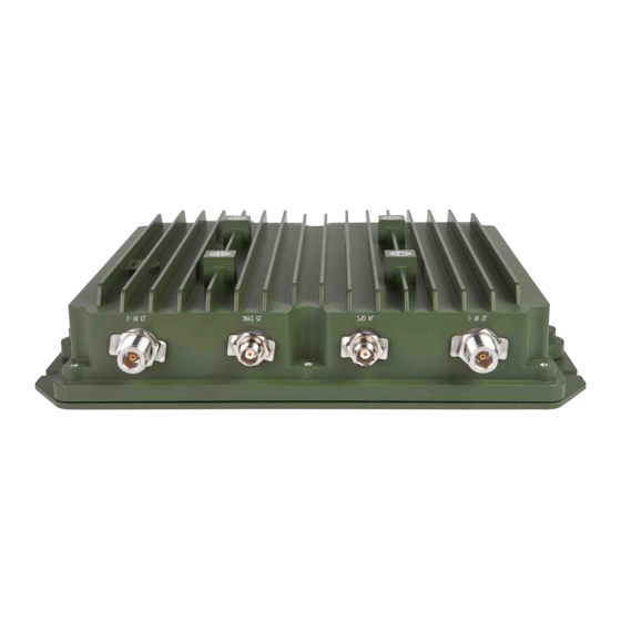
RF-7800W SYSTEM INSTALLATION J1 ETHERNET J6 ACCESSORY PER IEEE802.3 PINS J6 ACC *GROUND J1 POE SCREW *ATTACH GROUND CABLE (PURCHASED SEPARATELY) CL-0426-4200-0024 Figure 2-3. RF-7800W HCLOS Radio Bottom Ports J5 SYNC J2 RF-2 (PLANNED) J4 GPS J3 RF-1 CL-0426-4200-0023 Figure 2-4. RF-7800W HCLOS Radio Top Ports... -
Page 37: Alignment
RF-7800W SYSTEM INSTALLATION 2.4.3 Alignment Determining RSSI Using the audio buzzer works best when the installer is in close proximity to the radio. The buzzer can be controlled by logging into the radio and navigating to Wireless > Antenna Alignment Buzzer Enable. It will buzz fast for higher RSSI levels and slow for lower RSSI levels. -
Page 38: Antenna Alignment
RF-7800W SYSTEM INSTALLATION Figure 2-5. Antenna Alignment... - Page 39 RF-7800W SYSTEM INSTALLATION This page intentionally left blank. 2-10...
-
Page 40: Chapter 3 - System Administration And Configuration
RF-7800W SYSTEM ADMINISTRATION AND CONFIGURATION CHAPTER 3 SYSTEM ADMINISTRATION AND CONFIGURATION INTRODUCTION The scope of this chapter is to provide a logical grouping of system administration and configuration items relative to the following management interfaces; Graphical User Interface (GUI), Command Line Interface (CLI), and Simple Network Management Protocol (SNMP). -
Page 41: Ip Management Interface Parameters
RF-7800W SYSTEM ADMINISTRATION AND CONFIGURATION Default values of IP management interfaces are shown in Table 3-1. Table 3-1. IP Management Interface Parameters Parameter Default Value IP Address 192.168.26.2* HTTP Enabled HTTPS Enabled Telnet Enabled Enabled SNMP None * In addition to the default static IP Address, the radio uses ZeroConf technologies to automatically self-assign a second unique IP Address and a hostname and to advertise the presence of its management interfaces (HTTP and SSH). -
Page 42: Navigating User Interfaces
RF-7800W SYSTEM ADMINISTRATION AND CONFIGURATION NAVIGATING USER INTERFACES 3.3.1 Navigating the GUI Most functionality of the radio can be configured or monitored through the GUI. The information dashboard (shown Figure 3-1) can be found at the top of the page and provides important information about the radio's current status. Clicking different links in the navigation menu (shown in Figure 3-2) provides access to different detailed sections... -
Page 43: Navigating The Cli
SNMP. The latest version of the radio's Management Information Base (MIB) part number (12069-8900) can be found on the Harris Premier site (https://tcpremier.harris.com). Additional information pertaining to SNMP, including a comprehensive list of MIB objects, is available in the RF-7800W-OU47x/-OU50x SNMP Supplement (10515-0426-4040). -
Page 44: Network Interface
RF-7800W SYSTEM ADMINISTRATION AND CONFIGURATION Figure 3-3. General Information NETWORK INTERFACE The radio hosts a number of management interfaces that can be accessed via IP. This section describes the information and configuration options available for basic network configuration. See Figure 3-4. -
Page 45: Current Port Speed
RF-7800W SYSTEM ADMINISTRATION AND CONFIGURATION 3.5.1.3 Current Port Speed When the radio is set to automatically detect the Ethernet port settings, this is the port speed and duplex setting that is detected and in use. 3.5.2 Statistics The radio logs the number of Ethernet data packets that have been transmitted and received. The radio also provides the number of packets that are received with errors, which could indicate problems with the port speed or duplex settings. -
Page 46: System Configuration
RF-7800W SYSTEM ADMINISTRATION AND CONFIGURATION Figure 3-4. System Configuration... -
Page 47: Management Interfaces
RF-7800W SYSTEM ADMINISTRATION AND CONFIGURATION MANAGEMENT INTERFACES The radio can be managed over a number of IP-based interfaces. This section describes how to configure these different management interfaces. A standard web browser can be used to configure the radio over HTTP or HTTPS. Figure 3-4. -
Page 48: Ssh
RF-7800W SYSTEM ADMINISTRATION AND CONFIGURATION 3.6.2.2 GUI CLI The SSH service can be turned on and off. A host key is pre-installed, but can be overwritten with a user-generated host key. Refer to Paragraph 3.10.2. 3.6.3 Local Users (Role-Based Authentication) GUI CLI The subsections below describe Users Management Interfaces configuration parameters. -
Page 49: Users Management
RF-7800W SYSTEM ADMINISTRATION AND CONFIGURATION Figure 3-6. Users Management 3-10... -
Page 50: Snmp
RF-7800W SYSTEM ADMINISTRATION AND CONFIGURATION 3.6.4 SNMP The subsections below describe SNMP Management Interfaces configuration parameters. Click on the blue [SNMP Configuration] link shown in Figure 3-4 to access the screen. See Figure 3-7. 3.6.4.1 SNMP Versions GUI CLI SNMP v2c and SNMP v3 are the supported network management versions. Only one version can be active at a time. 3.6.4.2 Communities GUI CLI... -
Page 51: Access
RF-7800W SYSTEM ADMINISTRATION AND CONFIGURATION Figure 3-7. SNMP Configuration 3.6.5 Access GUI CLI The interface for radio management traffic and over-the-link traffic is shared on the Ethernet port. In certain situations, it may be desirable to separate the management traffic from the over-the-link traffic. This can be done within the radio by tagging management traffic with a specific 802.1Q Virtual Local Area Network (VLAN) Identification (ID). -
Page 52: Fips Mode
RF-7800W SYSTEM ADMINISTRATION AND CONFIGURATION Figure 3-8. RADIUS Configuration 3.6.7 FIPS Mode GUI CLI The radio can be placed into a high security FIPS 140-2 compliant mode when certain security configuration criteria is met. The “FIPS” text in the dashboard of the GUI links to a summary that indicates the current status of configuration parameters against the corresponding requirements. -
Page 53: Time And Location
RF-7800W SYSTEM ADMINISTRATION AND CONFIGURATION Figure 3-9. FIPS Status TIME AND LOCATION The radio has some time and location options available that can help with system troubleshooting and maintenance. Figure 3-4. 3.7.1 SNTP GUI CLI SNMP The subsections below describe Simple Network Time Protocol (SNTP) configuration parameters. All parameters for SNTP can be accessed using GUI, CLI, and SNMP interfaces. -
Page 54: Antenna Power
RF-7800W SYSTEM ADMINISTRATION AND CONFIGURATION 3.7.2.1 Antenna Power The radio can power active GPS antennas with an internal 3.3 VDC power supply. The power supply has automatic short-circuit protection that will protect the radio in the event of an incompatible or broken antenna. 3.7.2.2 Coordinates Format A number of latitude and longitude datum formats can be selected, depending on a user's preference. -
Page 55: Wireless Interface
RF-7800W SYSTEM ADMINISTRATION AND CONFIGURATION WIRELESS INTERFACE The radio has one wireless interface that consists of two RF ports. This section describes the information and configuration options available for the wireless interface. See Figure 3-14, Figure 3-15, Figure 3-16, and Figure 3-17. -
Page 56: Atpc
RF-7800W SYSTEM ADMINISTRATION AND CONFIGURATION Table 3-4. Maximum Transmit Power (Continued) 16-QAM 3/4 64-QAM 2/3 64-QAM 5/6 256-QAM 3/4 256-QAM 7/8 3.8.3.2 ATPC GUI CLI SNMP ATPC stands for Automatic Transmit Power Control and is useful for reducing co-site interference or dealing with dynamically changing link conditions. -
Page 57: Roaming
RF-7800W SYSTEM ADMINISTRATION AND CONFIGURATION without prior knowledge of the SC operating frequency. It can also be helpful when an SS is configured on multiple SCs and one of the SC is interfered with or is taken down for maintenance. 3.8.4.3 Roaming GUI CLI SNMP... -
Page 58: Channel Width
RF-7800W SYSTEM ADMINISTRATION AND CONFIGURATION Figure 3-11. Frequency Management 3.8.5 Channel Width GUI CLI SNMP The radio supports a number of different channel widths from 5 MHz to 40 MHz. Narrower channel widths allow for greater range due to improved receiver sensitivity, but the trade-off is lower throughput. Likewise, wider channel widths allow for higher throughput at the cost of link range. -
Page 59: Security
RF-7800W SYSTEM ADMINISTRATION AND CONFIGURATION NOTE This aid is not available on a SPMP SC if more than one link is present. 3.8.8 Security GUI CLI Security settings are described below. All parameters for Security can only be accessed using GUI and CLI interfaces. -
Page 60: Dfs Action
RF-7800W SYSTEM ADMINISTRATION AND CONFIGURATION NOTE DFS is currently supported for the 5.725 - 5.875 GHz band per ETSI EN 302 502. 3.8.9.1 DFS Action DFS can be configured to either turn off the radio transmitter for 30 minutes or change the radio's operating frequency. -
Page 61: Multi-Hop
RF-7800W SYSTEM ADMINISTRATION AND CONFIGURATION 3.8.10 Multi-Hop GUI CLI SNMP Sector Controllers can act as the root of a tree-like, Multi-Hop sector. In a Multi-Hop sector, subscribers are able to relay data directly to/from other subscribers that are below them in the hierarchy. Radios lower in the hierarchy (i.e. further away from the SC) are referred to as “children”, while those higher in the hierarchy are referred to as “parents”. -
Page 62: Multi-Hop Failover
RF-7800W SYSTEM ADMINISTRATION AND CONFIGURATION 3.8.10.1 Multi-Hop Failover A subscriber can be designated to support Multi-Hop Failover, which allows it to act as a temporary Failover SC if the actual SC becomes inaccessible. Once the actual SC becomes accessible again, the Failover SC reverts back to its role as an SS. -
Page 63: Wireless Configuration - Spmp Sc
RF-7800W SYSTEM ADMINISTRATION AND CONFIGURATION Figure 3-14. Wireless Configuration - SPMP SC 3-24... -
Page 64: Wireless Configuration - Sptp Sc
RF-7800W SYSTEM ADMINISTRATION AND CONFIGURATION Figure 3-15. Wireless Configuration - SPTP SC 3-25... -
Page 65: Wireless Configuration - Spmp Ss
RF-7800W SYSTEM ADMINISTRATION AND CONFIGURATION Figure 3-16. Wireless Configuration - SPMP SS 3-26... -
Page 66: Wireless Configuration - Sptp Ss
RF-7800W SYSTEM ADMINISTRATION AND CONFIGURATION Figure 3-17. Wireless Configuration - SPTP SS 3-27... -
Page 67: Subscriber Links
RF-7800W SYSTEM ADMINISTRATION AND CONFIGURATION SUBSCRIBER LINKS The overall number of configured subscribers is available, along with how many of them are currently active. An administrator can also purge all subscriber information from the radio. Click the New Link button on the Subscriber Links screen, Figure 3-22, to access the Subscriber Link Configuration screen. -
Page 68: Subscriber Mac
RF-7800W SYSTEM ADMINISTRATION AND CONFIGURATION 3.9.2.4 Subscriber MAC GUI CLI SNMP The unique MAC address of the SS radio is required when defining a new Normal Link. 3.9.2.5 STID The STID is used as a name to differentiate between Link Templates. 3.9.2.6 STID Password The STID Password provides authentication to associate with a particular STID. -
Page 69: Subscriber Link Configuration - Normal Link
RF-7800W SYSTEM ADMINISTRATION AND CONFIGURATION Figure 3-18. Subscriber Link Configuration - Normal Link 3-30... -
Page 70: Subscriber Link Configuration - Link Template
RF-7800W SYSTEM ADMINISTRATION AND CONFIGURATION Figure 3-19. Subscriber Link Configuration - Link Template 3-31... -
Page 71: Burst Rate
RF-7800W SYSTEM ADMINISTRATION AND CONFIGURATION 3.9.3.2 Burst Rate GUI CLI SNMP When adaptive modulation is not used, a single set of downlink and uplink burst rates must be configured. If the burst rate is set too high for a given link budget, it will be difficult to initiate and maintain a reliable link. When adaptive modulation is used, maximum and minimum downlink and uplink burst rates must be configured. -
Page 72: Data Smoothing
RF-7800W SYSTEM ADMINISTRATION AND CONFIGURATION 3.9.5 Data Smoothing GUI CLI This is a security option that can be activated on a per-link basis. Data Smoothing adds random data to existing user traffic in order to even out each radio’s transmission time. This can help obscure the radios from timing-related attacks, but may have an impact on maximum user throughput when turned on (e.g. -
Page 73: Broadcast/Multicast Configuration
RF-7800W SYSTEM ADMINISTRATION AND CONFIGURATION Figure 3-20. Broadcast/Multicast Configuration 3-34... -
Page 74: Statistics
RF-7800W SYSTEM ADMINISTRATION AND CONFIGURATION 3.9.8 Statistics The subsections below describe subscriber link statistics parameters. 3.9.8.1 Link Metrics GUI CLI SNMP This indicates whether RF associated with a link partner radio has been detected. As the link comes up or goes down, an SNMP trap is sent out to indicate the event. -
Page 75: Subscriber Link Status
RF-7800W SYSTEM ADMINISTRATION AND CONFIGURATION Figure 3-21. Subscriber Link Status 3-36... -
Page 76: Rf Metrics
RF-7800W SYSTEM ADMINISTRATION AND CONFIGURATION 3.9.8.2 RF Metrics GUI CLI SNMP The current RSSI and SINADR are available for each RF port and for both the SC and the SS radios. Downlink refers to the SC to SS direction, while uplink refers to the SS to SC direction. Min, mean, and max statistics for RSSI and SINADR are also available via SNMP only. -
Page 77: Subscriber Links
RF-7800W SYSTEM ADMINISTRATION AND CONFIGURATION Figure 3-22. Subscriber Links 3-38... -
Page 78: Miscellaneous Status
RF-7800W SYSTEM ADMINISTRATION AND CONFIGURATION 3.9.8.4 Miscellaneous Status Additional information related to the link is available. The MAC address of the radio linked to the radio currently being managed is displayed. A hyperlink to the linked radio’s web interface allows easy access to the other radios within a given sector. -
Page 79: Spectrum Sweep
RF-7800W SYSTEM ADMINISTRATION AND CONFIGURATION 3.10.4 Spectrum Sweep The radio comes with the ability to survey the area for potential sources of interference, including weather radar, Wi-Fi devices, high voltage power distribution, or other high-power radios. See Figure 3-23. NOTE Spectrum Sweep reduces the maximum possible user data throughput by around 10 percent. -
Page 80: Firmware Upgrade
GUI CLI Figure 3-24. The radio can be upgraded with new software that is posted to the Harris Premier site (https://tcpremier.harris.com). The upgrade files can be delivered to the radio via FTP, TFTP, SFTP, or directly via the GUI. The radio contains enough memory to store two versions of software. When a new version is uploaded, it overwrites the inactive version. -
Page 81: File Management
RF-7800W SYSTEM ADMINISTRATION AND CONFIGURATION Figure 3-24. File Management 3-42... -
Page 82: System Log
RF-7800W SYSTEM ADMINISTRATION AND CONFIGURATION 3.10.7 System Log GUI CLI SNMP Important events that occur during the course of the radio's operation are logged. Messages can be viewed either through the GUI and CLI or they can be logged to a central network SysLog server. See Figure 3-25. -
Page 83: Reboot
RF-7800W SYSTEM ADMINISTRATION AND CONFIGURATION Figure 3-26. Built-In Test 3.10.9 Reboot GUI CLI SNMP Occasionally, an Administrator may wish to remotely reboot the radio. All three management interfaces provide the ability to do this. 3-44... -
Page 84: 3.10.10 Test
RF-7800W SYSTEM ADMINISTRATION AND CONFIGURATION 3.10.10 Test An Administrator can temporarily test the configuration before saving it permanently. This is done by entering “Test” mode and applying (but not saving) settings. This can be useful if the desired configuration change could result in dropping communication to a radio that is being configured. - Page 85 RF-7800W SYSTEM ADMINISTRATION AND CONFIGURATION This page intentionally left blank. 3-46...
-
Page 86: Introduction
RF-7800W DEPLOYMENT SCENARIOS CHAPTER 4 DEPLOYMENT SCENARIOS INTRODUCTION The RF-7800W radio can be deployed in various At-the-Halt and On-the-Move scenarios, which may require different configurations. AT-THE-HALT For fixed and nomadic infrastructure deployments, the appropriate System Mode should be selected, depending on the number of required Subscriber Stations (SS). -
Page 87: Sptp
RF-7800W DEPLOYMENT SCENARIOS 4.2.2 SPTP Simple Point to Point (SPTP) supports one SS at a time per SC. See Figure 4-2. Both radios must operate on the same Frequency and Channel Width. While SPMP can be used with one SS, SPTP is optimized to operate with only one SS and therefore has slightly different behavior. - Page 88 RF-7800W DEPLOYMENT SCENARIOS Figure 4-4, the panels of the figure are described below: Panel 1 - The SS is linked to SC 1, while also seeing signal from SC 2. Panel 2 - The SS maintains a link to SC 1, while the signal from SC 2 improves and the signal from SC N becomes present.
- Page 89 RF-7800W DEPLOYMENT SCENARIOS This page intentionally left blank.
-
Page 90: Chapter 5 - Troubleshooting And Maintenance
RF-7800W TROUBLESHOOTING AND MAINTENANCE CHAPTER 5 TROUBLESHOOTING AND MAINTENANCE INTRODUCTION This chapter provides troubleshooting data necessary for fault isolation and preventive maintenance guidelines. 5.1.1 Scope of this Chapter The procedures presented in this chapter assume that a Level I fault has led the user to suspect a fault with the RF-7800W HCLOS Radio. -
Page 91: Factory Default Reset Time Frame
RF-7800W TROUBLESHOOTING AND MAINTENANCE NOTE The Telnet session must connect to the RF-7800W HCLOS Radio within approximately 20 seconds from when the radio starts responding to pings. Logging into the default IP Address will cause the unit to be reset to the factory default configuration. -
Page 92: Factory Default Reset Behavior
Symptom: The radio is not able to be managed remotely. • Solution: The default radio IP address is 192.168.26.2. A Console Port cable (Harris PN 12069-3901-Axxx) can be used to locally log into the radio to determine the IP address if the IP address has been changed. If this is not an option, the radio can be power cycled in such a way that will reset the radio's IP address to the default. -
Page 93: Wireless Troubleshooting
RF-7800W TROUBLESHOOTING AND MAINTENANCE Problem: HTTP, Telnet, and SNMPv2 are not accessible when FIPS Mode is enabled. • Symptom: Some of the radio's management interfaces are accessible, but others are not. • Solution: This is a requirement for FIPS mode. Use the HTTPS, SSH, and SNMPv3 interfaces. Problem: An untrusted SSL Certificate has been loaded into the radio. -
Page 94: Preventive Maintenance
RF-7800W TROUBLESHOOTING AND MAINTENANCE Is the link properly configured on the SC? (SPMP) Log into the SC GUI and click the name of the link in Configuration > Subscriber Links. (SPTP) Log into the SC GUI and check Configuration > Link. Subscriber MAC must be the MAC address of the SS radio for Normal Links or the STID and STID Password Hash must match that of the SS if using a Link Template. - Page 95 RF-7800W TROUBLESHOOTING AND MAINTENANCE This page intentionally left blank.
-
Page 96: Introduction
Radio. This information consists of suggested tools, parts lists, and assembly component references. ADDITIONAL SUPPORT To ensure our customers have continued success with our products, Harris provides logistics planning, spares, tools, technical documentation, training, product service, and field service. For any of these services, call 585-244-5830 (toll free: 866-264-8040), or visit the Harris Support web site at https://tcpremier.harris.com). -
Page 97: Rf-7800W-Ou500 Family Tree
RF-7800W SUPPORT DOCUMENTATION RF-7800W-OU500 HIGH CAPACITY LINE OF SIGHT SYSTEM ANCILLARY KIT, HCLOS RADIO, HCLOS RADIO GREEN 12069-3000-03 12069-3030-01 BRACKET ASSY, KIT, MIDSPAN RF COAXIAL MOUNTING CABLE INJECTOR, RADIO ANTENNA ASSY. GIGABIT, POE 12069-3800-01 12069-3810-01 12069-3940-A20 CL-0426-4200-0017 Figure 6-2. RF-7800W-OU500 Family Tree RF-7800W-OU471 HIGH CAPACITY LINE OF SIGHT... -
Page 98: Units And Cables
RF-7800W SUPPORT DOCUMENTATION RF-7800W-OU501 HIGH CAPACITY LINE OF SIGHT SYSTEM ANCILLARY KIT, HCLOS RADIO, HCLOS RADIO 12069-3000-06 12069-3030-01 BRACKET ASSY, KIT, MIDSPAN RF COAXIAL MOUNTING CABLE INJECTOR, RADIO ANTENNA ASSY. GIGABIT, POE 12069-3800-01 12069-3810-01 12069-3940-A20 CL-0426-4200-0027 Figure 6-4. RF-7800W-OU501 Family Tree 6.3.1 Units and Cables Table 6-1... -
Page 99: Attaching Hardware
RF-7800W SUPPORT DOCUMENTATION 6.3.2 Attaching Hardware Table 6-2 lists the attaching hardware supplied with the RF-7800W HCLOS Radio. Item names, descriptions, quantities, and part number are provided. Attaching hardware items are also identified in Figure 6-5. Table 6-2. Attaching Hardware Supplied with RF-7800W HCLOS Radio Letter Part Figure... -
Page 100: Antennas
RF-7800W SUPPORT DOCUMENTATION ANTENNAS Antennas for FCC Compliance at 4.9 GHz: This device has been designed to operate with the antennas listed in the following table, operating with the maximum specified gain settings. FCC 4.94 - 4.99 GHz SPTP Operation Max Tx Power (dBm) Gain Model Number... -
Page 101: Fcc 5.250-5.350 Ghz Sptp Operation
RF-7800W SUPPORT DOCUMENTATION Table 6-5. FCC 5.250-5.350 GHz SPTP Operation Model Number Gain (dBi) Description Max Tx Power (dBm) 5 MHz 10 MHz 20 MHz 40 MHz RF-7800W-AT201 10° RF-7800W-AT202 6° RF-7800W-AT203 4.4° Table 6-6. FCC 5.250-5.350 GHz SPMP Operation Model Number Gain (dBi) Description... -
Page 102: Chassis Connector Data
RF-7800W SUPPORT DOCUMENTATION FCC 5.725 - 5.850 GHz SPTP Operation Max Tx Power (dBm) Gain Model Number Description (dBi) 5 MHz 10 MHz 20 MHz 40 MHz RF-7800W-AT206 Omni RF-7800W-AT207 90° RF-7800W-AT201 10° RF-7800W-AT202 6° RF-7800W-AT203 4.4° FCC 5.725 - 5.850 GHz SPMP Operation Max Tx Power (dBm) Gain Model Number... -
Page 103: Mating Connectors
RF-7800W SUPPORT DOCUMENTATION Table 6-9. RF-7800W HCLOS Radio J6 Accessory Port (Continued) Pin # Signal Name Description Accessory Ground N/A Ground Console Rx+ Per TIA/EIA-422 Console Rx- Per TIA/EIA-422 Console Tx+ Per TIA/EIA-422 Console Tx- Per TIA/EIA-422 Console Ground N/A Per TIA/EIA-422 6.5.1 Mating Connectors Table 6-10... -
Page 104: Appendix A - Glossary
RF-7800W APPENDIX A APPENDIX A GLOSSARY GLOSSARY The following provides a glossary of terms used in this manual. Alternating Current Admin Administrator Advanced Encryption Standard Address Resolution Protocol ATPC Automatic Transmit Power Control Azimuth Horizontal direction containing bearing from Global Positioning System [GPS] or compass A binary digit that can have a value of 0 or 1. - Page 105 RF-7800W APPENDIX A Depth Abbreviation for decibel, which is one-tenth of a bel. The amount of power relative to isotropic (power equal in all directions). The amount of power relative to that represented by a 1 kHz signal which is fed one milliwatt of power into a 600 ohm resistive load; or 1 dB relative to one milliwatt, 0 dBm = 1 mW.
- Page 106 RF-7800W APPENDIX A Height HCLOS High Capacity Line-Of-Sight Half Duplex Hexagonal -H- (Continued) HTTP Hypertext Transfer Protocol (world wide web protocol) HTTPS Hypertext Transfer Protocol Secure Abbreviation for hertz, or cycles per second. Identification IEEE Institute of Electrical and Electronics Engineers Inches IN-LBS Inch-Pounds...
- Page 107 RF-7800W APPENDIX A -M- - Continued Abbreviation for Megahertz, or one million cycles per second. Management Information Base MIL-STD Military Standard MIMO Multiple Input Multiple Output milli Watt Not Applicable NEMA National Electric Manufacturers Association OFDM Orthogonal Frequency Division Multiplexing OLOS Optical Line of Sight Power Amplifier...
- Page 108 RF-7800W APPENDIX A Sector Controller SFTP SSH File Transfer Protocol SINADR Signal-to-Noise and Distortion Ratio SISO Single Input, Single Output Spatial Multiplexing SNMP Simple Network Management Protocol SNTP Simple Network Time Protocol -S- - Continued SPMP Simple Point-to-Multiple Point SPTP Simple Point-to-Point Subscriber Station Secure Shell...
- Page 109 RF-7800W APPENDIX A -V- - Continued VLAN Virtual Local Area Network VSWR Voltage Standing Wave Ratio Watts, Width Wide Area Network...
- Page 110 RF-7800W APPENDIX B APPENDIX B EU DECLARATION OF CONFORMITY...
- Page 111 RF-7800W APPENDIX B This page intentionally left blank.
- Page 112 EVALUATION FORM To the User of this Instruction Manual: HARRIS Corporation, continually evaluates its technical publications for completeness, technical accuracy, and organization. You can assist in this process by completing and returning this form. Please specify section, page number, figure or table number where applicable.
- Page 113 MAKE LAST FOLD HERE NO POSTAGE NECESSARY IF MAILED IN THE UNITED STATES BUSINESS REPLY MAIL FIRST CLASS PERMIT NO. 4033 ROCHESTER, N.Y. POSTAGE WILL BE PAID BY ADDRESSEE HARRIS CORPORATION COMMUNICATION SYSTEMS 1680 UNIVERSITY AVENUE ROCHESTER, NEW YORK 14610-1887 ATTN: TECHNICAL SERVICES...
- Page 114 │ │ Communication Systems 1680 University Ave Rochester, NY USA 14610 Tel: 585-244-5830. Fax: 585-242-4755 www.harris.com...
-
Page 115: Multi-Hop Deployment
RF-7800W DEPLOYMENT SCENARIOS SPMP SS 1 SPMP SS 1 SPMP SS 1 FREQ: A FREQ: A FREQ: A CH WID: X CH WID: X CH WID: X FAILOVER: ON FAILOVER: ON FAILOVER: ON SPMP SS 2 SPMP SS 2 SPMP SS 2 SPMP SC SPMP SC SPMP SC... -
Page 116: Roaming Deployment
RF-7800W DEPLOYMENT SCENARIOS SPMP SS SPMP SS SPMP SC 1 SPMP SC 1 SPMP SC 1 FREQ: AUTO FREQ: AUTO FREQ: A FREQ: A FREQ: A CH WID: AUTO CH WID: AUTO CH WID: X CH WID: X CH WID: X SPMP SC 2 SPMP SC 2 SPMP SC 2... -
Page 117: Rf-7800W Hclos Radio System Illustrated Parts List
RF-7800W SUPPORT DOCUMENTATION TORQUE TO APPROXIMATELY 10 FT-LBS (120 IN-LBS) (14 N-M). *ALTERNATIVELY USE D IN PLACE OF H. **ALTERNATIVELY USE C IN PLACE OF I. + MAST MUST BE 1.5 INCHES TO 4.0 INCHES OUTER DIAMETER. LETTER DESCRIPTION DESCRIPTION DESCRIPTION DESCRIPTION DESCRIPTION...
Need help?
Do you have a question about the RF-7800W-OU470 and is the answer not in the manual?
Questions and answers