Table of Contents
Advertisement
Quick Links
PUBLICATION NUMBER: 10514-0426-4220
FEBRUARY 2016
Rev. -
RF-7800W-OU49x
MULTIMISSION HCLOS
RADIO
INSTALLATION/
OPERATION
MANUAL
This information is controlled by the U.S. Department of Commerce Export Administration Regulations 15
CFR 730-774, ECCN EAR99. Information contained herein is property of Harris Corporation and may not be
copied or reproduced by any means, without prior written permission.
Advertisement
Table of Contents
Troubleshooting

Related Manuals for Harris RF-7800W-OU49 series


Summary of Contents for Harris RF-7800W-OU49 series
- Page 1 This information is controlled by the U.S. Department of Commerce Export Administration Regulations 15 CFR 730-774, ECCN EAR99. Information contained herein is property of Harris Corporation and may not be copied or reproduced by any means, without prior written permission.
- Page 2 Harris Product Service: Phone (585) 242-3561, Toll-free (866) 264-8040, Fax: 585-242-4483 Harris will repair or replace the defective equipment or part and pay for its return to you, provided the repair or replacement is due to a cause covered by this warranty.
- Page 4 This information is controlled by the U.S. Department of Commerce Export Administration Regulations 15 CFR 730-774, ECCN EAR99. Information and descriptions contained herein are the property of Harris Corporation. Such information and descriptions may not be copied or reproduced by any means, or disseminated or distributed without the express prior written permission of Harris Corporation, Communication Systems, 1680 University Avenue, Rochester, New York 14610-1887.
-
Page 6: Table Of Contents
RF-7800W TABLE OF CONTENTS TABLE OF CONTENTS Paragraph Page CHAPTER 1 – GENERAL INFORMATION INTRODUCTION ..........SYSTEM DESCRIPTION . - Page 7 RF-7800W TABLE OF CONTENTS TABLE OF CONTENTS – Continued Paragraph Page CHAPTER 3 – SYSTEM ADMINISTRATION AND CONFIGURATION - CONTINUED 3.5.1.3 Current Port Speed ..........3.5.2 Statistics .
- Page 8 RF-7800W TABLE OF CONTENTS TABLE OF CONTENTS – Continued Paragraph Page CHAPTER 3 – SYSTEM ADMINISTRATION AND CONFIGURATION - CONTINUED 3.8.3.2 Statistics ........... . . 3-15 3.8.4 Frequency .
- Page 9 RF-7800W TABLE OF CONTENTS TABLE OF CONTENTS – Continued Paragraph Page CHAPTER 3 – SYSTEM ADMINISTRATION AND CONFIGURATION - CONTINUED 3.9.7.4 Miscellaneous Status ......... . . 3-31 3.10 MAINTENANCE .
- Page 10 RF-7800W TABLE OF CONTENTS LIST OF FIGURES Figure Page RF-7800W HCLOS Radio Installed With One-Foot Panel MIMO Antenna . . PoE Injector Kit - All Regions ........RF-7800W HCLOS Radio Dimensions .
- Page 11 RF-7800W TABLE OF CONTENTS LIST OF TABLES Table Page RF-7800W HCLOS Radio Ancillary Items ......RF-7800W HCLOS Radio Specifications .
- Page 12 RF-7800W SAFETY SUMMARY SAFETY SUMMARY INTRODUCTION All operators and maintenance personnel must observe the following safety precautions during operation and maintenance of this equipment. Specific warnings and cautions are provided in the manual and at the end of this Safety Summary. Warnings, Cautions, and Notes appear before various steps in the manual and will be used as follows: •...
- Page 13 RF-7800W SAFETY SUMMARY Personnel must react when someone is being electrically shocked. Perform the following steps: Shut off power. Call for help. Administer first aid if qualified. Under no circumstances should a person come directly in contact with the body unless the power has been removed.
- Page 14 RF-7800W SAFETY SUMMARY USE CARE HANDLING HEAVY EQUIPMENT Never attempt to lift large assemblies or equipment without knowing their weight. Use enough personnel or a mechanical lifting device to properly handle the item without causing personal injury. HEED WARNINGS AND CAUTIONS Specific warnings and cautions are provided to ensure the safety and protection of personnel and equipment.
- Page 15 RF-7800W SAFETY SUMMARY This page intentionally left blank.
-
Page 16: Chapter 1 - General Information
RF-7800W GENERAL INFORMATION CHAPTER 1 GENERAL INFORMATION INTRODUCTION The scope and overall intent of this manual is to help the user understand how to install and operate the RF-7800W High Capacity Line of Sight (HCLOS) radio. SYSTEM DESCRIPTION The RF-7800W HCLOS broadband Ethernet radio is designed to be used in multiple mission configurations to provide a seamless extension of Ethernet Local Area Networks (LANs) and Wide Area Networks (WANs). -
Page 17: Ancillary Items
RF-7800W GENERAL INFORMATION RF-7800W-AT201 ONE-FOOT ANTENNA (PURCHASED SEPARATELY) MAST OR TOWER PIPE (PURCHASED SEPARATELY) RF-7800W HCLOS RADIO BRACKET AND RF CABLES CL-0426-4220-0001 (PURCHASED SEPARATELY) Figure 1-1. RF-7800W HCLOS Radio Installed With One-Foot Panel MIMO Antenna 1.2.1 Ancillary Items Refer to Table 1-1. -
Page 18: Poe Injector Kit
RF-7800W GENERAL INFORMATION 1.2.2 PoE Injector Kit Figure 1-2. The indoor-mounted Power over Ethernet (PoE) Injector is an in-line power injector that provides operational power for the radio as well as connection to the network. AC power plug adapters are included for USA National Electric Manufacturers Association (NEMA) 5-15R to Australia/New Zealand, UK, and Europe. -
Page 19: Poe Injector Kit - All Regions
RF-7800W GENERAL INFORMATION AC POWER CABLE (USA) NEMA 5-15R TO UK BS 1363 ADAPTER NEMA 5-15R TO EUROPE CEE 7/7 ADAPTER USA NEMA 5-15R TO AUSTRALIA/NEW ZEALAND ADAPTER PoE INJECTOR (CONNECT TO RF-7800W RADIO) (CONNECT TO ETHERNET NETWORK) (DATA) (DATA AND POWER) PoE INJECTOR PORTS - FRONT VIEW DETAIL CL-0426-4200-0019 Figure 1-2. -
Page 20: Equipment Description
RF-7800W GENERAL INFORMATION EQUIPMENT DESCRIPTION The radio is housed in a weatherproof aluminum alloy case and is mounted outdoors to the optional mast mount bracket. The main unit contains all of the RF and digital electronics. Power delivery is accomplished via an IEEE 802.3at PoE standard power injector. -
Page 21: Radio Mounting Hole Pattern
RF-7800W GENERAL INFORMATION 1.3.2 Radio Mounting Hole Pattern Figure 1-4 shows the RF-7800W HCLOS radio mounting hole pattern. 3.93 IN (10 CM) 2.87 IN (7.3 CM) 3.93 IN (10 CM) 10.92 IN (27.7 CM) CL-0426-4200-0025 Figure 1-4. RF-7800W HCLOS Radio Mounting Hole Pattern... -
Page 22: Specifications
RF-7800W GENERAL INFORMATION SPECIFICATIONS Table 1-2 provides specifications for the RF-7800W HCLOS Radio. Table 1-2. RF-7800W HCLOS Radio Specifications Function Specification GENERAL Frequency Range 5.725-5.875 GHz Power Requirements IEEE 802.3at Compliant PSE, 30W Maximum WIRELESS Wireless Transmission Time Division Duplexing (TDD) Orthogonal Frequency Division Multiplexing (ODFM), 2x2 MIMO Capable, Space-Time Coding (STC), Spatial Multiplexing (SMX) Uncoded Data Rate... -
Page 23: Fcc Notices (For Deployments Within The Usa)
Connect the equipment into an outlet on a circuit different from that to which the receiver is connected. • Consult the dealer or an experienced radio/TV technician for help. FCC Information to Users (Part 15.21): WARNING Changes or modifications not expressly approved by Harris Corporation could void the user’s authority to operate the equipment. -
Page 24: Chapter 2 - System Installation
2.1.2 Link Availability Harris provides a free tool to users that wish to perform a simple evaluation of a single RF-7800W radio link under ideal environmental and terrain conditions. The Link Budget Tool (available via the Harris Premier site https://rfcommpremier.harris.com) provides a rudimentary calculation of annual Link Availability (Uptime) and can help users choose the right antenna for their specific installation. -
Page 25: Installation Requirements
(Harris PN 12069-0030-Axxx and 12069-0031-Axxx) • Dual-linear (V/H) polarized antennas in order to operate at full throughput capacity. (Harris PN RF-7800W- AT2XX) The installation site should be free from major twist or sway under wind loading. A higher mounting location will help guarantee better Line of Sight (LOS) conditions, but can increase the risk of damage due to lightning. -
Page 26: Configure The Subscriber Stations
RF-7800W SYSTEM INSTALLATION 2.3.2 Configure the Subscriber Stations Select Wireless Configuration and ensure that the Frequency and Channel Size are configured the same on all linked radios. Change the Tx Power, if necessary. Select Apply & Save All. Select System Configuration and ensure that each radio has a unique IP address so that they can be individually accessible over the wireless link. -
Page 27: Installation
RF-7800W SYSTEM INSTALLATION INSTALLATION 2.4.1 Hardware Installation Mounting the Radio The radio's ancillary kit comes with a bracket that is designed to mount the radio and an antenna to a vertical pipe or mast with a diameter of 1.5 to 4.0 inches. The radio can be mounted on either side of the bracket but should be installed with the Ethernet port facing the ground (see Figure 2-1). -
Page 28: Radio And Antenna Mounting
RF-7800W SYSTEM INSTALLATION RF-7800W-AT201 ONE-FOOT ANTENNA (PURCHASED SEPARATELY) SYNC RF CABLE (PURCHASED SEPARATELY) RF-7800W HCLOS RADIO RF CABLE (PURCHASED SEPARATELY) MAST MOUNT ETHERNET CABLE BRACKET (PURCHASED (PURCHASED SEPARATELY) SEPARATELY) GROUND CABLE (PURCHASED SEPARATELY) CL-0426-4220-0009 Figure 2-1. Radio and Antenna Mounting... -
Page 29: Connecting Cables
RF-7800W SYSTEM INSTALLATION 2.4.2 Connecting Cables Grounding (recommended) Connect the ring terminal of a grounding wire (Item 8) to the radio's ground terminal (see Figure 2-2) using a #2 Phillips driver (Item 3). Connect the other end to a single, central grounding point. Avoid sharp bends in the wire. -
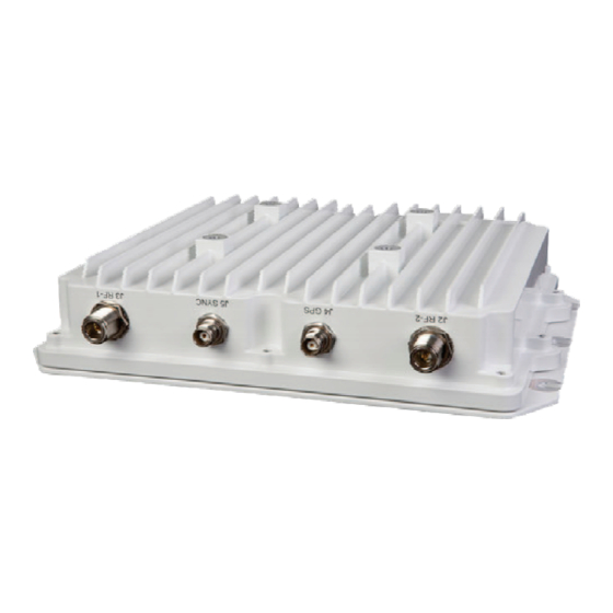
Page 30: Rf-7800W Hclos Radio Bottom Ports
RF-7800W SYSTEM INSTALLATION J1 ETHERNET J6 ACCESSORY PER IEEE802.3 PINS J6 ACC *GROUND J1 POE SCREW *ATTACH GROUND CABLE (PURCHASED SEPARATELY) CL-0426-4200-0024 Figure 2-2. RF-7800W HCLOS Radio Bottom Ports J5 SYNC J2 RF-2 (PLANNED) J4 GPS J3 RF-1 CL-0426-4200-0023 Figure 2-3. RF-7800W HCLOS Radio Top Ports... -
Page 31: Alignment
RF-7800W SYSTEM INSTALLATION 2.4.3 Alignment Determining RSSI Using the audio buzzer works best when the installer is in close proximity to the radio. The buzzer can be controlled by logging into the radio and navigating to Wireless > Antenna Alignment Buzzer Enable. It will buzz fast for higher RSSI levels and slow for lower RSSI levels. -
Page 32: Chapter 3 - System Administration And Configuration
RF-7800W SYSTEM ADMINISTRATION AND CONFIGURATION CHAPTER 3 SYSTEM ADMINISTRATION AND CONFIGURATION INTRODUCTION The scope of this chapter is to provide a logical grouping of system administration and configuration items relative to the following management interfaces; Graphical User Interface (GUI), Command Line Interface (CLI), and Simple Network Management Protocol (SNMP). -
Page 33: Ip Management Interface Parameters
RF-7800W SYSTEM ADMINISTRATION AND CONFIGURATION Default values of IP management interfaces are shown in Table 3-1. Table 3-1. IP Management Interface Parameters Parameter Default Value IP Address 192.168.26.2* HTTP Enabled HTTPS Enabled Telnet Enabled Enabled SNMP None * In addition to the default static IP Address, the radio uses ZeroConf technologies to automatically self-assign a second unique IP Address and a hostname and to advertise the presence of its management interfaces (HTTP and SSH). -
Page 34: Navigating User Interfaces
RF-7800W SYSTEM ADMINISTRATION AND CONFIGURATION NAVIGATING USER INTERFACES 3.3.1 Navigating the GUI Most functionality of the radio can be configured or monitored through the GUI. The information dashboard (shown Figure 3-1) can be found at the top of the page and provides important information about the radio's current status. Clicking different links in the navigation menu (shown in Figure 3-2) provides access to different detailed sections... -
Page 35: Navigating The Cli
GUI and/or the CLI are also available via SNMP. In the interest of security, functions related to encryption certificates, keys and secure management interfaces are not accessible via SNMP. The latest version of the radio's Management Information Base (MIB) part number (12069-8900) can be found on the Harris Premier site (https://rfcommpremier.harris.com). -
Page 36: Network Interface
RF-7800W SYSTEM ADMINISTRATION AND CONFIGURATION Figure 3-3. General Information NETWORK INTERFACE The radio hosts a number of management interfaces that can be accessed via IP. This section describes the information and configuration options available for basic network configuration. See Figure 3-4. -
Page 37: Addressing
RF-7800W SYSTEM ADMINISTRATION AND CONFIGURATION 3.5.2.1 Addressing GUI CLI SNMP The subsections below describe Addressing configuration parameters. All parameters for Addressing can be accessed using GUI, CLI, and SNMP interfaces. 3.5.2.2 IP Address This is the IP address of the radio's management interfaces. The factory default address is 192.168.26.2. 3.5.2.3 Subnet Mask This is the subnet mask of the radio's management interfaces. -
Page 38: System Configuration
RF-7800W SYSTEM ADMINISTRATION AND CONFIGURATION Figure 3-4. System Configuration... -
Page 39: Management Interfaces
RF-7800W SYSTEM ADMINISTRATION AND CONFIGURATION MANAGEMENT INTERFACES The radio can be managed over a number of IP-based interfaces. This section describes how to configure these different management interfaces. A standard web browser can be used to configure the radio over HTTP or HTTPS. Figure 3-4. -
Page 40: Adding A User Account
RF-7800W SYSTEM ADMINISTRATION AND CONFIGURATION for Role-Based authentication, defined by the account groups. If User-Based authentication is required, a separate RADIUS server can be used to expand the number of possible user accounts beyond the five account limit. 3.6.3.2 Adding a User Account User accounts can be added to the list by members of the Admin group. -
Page 41: Snmp
RF-7800W SYSTEM ADMINISTRATION AND CONFIGURATION 3.6.4 SNMP The subsections below describe SNMP Management Interfaces configuration parameters. Click on the blue [SNMP Configuration] link shown in Figure 3-4 to access the screen. See Figure 3-6. 3.6.4.1 SNMP Versions GUI CLI SNMP v2c and SNMP v3 are the supported network management versions. Only one version can be active at a time. 3.6.4.2 Communities GUI CLI... -
Page 42: Access
RF-7800W SYSTEM ADMINISTRATION AND CONFIGURATION 3.6.5 Access GUI CLI The interface for radio management traffic and over-the-link traffic is shared on the Ethernet port. In certain situations, it may be desirable to separate the management traffic from the over-the-link traffic. This can be done within the radio by tagging management traffic with a specific 802.1Q Virtual Local Area Network (VLAN) Identification (ID). -
Page 43: Fips Mode
RF-7800W SYSTEM ADMINISTRATION AND CONFIGURATION 3.6.7 FIPS Mode GUI CLI The radio can be placed into a high security FIPS Mode when certain security configuration criteria are met. The “FIPS Status” text in the dashboard of the GUI links to a summary that indicates the current status of configuration parameters against the corresponding requirements. -
Page 44: Gps Status
RF-7800W SYSTEM ADMINISTRATION AND CONFIGURATION 3.7.2.4 GPS Status A more detailed overview of the internal GPS module's state can be obtained, which displays the radio's altitude, GPS-recovered time, and lots of information about the satellites in view of the GPS antenna. The radio can be configured to send an SNMP trap if the number of GPS Satellites in view is low, or if the number of GPS satellites in view has been low for 12 hours. -
Page 45: Maximum Transmit Power - Radio Type T502C
RF-7800W SYSTEM ADMINISTRATION AND CONFIGURATION Table 3-4. Maximum Transmit Power - Radio Type T502C Modulation/ Max Tx Power (dBm) Coding Rate BPSK 1/2 QPSK 1/2 QPSK 3/4 16-QAM 1/2 16-QAM 3/4 64-QAM 2/3 64-QAM 3/4 64-QAM 5/6 256-QAM 3/4 256-QAM 7/8 Table 3-5. -
Page 46: Statistics
RF-7800W SYSTEM ADMINISTRATION AND CONFIGURATION 3.8.3.2 Statistics CLI SNMP The actual transmit power depends on a number of things, including Automatic Transmit Power Control (ATPC) settings other dynamic link conditions. The current transmit power and other related statistics are logged. 3.8.4 Frequency The frequency settings are described below. -
Page 47: Antenna Alignment
RF-7800W SYSTEM ADMINISTRATION AND CONFIGURATION 3.8.7 Antenna Alignment GUI CLI SNMP The radio provides aids to aligning the antenna to a remote radio. Radios can be configured to emit a chirping sound (referred to as a buzzer) that chirps faster with higher average Receive Signal Strength Indication (RSSI). The radio GUI also contains a page that refreshes every second and displays the RSSI and Signal-to-Noise and Distortion Ratio (SINADR) for the link. -
Page 48: Interference Mitigation
RF-7800W SYSTEM ADMINISTRATION AND CONFIGURATION power, radios will increase their power in order to meet the target RSSI. When link conditions improve, radios reduce their power accordingly. All radios will respect the configured maximum transmit power setting. 3.8.10 Interference Mitigation GUI CLI SNMP Interference Mitigation settings are described below. -
Page 49: Eim Auto Channel Change
RF-7800W SYSTEM ADMINISTRATION AND CONFIGURATION 3.8.10.4 EIM Auto Channel Change When interference is detected, the radio has the option of initiating all radios to jump to a new, potentially cleaner operating frequency. There is minimal downtime when this occurs successfully, but sometimes the radios may jump to another interference situation. -
Page 50: Wireless Configuration - Spmp Sc
RF-7800W SYSTEM ADMINISTRATION AND CONFIGURATION Figure 3-8. Wireless Configuration - SPMP SC 3-19... -
Page 51: Wireless Configuration - Sptp Sc
RF-7800W SYSTEM ADMINISTRATION AND CONFIGURATION Figure 3-9. Wireless Configuration - SPTP SC 3-20... -
Page 52: Wireless Configuration - Spmp Ss
RF-7800W SYSTEM ADMINISTRATION AND CONFIGURATION Figure 3-10. Wireless Configuration - SPMP SS 3-21... -
Page 53: Wireless Configuration - Sptp Ss
RF-7800W SYSTEM ADMINISTRATION AND CONFIGURATION Figure 3-11. Wireless Configuration - SPTP SS 3-22... -
Page 54: Subscriber Links
RF-7800W SYSTEM ADMINISTRATION AND CONFIGURATION SUBSCRIBER LINKS The overall number of configured subscribers is available, along with how many of them are currently active. An administrator can also purge out all of the subscriber information from the radio. Click on New Subscriber Link under Provisioning in the Navigation Menu (Figure 3-2) to access the Subscriber Link Configuration screen. -
Page 55: Subscriber Ip
RF-7800W SYSTEM ADMINISTRATION AND CONFIGURATION 3.9.2.5 Subscriber IP GUI SNMP Once the SS radio has successfully linked up with the SC, the SS radio's IP address is made available in the link details as a convenient way to quickly log into the radio's management GUI. 3.9.2.6 Modulation and Coding Rates Modulation and Coding rate settings are described below. -
Page 56: Subscriber Link Configuration - Normal Link
RF-7800W SYSTEM ADMINISTRATION AND CONFIGURATION Figure 3-12. Subscriber Link Configuration - Normal Link 3-25... -
Page 57: Subscriber Link Configuration - Link Templates
RF-7800W SYSTEM ADMINISTRATION AND CONFIGURATION Figure 3-13. Subscriber Link Configuration - Link Templates 3-26... -
Page 58: Burst Rate
RF-7800W SYSTEM ADMINISTRATION AND CONFIGURATION 3.9.2.8 Burst Rate GUI CLI SNMP When adaptive modulation is not used, a single set of downlink and uplink burst rates must be configured. If the burst rate is set too high for a given link budget, it will be difficult to initiate and maintain a reliable link. When adaptive modulation is used, maximum and minimum downlink and uplink burst rates must be configured. -
Page 59: Data Smoothing
RF-7800W SYSTEM ADMINISTRATION AND CONFIGURATION 3.9.4 Data Smoothing GUI CLI This is a security option that can be activated on a per-link basis. Data Smoothing adds random data to existing user traffic in order to even out each radio’s transmission time. This can help obscure the radios from timing-related attacks, but may have an impact on maximum user throughput when turned on. -
Page 60: Broadcast/Multicast Configuration
RF-7800W SYSTEM ADMINISTRATION AND CONFIGURATION Figure 3-14. Broadcast/Multicast Configuration 3-29... -
Page 61: Statistics
RF-7800W SYSTEM ADMINISTRATION AND CONFIGURATION 3.9.7 Statistics The subsections below describe subscriber link statistics parameters. 3.9.7.1 Link Metrics GUI CLI SNMP This indicates whether RF associated with a link partner radio has been detected. As the link comes up or goes down, an SNMP trap is sent out to indicate the event. -
Page 62: Rf Metrics
RF-7800W SYSTEM ADMINISTRATION AND CONFIGURATION 3.9.7.2 RF Metrics GUI CLI SNMP The current RSSI and SINADR are available for each RF port and for both the SC and the SS radios. Downlink refers to the SC to SS direction, while uplink refers to the SS to SC direction. Min, mean, and max statistics for RSSI and SINADR are also available via SNMP only. -
Page 63: Spectrum Sweep
GUI CLI SNMP Figure 3-18. The radio can be upgraded with new software that is posted to the Harris Premier site (https://rfcommpremier.harris.com). The upgrade files can be delivered to the radio via initiated FTP or TFTP transactions, or directly via the GUI. The radio contains enough memory to store two versions of software. When a new version is uploaded, it overwrites the inactive version. -
Page 64: File Management
RF-7800W SYSTEM ADMINISTRATION AND CONFIGURATION Figure 3-18. File Management 3-33... -
Page 65: System Log
RF-7800W SYSTEM ADMINISTRATION AND CONFIGURATION 3.10.6 System Log GUI CLI SNMP Important events that occur during the course of the radio's operation are logged. Messages can be viewed either through the GUI and CLI or they can be logged to a central network SysLog server. See Figure 3-19. -
Page 66: Test
RF-7800W SYSTEM ADMINISTRATION AND CONFIGURATION 3.10.9 Test An Administrator can temporarily test the configuration before saving it permanently. This is done by entering “Test” mode and applying (but not saving) settings. This can be useful if the desired configuration change could result in dropping communication to a radio that is being configured. - Page 67 RF-7800W SYSTEM ADMINISTRATION AND CONFIGURATION This page intentionally left blank. 3-36...
-
Page 68: Chapter 4 - Troubleshooting And Maintenance
RF-7800W TROUBLESHOOTING AND MAINTENANCE CHAPTER 4 TROUBLESHOOTING AND MAINTENANCE INTRODUCTION This chapter provides troubleshooting data necessary for fault isolation and preventive maintenance guidelines. 4.1.1 Scope of this Chapter The procedures presented in this chapter assume that a Level I fault has led the user to suspect a fault with the RF-7800W HCLOS Radio. -
Page 69: Factory Default Reset Time Frame
RF-7800W TROUBLESHOOTING AND MAINTENANCE NOTE The Telnet session must connect to the RF-7800W HCLOS Radio within approximately 20 seconds from when the radio starts responding to pings. Logging into the default IP Address will cause the unit to be reset to the factory default configuration. -
Page 70: Factory Default Reset Behavior
Symptom: The radio is not able to be managed remotely. • Solution: The default radio IP address is 192.168.26.2. A Console Port cable (Harris PN 12069-3901-Axxx) can be used to locally log into the radio to determine the IP address if the IP address has been changed. If this is not an option, the radio can be power cycled in such a way that will reset the radio's IP address to the default. -
Page 71: Wireless Troubleshooting
RF-7800W TROUBLESHOOTING AND MAINTENANCE Problem: HTTP, Telnet, and SNMPv2 are not accessible when FIPS Mode is enabled. • Symptom: Some of the radio's management interfaces are accessible, but others are not. • Solution: This is a requirement for FIPS mode. Use the HTTPS, SSH, and SNMPv3 interfaces. •... -
Page 72: Preventive Maintenance
RF-7800W TROUBLESHOOTING AND MAINTENANCE Is the operating channel free from interference? Log into the GUI and click Utilities > Spectrum Sweep. Run a sweep with a step of ½ the channel size, ~100 MHz below and above the Channel Frequency. Disable the Sector Controller (SC) transmitter while sweeping on the Subscriber Station (SS). - Page 73 RF-7800W TROUBLESHOOTING AND MAINTENANCE This page intentionally left blank.
-
Page 74: Chapter 5 - Support Documentation
Radio. This information consists of suggested tools, parts lists, and assembly component references. ADDITIONAL SUPPORT To ensure our customers have continued success with our products, Harris provides logistics planning, spares, tools, technical documentation, training, product service, and field service. For any of these services, call 585-244-5830 (toll free: 866-264-8040), or visit the Harris Support web site at https://rfcommpremier.harris.com). -
Page 75: Attaching Hardware
RF-7800W SUPPORT DOCUMENTATION Table 5-1. RF-7800W HCLOS Unit and Cable Figure Description CAGE Part Number Number HCLOS Radio 14304 12069-3000-07 (OU492) Figure 5-2 Ancillary Kit, Broadband Ethernet 14304 12069-3030-02 Figure 5-2 Radio Kit, MidSpan Injector - Power 14304 12069-3800-01 Figure 5-2 over Ethernet (PoE), Gigabit (with Plug Adapters and Power Cord) -
Page 76: Antennas
RF-7800W SUPPORT DOCUMENTATION ANTENNAS Antennas for FCC Compliance at 5.8 GHz: This device has been designed to operate with the antennas listed in the following table, operating with the maximum specified gain settings. 5.725 - 5.850 GHz SPTP Operation Max Tx Power (dBm) Gain Description (dBi) -
Page 77: Mating Connectors
Certain features are not included in the core feature set, but may be purchased separately. Refer to Table 5-5 for a list of optional features supported by this software version. These features may be ordered separately through the Harris Premier site (https://rfcommpremier.harris.com). Table 5-5. Optional Features Name Description... -
Page 78: Appendix A - Glossary
RF-7800W APPENDIX A APPENDIX A GLOSSARY GLOSSARY The following provides a glossary of terms used in this manual. Alternating Current Admin Administrator Advanced Encryption Standard Address Resolution Protocol ATPC Automatic Transmit Power Control Azimuth Horizontal direction containing bearing from Global Positioning System [GPS] or compass A binary digit that can have a value of 0 or 1. - Page 79 RF-7800W APPENDIX A -D- (Continued) The amount of power relative to isotropic (power equal in all directions). The amount of power relative to that represented by a 1 kHz signal which is fed one milliwatt of power into a 600 ohm resistive load; or 1 dB relative to one milliwatt, 0 dBm = 1 mW.
- Page 80 RF-7800W APPENDIX A -H- (Continued) HTTP Hypertext Transfer Protocol (world wide web protocol) HTTPS Hypertext Transfer Protocol Secure Abbreviation for hertz, or cycles per second. Identification IEEE Institute of Electrical and Electronics Engineers Inches IN-LBS Inch-Pounds Inline Network Encryptor Internet Protocol Abbreviation for kilogram, or one thousand grams.
- Page 81 RF-7800W APPENDIX A Not Applicable NEMA National Electric Manufacturers Association ODFM Orthogonal Frequency Division Multiplexing OLOS Optical Line of Sight Personal Computer Antenna Packing Checklist Peak Information Rate Phase Lock Loop Point-to-Multiple Points Power Over Ethernet Point-to-Point Quadrature Amplitude Modulation Quality of Service QPSK Quadrature Phase-Shift Keying...
- Page 82 RF-7800W APPENDIX A -S- - Continued SPMP Simple Point-to-Multiple Point SPTP Simple Point-to-Point Subscriber Station Secure Shell Secure Socket Layer Space-Time Coding STID Station Template Identifier Time Division Duplexing TELNET Telecommunication Network Traffic Flow Security TFTP Trivial File Transfer Protocol Tx, TX Transmit Uncoded Burst Rate...
- Page 83 RF-7800W APPENDIX A This page intentionally left blank.
- Page 84 EVALUATION FORM To the User of this Instruction Manual: HARRIS Corporation, continually evaluates its technical publications for completeness, technical accuracy, and organization. You can assist in this process by completing and returning this form. Please specify section, page number, figure or table number where applicable.
- Page 85 MAKE LAST FOLD HERE NO POSTAGE NECESSARY IF MAILED IN THE UNITED STATES BUSINESS REPLY MAIL FIRST CLASS PERMIT NO. 4033 ROCHESTER, N.Y. POSTAGE WILL BE PAID BY ADDRESSEE HARRIS CORPORATION COMMUNICATION SYSTEMS 1680 UNIVERSITY AVENUE ROCHESTER, NEW YORK 14610-1887 ATTN: TECHNICAL SERVICES...
- Page 86 │ │ Communication Systems 1680 University Ave Rochester, NY USA 14610 Tel: 585-244-5830. Fax: 585-242-4755 www.harris.com...
-
Page 87: Rf-7800W Hclos Radio System Illustrated Parts List
RF-7800W SUPPORT DOCUMENTATION TORQUE TO APPROXIMATELY 10 FT-LBS (120 IN-LBS) (14 N-M). *ALTERNATIVELY USE D IN PLACE OF H. **ALTERNATIVELY USE C IN PLACE OF I. + MAST MUST BE 1.5 INCHES TO 4.0 INCHES OUTER DIAMETER. † BRACKET AND ASSOCIATED HARDWARE PURCHASED SEPARATELY. ETTER ESCRIPTION PART NUMBER...
Need help?
Do you have a question about the RF-7800W-OU49 series and is the answer not in the manual?
Questions and answers