Table of Contents
Advertisement
Quick Links
Download this manual
See also:
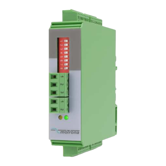
Operating Manual
control – motion –
for Incremental Encoder Signals
Universal encoder interface, applicable as level converter, encoder splitter and
encoder cross switch
Two encoder inputs A, B, Z and /A, /B, /Z, adjustable to either TTL/RS422 level
or to HTL (10-30 volts) level
Two signal outputs A, B, Z and /A, /B, /Z, likewise adjustable to either TTL/RS422
or HTL (10-30 volts) level
High frequency range ( 1 MHz )
Contactless and bounce-free switch-over between the encoder channels, by remote
control signals
Power supply 12-30 volts DC, auxiliary output 5 volts for encoder supply
GV21002d_e.doc / Sep-13
interface
GV 210
Cross Switcher and Splitter
A, /A, B, /B, Z, /Z
A, /A, B, /B, Z, /Z
Operating Instructions
Control 1
In1
In2
Control 2
motrona GmbH
Zwischen den Wegen 32
78239 Rielasingen - Germany
Tel. +49 (0)7731-9332-0
Fax +49 (0)7731-9332-30
info@motrona.com
www.motrona.de
A, /A, B, /B, Z, /Z
Out1
Out2
A, /A, B, /B, Z, /Z
Page 1 / 11
Advertisement
Table of Contents

Related Manuals for Motrona GV 210


Summary of Contents for Motrona GV 210
-
Page 1: Operating Instructions
78239 Rielasingen - Germany Tel. +49 (0)7731-9332-0 Fax +49 (0)7731-9332-30 control – motion – interface info@motrona.com www.motrona.de GV 210 Cross Switcher and Splitter for Incremental Encoder Signals A, /A, B, /B, Z, /Z Control 1 A, /A, B, /B, Z, /Z Out1... -
Page 2: Safety Instructions
Safety Instructions This manual is an essential part of the unit and contains important hints about function, correct handling and commissioning. Non-observance can result in damage to the unit or the machine, or even in injury to persons using the equipment ! ... - Page 3 Table of Contents 1. Applications ....................4 1.1. Dual level converter ....................4 1.2. Encoder splitter (dual output)...................4 1.3. Encoder signal switcher ...................5 2. Connection Diagram ..................6 2.1. Power supply ......................6 2.2. Control inputs ......................6 2.3. Encoder inputs......................6 2.4. Asymmetric TTL Inputs.....................7 2.5.
-
Page 4: Applications
1. Applications 1.1. Dual level converter RS422 or Control 1 HTL 10-30V HTL 10-30V = LOW or RS422 A, /A, B, /B, Z, /Z A, /A, B, /B, Z, /Z Out1 Out2 A, /A, B, /B, Z, /Z A, /A, B, /B, Z, /Z RS422 or HTL 10-30V Control 2... -
Page 5: Encoder Signal Switcher
1.3. Encoder signal switcher RS422 or Control 1 HTL 10-30V HTL 10-30V LO = In1, Hi = In2 or RS422 A, /A, B, /B, Z, /Z A, /A, B, /B, Z, /Z Out1 Out2 A, /A, B, /B, Z, /Z A, /A, B, /B, Z, /Z RS422 or HTL 10-30V... -
Page 6: Connection Diagram
2. Connection Diagram Output 1 Input 1 8 7 6 5 4 3 2 1 9 8 7 6 5 4 3 2 1 Terminal strip 8-pos. Terminal strip 9-pos. Connectors are mechanically coded and therefore not Control 1 interchangeable Control 2 Power supply Terminal strip 8-pos. -
Page 7: Asymmetric Ttl Inputs
A, B and Z may at any time also be independent single signals, e.g. from proximities, photocells etc. Since the level of every channel is selected individually (see DIL-switch), it is possible to use different levels on the inputs. Consequently it is e.g. possible to take the position information from the A, /A, B and /B channels of a RS422 encoder, but to add the corresponding Z index pulse as a HTL signal from a remote photocell With HTL signals, the switching threshold lies between 6.5 and 8 volts. -
Page 8: The Front Leds
3. The Front LEDs The green LED is lit as soon as a power supply voltage is applied to the unit. The yellow LED indicates the state of the Control inputs and the basic function of the unit: Yellow LED off: Control1 and Control2 are either both LOW or both HIGH at the same time. In this case the unit operates as a splitter (both outputs are connected to the same input) Yellow LED on: Control1 and Control2 have different states. -
Page 9: Switch Settings
4. Switch Settings The DIL switch sets level and standard of inputs and outputs: 0=OFF DIL switch settings 1=ON Output 1: TTL / RS422 The output levels are 5 volts with TTL setting and Output 1: HTL correspond to the power Output 2: TTL / RS422 supply voltage with HTL setting... -
Page 10: Dimensions
5. Dimensions 102 (4.016”) 22.5 (0.886”) 91 (3.583”) Side view Front view Top view GV21002d_e.doc / Sep-13 Page 10 / 11... -
Page 11: Technical Specifications
6. Technical Specifications Power supply Vin 12 - 30 Vdc Power consumption 50 mA (no-load operation) Aux. encoder supply output 5.2 volts and Vin – 2 volts, 2x 125 mA (short-circuit-proof) Max. frequency 1 MHz (RS422 or TTL differential) 250 kHz (HTL and TTL single-ended) Inputs Single-ended A, B, Z (2x) or differential A, /A, B, /B, Z, /Z (2x), 2 –...
Need help?
Do you have a question about the GV 210 and is the answer not in the manual?
Questions and answers