Sign In
Upload
Manuals
Brands
IEI Technology Manuals
Industrial PC
uIBX-230-BT Series
IEI Technology uIBX-230-BT Series Manuals
Manuals and User Guides for IEI Technology uIBX-230-BT Series. We have
1
IEI Technology uIBX-230-BT Series manual available for free PDF download: User Manual
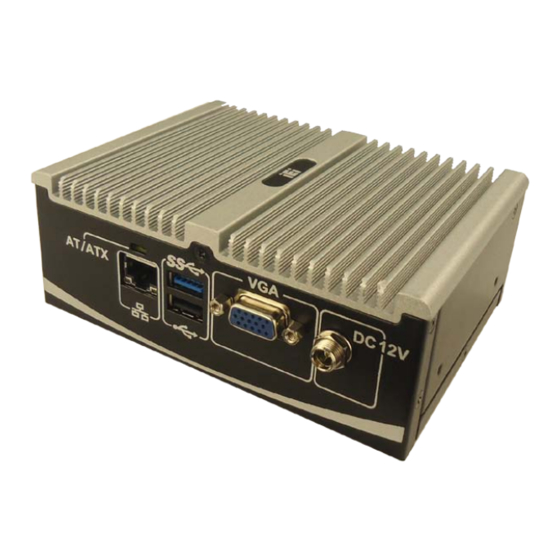
IEI Technology uIBX-230-BT Series User Manual (96 pages)
Fanles s Embedded Sys tem with Intel Celeron N2930 1.83 GHz, VGA , GbE, One USB 3.0, Three USB 2.0, One COM and RoHS Compliant
Brand:
IEI Technology
| Category:
Industrial PC
| Size: 1 MB
Table of Contents
Table of Contents
4
Introduction
10
Figure 1-1: Uibx-230-BT
11
Figure 1-3: Uibx-230-BT Rear Panel
14
Figure 1-2: Uibx-230-BT Front Panel
14
Dimensions
15
Model Variations
11
Overview
11
Table 1-1: Model Variations
11
Table 1-2: Technical Specifications
13
Rear Panel
14
Features
12
Technical Specifications
12
Front Panel
13
Figure 1-4: Physical Dimensions (MM)
15
2 Unpacking
16
Anti - Static Precautions
17
Unpacking Precautions
17
Packing List
18
Table 2-1: Package List Contents
18
3 Installation
19
Hard Disk Drive (Hdd) Installation
20
Installation and Configuration Steps
20
Installation Precautions
20
Figure 3-2: HDD Bracket
21
Figure 3-4: HDD Retention Screws
23
Figure 3-5: AT/ATX Switch Location
23
Figure 3-6: Reset Button Location
25
Figure 3-7: Power Button Location
25
External Peripheral Interface Connectors
26
Figure 3-8: Mounting Bracket
26
Audio Connection
27
Figure 3-9: Audio Connector
27
Figure 3-10: LAN Connection
28
LAN Connection
28
RS-232Serial Port Connection
28
Figure 3-11: DB-9 Serial Port Connector
29
USB Device Connection
29
VGA Monitor Connection
30
AT Power Mode
24
ATX Power Mode
24
Reset the System
24
Powering O N the System
25
Mount the System
25
Figure 3-1: Retention Screws Removal
21
Figure 3-3: HDD Retention Screws
22
At/Atx Mode Selection
23
Figure 3-12: USB Device Connection
30
Figure 3-13: VGA Connector
31
4 System Motherboard
32
Figure 4-1: System Motherboard
33
Table 4-1: Peripheral Interface Connectors
34
Table 4-2: AT/ATX Mode Select Switch Settings
35
Battery Connector
36
Audio Connector
35
Internal Peripheral Connectors
33
Overview
33
Layout
33
AT/ATX Mode Select Switch
34
Figure 4-2: AT/ATX Mode Select Switch Location
35
Figure 4-3: Audio Connector Location
36
Table 4-4: Battery Connector Pinouts
37
Buzzer Connector
38
Clear CMOS Button
38
Table 4-3: Audio Connector Pinouts
36
BIOS FW Connector
37
Figure 4-5: BIOS FW Connector Location
37
Figure 4-4: Battery Connector Location
37
Figure 4-6: Buzzer Connector Location
38
Table 4-5: BIOS FW Connector Pinouts
38
Table 4-6: Buzzer Connector Pinouts
38
Figure 4-7: Clear CMOS Button Location
39
Table 4-8: CPU Fan Connector Pinouts
40
Display Port Connector
41
Figure 4-20: LAN Connector
50
Table 4-18: Rear Panel Connectors
50
Table 4-19: LAN Pinouts
50
Table 4-20: Connector Leds
50
Power Connector
51
Table 4-21: Power Connector Pinouts
51
Table 4-22: USB 2.0 & USB 3.0 Port Pinouts
51
USB Connectors
51
Figure 4-21: VGA Connector
52
Table 4-23: VGA Connector Pinouts
52
VGA Connector
52
Bios
53
Introduction
54
Starting Setup
54
Using Setup
54
BIOS Menu Bar
55
Getting Help
55
Unable to Reboot after Configuration Changes
55
Table 4-7: Clear CMOS Button Settings
39
DDR3L SO-DIMM Slot
40
Figure 4-8: CPU Fan Connector Location
40
Figure 4-10: Display Port Connector Location
41
Figure 4-9: DDR3L SO-DIMM Slot Location
41
Figure 4-11: EC FW Connector Location
42
Table 4-9: Display Port Connector Pinouts
42
Figure 4-12: Front Panel Connector Location
43
Front Panel Connector
43
LAN LED Connector
43
Table 4-10: EC FW Connector Pinouts
43
Table 4-11: Front Panel Connector Pinouts
43
Figure 4-13: LAN LED Connector Location
44
Power Button Connector
44
Table 4-12: LAN LED Connector Pinouts
44
Figure 4-14: Power Button Connector Location
45
Reset Button Connector
45
Table 4-13: Power Button Connector Pinouts
45
Figure 4-15: Reset Button Connector Location
46
RS-232 Serial Port Connector
46
Table 4-14: Reset Button Connector Pinouts
46
Figure 4-16: RS-232 Serial Port Connector Location
47
SATA 3Gb/S Drive Connector
47
Table 4-15: RS-232 Serial Port Connector Pinouts
47
Figure 4-17: SATA 3Gb/S Drive Connector Location
48
Figure 4-18: SATA Power Connector Location
48
SATA Power Connector
48
Table 4-16: SATA Power Connector Pinouts
48
External Interface Panel Connectors
49
Figure 4-19: USB Connector Location
49
Table 4-17: USB Connector Pinouts
49
USB Connector
49
LAN Connector
50
EC FW Connector
42
CPU Fan Connector
39
5 Bios
54
Table 5-1: BIOS Navigation Keys
55
Main
56
Advanced
57
ACPI Settings
58
IT8528 Super IO Configuration
59
Serial Port 1 Configuration
59
Hardware Monitor
60
Smart Fan Mode Configuration
61
RTC Wake Settings
64
Serial Port Console Redirection
65
Console Redirection Settings
66
CPU Configuration
69
IDE Configuration
70
USB Configuration
71
Chipset
72
North Bridge Configuration
73
Intel IGD Configuration
73
Southbridge Configuration
75
Security
77
Boot
78
Exit
80
A Safety Precautions
82
Safety Precautions
83
General Safety Precautions
83
Anti-Static Precautions
83
A.1 S Afety P Recautions
83
Product Disposal
84
Maintenance and Cleaning Precautions
85
Maintenance and Cleaning
85
Cleaning Tools
85
A.2 M Aintenance and C Leaning P Recautions
85
B Bios Menu Options
87
C Watchdog Timer
90
D Hazardous Materials Disclosure
93
Hazardous Materials Disclosure Table for Ipb Products Certified as R Ohs Compliant under 2002/95/Ec Without Mercury
94
D.1 H Azardous M Aterials D Isclosure T Able for Ipb P Roducts C Ertified as R O Hs C Ompliant U Nder 2002/95/Ec W Ithout M Ercury
94
Advertisement
Advertisement
Related Products
IEI Technology uIBX-200-VX800
IEI Technology uIBX-210-CV-N2600 Series
IEI Technology uIBX-260-EHL Series
IEI Technology UPC-12A/GM45
IEI Technology UPC-V312-D525
IEI Technology UPC-V315-QM77
IEI Technology uSmart3400
IEI Technology UPC-F12C-ULT3
IEI Technology UPC-F12M1-RPLP
IEI Technology AFL3-W15C-ADLP
IEI Technology Categories
Motherboard
Touch Panel
Computer Hardware
Single board computers
Desktop
More IEI Technology Manuals
Login
Sign In
OR
Sign in with Facebook
Sign in with Google
Upload manual
Upload from disk
Upload from URL