Table of Contents
Advertisement
Quick Links
Advertisement
Table of Contents

Related Manuals for FLIR 793950385753


Summary of Contents for FLIR 793950385753
- Page 1 1.888.610.7664 www.calcert.com sales@calcert.com...
-
Page 2: Table Of Contents
7.1 General Settings Navigation 7.1.1 Diode SMART/CLASSIC 7.1.2 APO (Auto Power OFF) 7.1.3 Datalogger Sample Rate 7.1.4 Real-time Clock 7.1.5 Battery Selection 7.1.6 Bluetooth® ON/OFF 7.1.7 Button-press tone ON/OFF 7.1.8 Language selection FLIR CM275 USER MANUAL Document Identifier: CM275-en-US_AC 1.888.610.7664 www.calcert.com sales@calcert.com... - Page 3 9.16 Capacitance Measurements 10. BLUETOOTH® COMMUNICATION 11. APPENDICES 11.1 Emissivity Factors for Common Materials 11.2 Non-Uniformity Correction 11.3 Infrared Energy and Thermal Imaging Overview 12. MAINTENANCE 12.1 Cleaning and Storage FLIR CM275 USER MANUAL Document Identifier: CM275-en-US_AC 1.888.610.7664 www.calcert.com sales@calcert.com...
- Page 4 12.2 Battery Replacement 12.3 Disposal of Electronic Waste 13. SPECIFICATIONS 13.1 General specifications 13.2 Thermal Imaging Specifications 13.3 Electrical Specifications 14. TECHNICAL SUPPORT 15. WARRANTY FLIR CM275 USER MANUAL Document Identifier: CM275-en-US_AC 1.888.610.7664 www.calcert.com sales@calcert.com...
-
Page 5: Advisories
1. Advisories 1.1 Copyright © 2020, FLIR Systems, Inc. All rights reserved worldwide. No parts of the software including source code may be reproduced, transmitted, transcribed or translated into any language or computer language in any form or by any means, electronic, magnetic, optical, manual or otherwise, without the prior written permission of FLIR Systems. -
Page 6: Safety
Before operating the device, you must read, understand, and follow all instructions, dangers, warnings, cautions, and notes. FLIR Systems reserves the right to discontinue models, parts or accessories, and other items, or to change specifications at any time without prior notice. - Page 7 This symbol, adjacent to a terminal, indicates that, under normal use, hazardous voltages may be present. Double insulation. UL listing is not an indication or a verification of the accuracy of the meter FLIR CM275 USER MANUAL Document Identifier: CM275-en-US_AC 1.888.610.7664 www.calcert.com...
-
Page 8: Introduction
3. Introduction Thank you for selecting the FLIR CM275 Imaging Clamp meter with IGM (Infrared Guided Measurement) and Bluetooth®. The CM275 is a True RMS 600A AC/DC clamp meter with a radiometric Lepton Thermal Imaging system, integrated VFD Mode, Inrush Current capture, , Bluetooth®... -
Page 9: Meter Description
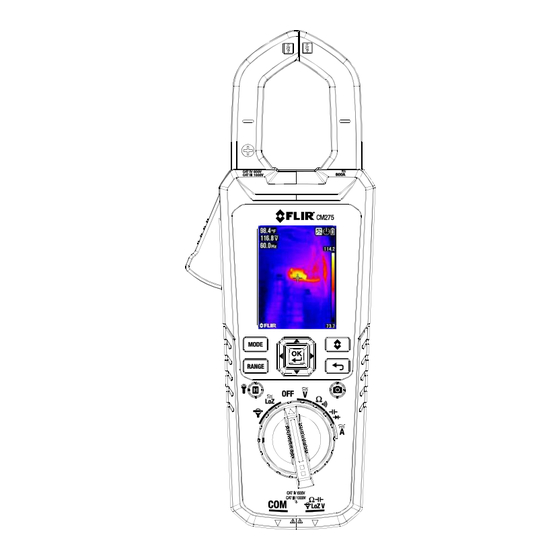
(short press) Color TFT Display Clamp jaw Work lights Laser pointer lens Thermal Imaging lens Tripod mount Battery compartment (micro USB port) Battery compartment lock/unlock Fig. 4-2 Rear View FLIR CM275 USER MANUAL Document Identifier: CM275-en-US_AC 1.888.610.7664 www.calcert.com sales@calcert.com... -
Page 10: Function Switch Positions
1.888.610.7664 www.calcert.com sales@calcert.com... -
Page 11: Mode Button Sequence Of Operations
1.888.610.7664 www.calcert.com sales@calcert.com... -
Page 12: Other Display Icons
Current (Amperes) Farad (for Capacitance) Hertz (Frequency) (kilo) (milli) (micro) Out of Range warning Bar Graph Bar Graph overload indicator Meter is measuring voltage > 30 V (AC or DC) FLIR CM275 USER MANUAL Document Identifier: CM275-en-US_AC 1.888.610.7664 www.calcert.com sales@calcert.com... -
Page 13: Meter Power
The user must enter the battery type (Lithium or Alkaline) in the General Settings menu before use. This allows the meter to display battery status as accurately as possible. Refer to Section 7.1.5, Battery Selection. FLIR CM275 USER MANUAL Document Identifier: CM275-en-US_AC 1.888.610.7664 www.calcert.com sales@calcert.com... -
Page 14: Menu System
Laser pointer ON/OFF, and Cross hairs ON/OFF. Refer to Section 8.3, Thermal Settings Menu (Color Palette, Emissivity, Temperature Units, Laser Pointer, and Crosshairs) for detailed information. Fig. 6-2 Thermal Settings Menu FLIR CM275 USER MANUAL Document Identifier: CM275-en-US_AC 1.888.610.7664 www.calcert.com sales@calcert.com... -
Page 15: Gallery Mode
6.2.5 General Settings Menu Press OK to open the main menu. Press OK at the General Settings icon to access the options. See next section for detailed information on the General Settings mode FLIR CM275 USER MANUAL Document Identifier: CM275-en-US_AC 1.888.610.7664 www.calcert.com sales@calcert.com... -
Page 16: General Settings
1.888.610.7664 www.calcert.com sales@calcert.com... -
Page 17: Battery Selection
Press OK to delete all saved images. The meter will ask for confirmation 7.1.11 View HELP Screen Press OK to view FLIR support contact information 7.1.12 Viewing meter component information Press OK to view meter component firmware version information and Laser data: Meter firmware version Lepton®... - Page 18 1.888.610.7664 www.calcert.com sales@calcert.com...
- Page 19 30 times smaller than the distance from meter to spot See Fig. 8-2. ield of View) is 44 degrees (vertical) and 57 degrees (horizontal) see Fig. 8-3 (a) and (b). Fig. 8-2 Distance-to-Spot ratio 30:1 FLIR CM275 USER MANUAL Document Identifier: CM275-en-US_AC 1.888.610.7664 www.calcert.com sales@calcert.com...
- Page 20 1.888.610.7664 www.calcert.com sales@calcert.com...
- Page 21 IR temperature measurement instead of dashes) before radiometric data can be captured. To view radiometric data within captured thermal images, copy the images to a PC and view using FLIR Tools. To view stored images: 1. Press OK to open the Main Menu 2.
- Page 22 4. The blue dot next to the icon and the VFD display icon will appear 5. De-select the VFD mode by pressing OK again. The blue dot and VFD display icon will switch OFF when de-selected FLIR CM275 USER MANUAL Document Identifier: CM275-en-US_AC 1.888.610.7664 www.calcert.com...
- Page 23 3. Use the up arrow to move the cursor up to the log area of the display (the lower area is for saved images). Scroll left/right to a set and press OK to open it. The list of recorded measurements for the set will appear. FLIR CM275 USER MANUAL Document Identifier: CM275-en-US_AC 1.888.610.7664 www.calcert.com...
- Page 24 3. To delete ALL datalog sets at once, see Section 7.1.9, Delete All Datalog Readings. To transmit a datalog set via Bluetooth®: 1. Transmit data logs to a remote device running the FLIR Tools software suite. Refer to Section 10, Bluetooth® Communication for more information.
- Page 25 7. To see the Frequency measurement for an AC Current measurement use the button to step to the Hz display. 8. For VFD mode operation refer to Section 9.4, VFD Mode. 9. For MAX-MIN operation, refer to Section 9.5, MAX-MIN Mode. FLIR CM275 USER MANUAL Document Identifier: CM275-en-US_AC 1.888.610.7664 www.calcert.com sales@calcert.com...
- Page 26 1.888.610.7664 www.calcert.com sales@calcert.com...
- Page 27 6. Turn on the power to the circuit under test 7. When it reaches the threshold, the meter will display the RMS reading for the 100ms integration time. Fig. 9-3 Inrush Current FLIR CM275 USER MANUAL Document Identifier: CM275-en-US_AC 1.888.610.7664 www.calcert.com...
- Page 28 Hz reading appears. For VFD mode operation refer to Section 9.4, VFD Mode. For MAX-MIN operation, refer to Section 9.5, MAX-MIN Mode. Fig. 9-4 Voltage and Frequency Measurements FLIR CM275 USER MANUAL Document Identifier: CM275-en-US_AC 1.888.610.7664 www.calcert.com sales@calcert.com...
- Page 29 1.888.610.7664 www.calcert.com sales@calcert.com...
- Page 30 1.888.610.7664 www.calcert.com sales@calcert.com...
- Page 31 1.888.610.7664 www.calcert.com sales@calcert.com...
- Page 32 1.888.610.7664 www.calcert.com sales@calcert.com...
- Page 33 Download the FLIR Tools software suite at the link below: http://www1.flir.com/l/5392/2011-06-08/IUUE 1. Any Bluetooth® BLE device running FLIR Tools can find and connect to the CM275. 2. When successful communication between the meter and a remote device or FLIR camera is established, the Bluetooth® icon appears on the meter display.
- Page 34 ±2 C temperature change. 1. Definition from the imminent international adoption of DIN 54190-3 (Non-destructive testing Thermographic testing Part 3: Terms and definitions). FLIR CM275 USER MANUAL Document Identifier: CM275-en-US_AC 1.888.610.7664 www.calcert.com...
- Page 35 The infrared imager converts this energy into an image that we can interpret. The FLIR Infrared Training center offers training (including online training) and certification in all aspects of thermography: http://www.infraredtraining.com/. FLIR CM275 USER MANUAL Document Identifier: CM275-en-US_AC 1.888.610.7664...
- Page 36 As with most electronic products, this equipment must be disposed of in an environmentally friendly way, and in accordance with existing regulations for electronic waste. Please contact your FLIR Systems representative for more details. FLIR CM275 USER MANUAL Document Identifier: CM275-en-US_AC 1.888.610.7664...
- Page 37 3 × 1.5 V AA or TA04 rechargeable battery Approximate battery life for thermal imager: hours: Energizer L91 Lithium (Li/FeS hours: Optional Rechargeable Battery: Li-Polymer; FLIR PN: TA04-KIT Calibration: 1-year calibration cycle Operating temperature: 32 to 86°F (0 to 30°C) ( 80% RH) 86 to 104°F (30 to 40°C) ( 75% RH)
- Page 38 ±5.4°F (3°C) or ± 3% of reading; whichever is greater Distance to Spot (D:S) ratio 30:1 Temperature Scanning Continuous Emissivity 4 presets plus a custom setting (0.10 to 0.99) Targeting Displayed Cross hairs pinpoint center of measurement spot FLIR CM275 USER MANUAL Document Identifier: CM275-en-US_AC 1.888.610.7664 www.calcert.com sales@calcert.com...
- Page 39 For a crest factor of 1.0 2.0, add 3.0% to the accuracy. For a crest factor of 2.0 2.5, add 5.0% to the accuracy. For a crest factor of 2.5 3.0, add 7.0% to the accuracy. FLIR CM275 USER MANUAL Document Identifier: CM275-en-US_AC 1.888.610.7664 www.calcert.com...
- Page 40 > 600V (rms) at 1000V range for 10Hz ~ 1kHz Hz function at ACV rotary switch: > 6V (rms) for 10Hz ~ 10kHz > 30V (rms) for 10kHz ~ 60kHz FLIR CM275 USER MANUAL Document Identifier: CM275-en-US_AC 1.888.610.7664 www.calcert.com sales@calcert.com...
- Page 41 Maximum test current: Approx. 0.1 mA. : Approx. 1.8 V. Maximum open circuit voltage for diode: Approx. 1.8 V. Continuity threshold: > Continuity indicator: 2.7 kHz tone buzzer. Continuity response time: <100 ms. FLIR CM275 USER MANUAL Document Identifier: CM275-en-US_AC 1.888.610.7664 www.calcert.com sales@calcert.com...
- Page 42 30.00 A Flex (ACA) 300.0 A ±(1% + 5 dgt) 45 ~ 400Hz 3000 A Additional accuracy for the Flex function is listed in the FLIR clamp adaptor User Manuals (Models TA72_TA74). Table 13.8 Flex Clamp Adaptor Function (Frequency) Function Range Accuracy 600.0 Hz...
- Page 43 14. Technical Support Technical Support Website https://support.flir.com FLIR CM275 USER MANUAL Document Identifier: CM275-en-US_AC 1.888.610.7664 www.calcert.com sales@calcert.com...
- Page 44 15. Warranty 15.1 FLIR Limited 10-year Warranty -Year Warranty. Visit https://support.flir.com/prodreg to read the Limited 10-Year Warranty document. FLIR CM275 USER MANUAL Document Identifier: CM275-en-US_AC 1.888.610.7664 www.calcert.com sales@calcert.com...
Need help?
Do you have a question about the 793950385753 and is the answer not in the manual?
Questions and answers