Table of Contents
Advertisement
Quick Links
Advertisement
Table of Contents

Related Manuals for THORLABS PM200


Summary of Contents for THORLABS PM200
- Page 1 Optical Power and Energy Meter PM200 Operation Manual 2012...
- Page 2 Version: 1.0.1 Date: 08.02.2012 Copyright © 2012 Thorlabs...
-
Page 3: Table Of Contents
Contents Foreword 1 General Information 1.1 Safety 1.2 Ordering Codes and Accessories 1.3 Requirements 1.3.1 Hardware Requirements 1.3.2 Software Requirements 1.3.3 Interface Requirements 2 Installation 2.1 Parts List 2.2 Operating Elements 2.3 Getting Started 3 Operating Instruction 3.1 Attenuation Correction 3.2 Wavelength Correction 3.3 Bandwidth 3.4 Range Control... - Page 4 5 Maintenance and Service 5.1 Troubleshooting 6 Appendix 6.1 Sensor Connector Pinning 6.2 Technical Data 6.3 Certifications and Compliances 6.4 Warranty 6.5 Copyright 6.6 Thorlabs 'End of Life' Policy (WEEE) 6.7 Listings 6.7.1 List of Acronyms 6.7.2 Thorlabs Worldwide Contacts...
-
Page 5: Foreword
Paragraphs preceeded by this symbol explain hazards that could damage the instrument and the connected equipment or may cause loss of data. NOTE This manual also contains "NOTES" and "HINTS" written in this form. Please read these advices carefully! © 2012 Thorlabs... -
Page 6: General Information
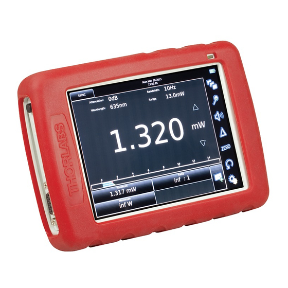
PM200 General Information The PM200 Handheld Optical Power and Energy Meter is designed to measure the optical power of laser light or other monochromatic or near monochromatic light sources and the energy of pulsed light sources. The space-saving, battery powered design and compatibility to all Thorlabs “C- Series”... -
Page 7: Ordering Codes And Accessories
350 - 1100 100p - 5m S151C Fiber Head 3.6 x 3.6 400 - 1100 1n - 20m S154C Fiber Head InGaAs 700 - 1700 100p - 5m S155C Fiber Head InGaAs 700 - 1700 1n – 20m © 2012 Thorlabs... - Page 8 185 - 25000 500µ - 3 ceramic coating ES245C Pyroelectric Sensor with 185 - 25000 1m -15 ceramic coating Please visit our homepage http://www.thorlabs.com for various accessories like fiber adapters, posts and post holders, data sheets and further information. © 2012 Thorlabs...
-
Page 9: Requirements
USB cable according the USB 2.0 specification 1.3.2 Software Requirements Operating System: Windows ® XP (32-bit) SP3 Windows ® Vista (32-bit, 64-bit) Windows ® 7 (32-bit, 64-bit) VISA runtime (version 5.0.3 or higher) 1.3.3 Interface Requirements A free USB2.0 port is required. © 2012 Thorlabs... -
Page 10: Installation
Inspect the shipping container for damage. If the shipping container seems to be damaged, keep it until you have inspected the contents and you have inspected the PM200 mechanically and electrically. Verify that you have received the following items within the package: 1. -
Page 11: Operating Elements
1. LED indicators for „Standby“ mode and „Charging“ 2. Touch-pen 3. Touch-screen display 4. Removable protective silicone rubber boot Rear Panel 5. Four position rotatable and two flap position adjustable stand 6. Adaptor for optional fiber inspection camera © 2012 Thorlabs... -
Page 12: Getting Started
During the charging process the right LED indicator lights up, even when the unit is turned off. Connect a suitable Thorlabs “C-series” power or energy sensor. The sensors have a self-fixing mechanism. To plug or unplug a sensor slightly press from both sides on the pins in the connector housing. -
Page 13: Operating Instruction
These can easily identified against older versions of Thorlabs power or energy sensors by their red connector housing. The console will not recognize sensors from the ‘A’ and ‘B’ series. Please contact Thorlabs for upgrading of old sensors with ‘C-Series’ connectors. -
Page 14: Attenuation Correction
'eff. curve', the superposition of the sensor's response curve and the filter curve can be seen. Wavelength Correction The PM200 allows the creating and administering of a nearly unlimited number of user wavelengths and spectral curves of light sources that will be used for calculating the spectrally corrected power or energy value. - Page 15 Load spectral curve Quit editor A specialty of the PM200 is the possibility to load spectral curves of broadband light sources. These files must be in comma separated format (.csv), can be loaded from the USB drive and will be stored in the user space of the local drive.
-
Page 16: Bandwidth
For power measurements an auto-ranging function is available that can be activated by clicking on the Range label (toggle function) or via the list box, which appears when clicking on measurement range value. © 2012 Thorlabs... -
Page 17: Measurement Views
From this panel, also graph and statistics measurement panels can be selected. Additionally, the File Manager and the Calculator can be started. 3.5.1 Numeric View The upper part of the display important measurement settings are displayed. © 2012 Thorlabs... -
Page 18: Subpanels
Frequency The PM200 can measure and display frequencies of pulsed, modulated or chopped light sources up to 100kHz. The maximum measurable frequency is depending on the sensor type and instrument settings. The measured frequency is displayed in a subpanel. - Page 19 The calculation is based on the beam parameters, entered in Measurement Settings panel ( and in the next panel Beam shapes can be selected from a drop-down menu: To change the beam dimension, click into the numeric field - an editor comes up: © 2012 Thorlabs...
- Page 20 These values will update permanently. The "Reset Min / Max" button will reset the displays to zero and restart the measurement sampling. The ratio value will show "nan" ("No A Number") when a negative reading occurs. © 2012 Thorlabs...
-
Page 21: Needle View
For recording, visualizing and analyzing the measurement data in Watts or Joules over time, the PM200 features a scope view and a statistics analysis with a histogram view. During the record, the data will be stored to an internal temporary file. - Page 22 During the record it is possible to quickly swap between the Graph and the Statistic View as in the following screen shots. Graph View Statictics View By clicking to the histogram area, the histogram will be displayed in the entire © 2012 Thorlabs...
-
Page 23: Calculator
- the calculator derives beam parameters essential for sensor choice and outputs a list of suitable sensor heads. Below are two examples - for CW and pulsed lasers. Beam Parameter Calculator for CW Lasers Beam Parameter Calculator for Pulsed Lasers © 2012 Thorlabs... -
Page 24: File Manager
All files can be copied to and from the USB drive. To remove a custom folder, the folder must be selected (opened). The rename, copy and paste function is only available for files, not for directories. Note Above default folders cannot be deleted nor renamed. File manager © 2012 Thorlabs... -
Page 25: Zoom
Watts or dBm. The basic units (A, V) will still measure the absolute values without zero correction. The detected zero value may influence the wavelength corrected calculated full scale power range values in the lower © 2012 Thorlabs... -
Page 26: Min/Max Marker Reset
Thermal Sensors: accelerator (speed-up circuitry) settings Also, in this panel the following settings can be made: Beam characteristic parameters for calculating the power or energy density Configuration of the PM200 for customer built sensors Long-term logging control © 2012 Thorlabs... -
Page 27: Settings
System Info: Shows system relevant data and triggers the software update via USB stick. Sensor Info: Shows sensor relevant data and the spectral response curve To return to the measurement view, press the arrow button in the operating © 2012 Thorlabs... -
Page 28: Analog Output
3.14 Charging the Battery The PM200 is powered by a 2 cell LiPo+ battery that needs to be recharged intermittently by plugging the AC adapter. To fully charge the battery it takes approximately 4 hours. A built in charging circuit automatically regulates and terminates the charging. -
Page 29: Sensor Dependent Functions
Refer to the sensor data sheet and pay attention to the optical damage threshold! Exceeding these values will permanently destroy the sensor! For the measurement of power levels from nano-watts up to 20 W Thorlabs offers photodiode sensors that show big advantages in sensitivity, stability and drift compared to thermal sensors. - Page 30 7 and pin 3) must be connected. In order to measure the power, a response curve of the used photo diode must be loaded. If no responsivity curve is available, the PM200 uses a default responsivity of 1A/W, and only photo current measurement is possible.
-
Page 31: Thermal Sensors
1-3 seconds by ‘predicting’ the final power value. The PM200 automatically uses the right adjustment of the electronics to the time constant of the recognized thermal sensor. Nevertheless this circuitry has the disadvantage of inducing some noise to the measurement value. - Page 32 Select from the 'LOCAL > response-curves' folder the desired file and hit the select button. The responsivity curve now will be displayed and used for calculations. If no responsivity curve is available, the PM200 uses a default responsivity of 1V/ W, and only voltage measurement is possible. © 2012 Thorlabs...
-
Page 33: Pyroelectric Sensors
The trigger level can be adjusted between 0% and 99% of each selected energy range. Only pulses that are higher than the adjusted trigger level are recognized by the PM200. The trigger level should be set between the noise level and the expected pulse height. - Page 34 Custom Pyroelectric Sensors Custom pyroelectric detectors can be used for energy measurements with the PM200. Therefore to the sensor input (see Sensor Connector Pinning ) the pyroelectric sensor ('+' to pin 5) and an interlock (1..10 k between pin 7 and pin 3) must be connected.
- Page 35 3 Operating Instruction The responsivity curve now will be displayed and used for calculations. If no responsivity curve is available, the PM200 uses a default responsivity of 1V/ J, and only peak voltage measurement is possible. © 2012 Thorlabs...
-
Page 36: Application Note
- The housing of power sensors are connected to the digital ground of the meter and should be linked to earth ground (e.g. via a post); energy sensors should be mounted isolated, because the housing is connected to the console's © 2012 Thorlabs... - Page 37 - The temperature should be stable over the time of the measurement. Power Measurement of Pulsed Signals The PM200 will read the average value of a pulsed signal when the following conditions apply: For a thermal sensor pulse length, repetition rate and peak power is uncritical as long as the peak power is lower than the damage threshold of the sensor.
- Page 38 PM200 Note PM200 allows to load a spectral curve of a light source, having a broad line width. If select such a spectral curve instead of a center wavelength from the 'Wavelength' drop down menu, the PM200 will calculate the optical power correctly.
- Page 39 The maximum ratings are given in the sensor spec sheet. The PM200 can display the actual power or energy density for a known beam diameter. For high power or high energy beams a good efficiency can be reached to chose a detector that has a active area diameter about 20% - 30% larger than the beam diameter.
- Page 40 The display unit has an input resistor of 1MΩ (like the typical input resistor of an Oscilloscope). – Pulse Length: Thorlabs energy sensors detect and measure pulses from sub nano-seconds duration up to approximately 2 ms. Generally, the pyroelectric effect allows just the measurement of a temperature change caused by radiation pulses or modulated radiation.
-
Page 41: Computer Interface
USB port of your PC. When connecting the PM200 first time, a new hardware will be found. For proper installing the PM200 it requires a NI-VISA runtime version on the PC (available on the National Instruments website www.ni.com) or from the data carrier that comes with the... - Page 42 PM200 The identification string contains the following items: USB0 USB Port number 0x1313 Thorlabs Vendor ID 0x80B0 Product ID = PM200 P3000116 Instrument serial number INSTR Measurement instrument device Front Panel Description of the Front Panel Elements: Header This indicator shows the device setup:...
- Page 43 A/W or V/W. The currently used parameter is indicated in the button label. Shortcut: [Shift + F2] Measurement configuration button Depending on the connected sensor the following parameters can be set in the dialog box: © 2012 Thorlabs...
- Page 44 - clear power / energy statistics - clear log screen Shortcut: [Shift + F7] Quit button - stops the PM200 application - to restart press the white arrow in the tool bar Shortcut: [Shift + F8] Instrument Setup Save / Recall...
-
Page 45: Pm200 Software Update
4 Computer Interface PM200 Software Update Download the PM200 Update Package from Thorlabs' web site and copy it to the root directory of a USB flash drive. Connect Open 'Measurement Settings' panel and call 'System Info' - the following screen appears: Click to 'update software', make sure the power supply is connected. -
Page 46: Using The Instrument Drivers
To successfully complete the install of the PM200 USB driver you must have Administrator privileges on the PC which you are performing the install. Prior to connecting the PM200 with a PC, please check if NI-VISA is installed on the PC, otherwise install NI-VISA that is available for free from the National Instruments website www.ni.com or from the data carrier that came with the... - Page 47 The command syntax shows most commands (and some parameters) as a mixture of upper- and lower-case letters. The upper-case letters indicate the abbreviated spelling for the command. For shorter program lines, send the abbreviated form. For better program readability, send the long form. © 2012 Thorlabs...
- Page 48 "CORR:BEAM 1;:AVER 300" Using the MIN and MAX Parameters You can substitute in place of a parameter for many MINimum MAXimum commands. For example, consider the following command: CURRent[:DC]:RANGe {MINimum|MAXimum|<numeric_value>[A]} © 2012 Thorlabs...
- Page 49 Use a semicolon (;) to separate multiple commands as shown below: "*RST; *CLS; *ESE 32; *OPC?" SCPI Parameter Types The SCPI language defines several different data formats to be used in program messages and response messages. © 2012 Thorlabs...
- Page 50 You can include the quote delimiter as part of the string by typing it twice without any characters in between. The following command uses a string parameter: DIAG:CALString <quoted string> © 2012 Thorlabs...
-
Page 51: Ieee488.2 Common Commands
Service request enable query Reads the Service Request Enable Register *STB? Status byte query Reads the Status Byte Register Performs the unit’s self-test and returns the *TST? Self-test query result. *WAI Wait-to-continue command Wait until all previous commands are executed © 2012 Thorlabs... -
Page 52: Command Reference
PM200 4.4.2.2 Command Reference *IDN? – identification query - read identification code The identification code includes the manufacturer, model code, serial number, and firmware revision levels and is sent in the following format: THORLABS, MMM,SSS,X.X.X Where: MMMis the model code SSS is the serial number X.X.X... -
Page 53: Pm200 Specific Scpi Command Reference
4 Computer Interface 4.4.2.3 PM200 specific SCPI Command Reference also SCPI Specification, Version 1999.0, May, 1999, http:// www.scpiconsortium.org . All commands with a ’SCPI’ checkmark are described in the SCPI specification. All described commands work also with the PM100D, PM100A and PM100USB instruments (with some limitations due to the hardware capabilities). - Page 54 Read the positive transition filter :PTRansition? :NTRansition <value> Program the negative transition filter :NTRansition? Read the negative transition filter Program the enable register :ENABle <value> :ENABle? Read the enable register :PRESet Return status registers to default states. © 2012 Thorlabs...
- Page 55 Queries the zero value BEAMdiameter {MINimum| Sets the beam diameter in mm MAXimum|DEFault| <numeric_value>[mm]} BEAMdiameter? [{MINimum| Queries the beam diameter MAXimum|DEFault}] WAVelength {MINimum| Sets the operation wavelength in nm MAXimum| <numeric_value>[nm]} WAVelength? [{MINimum| Queries the operation wavelength MAXimum}] © 2012 Thorlabs...
- Page 56 Switches to delta mode Queries the delta mode state STATe? ENERgy RANGe [:UPPer] {MINmum|MAXimum| Sets the energy range in J <numeric_valuje>[J]} [:UPPer]? [{MINimum| Queries the energy range MAXimum}] REFerence {MINimum| Sets a delta reference value in J MAXimum|DEFault| <numeric_value>[J]} © 2012 Thorlabs...
- Page 57 Queries the delta reference value MAXimum|DEFault}] STATe {OFF|0|ON|1} Switches to delta mode Queries the delta mode state STATe? PEAKdetector [:THReshold] {MINimum| Sets the trigger level in % for the energy mode MAXimum|DEFault| <numeric_value> [:THReshold]? [{MINimum| Queries the trigger level setting MAXimum|DEFault} © 2012 Thorlabs...
- Page 58 Queries thermopile accelerator auto mode :TAU {MINimum| Sets thermopile time constant 0-63% in s MAXimum|DEFault| <numeric_value>[s]} :TAU? [{MINimum| Queries the thermopile time constant in s MAXimum|DEFault}] :ADAPter Sets default sensor adapter type [:TYPE] {PHOTodiode| THERmal|PYRo} [:TYPE]? Queries default sensor adapter type © 2012 Thorlabs...
-
Page 59: Measurement Commands
:RESistance Performs a sensor presence resistance measurement :TEMPerature Performs a sensor temperature measurement FETCh? Read last measurement data (SCPI Vol.2 §3.2) READ? Start new measurement and read data (SCPI Vol.2 §3.3) CONFigure? Query the current measurement configuration. © 2012 Thorlabs... -
Page 60: Simple Labview Example Using Scpi Commands
PM200 4.4.3 Simple LabVIEW Example using SCPI commands PM100D Simple Example.vi This VI shows how to communicate with a PM200 optical power/energy meter with SCPI commands. The following steps are demonstrated within this application: - Initializing the instrument - Getting system info... - Page 61 Sets a timeout value in ms that allows the instrument to sample. The timeout must be longer than it takes to perform a new measurement. This has especially to be considered when performing single shot energy measurements. © 2012 Thorlabs...
- Page 62 - performing identification query - configuring the operation register to '512'; flag gets to HI when a new measurement value is ready to fetch - clear operation register PM100D_Write.vi Writes a SCPI command to the connected instrument © 2012 Thorlabs...
- Page 63 - Clear operation register with STAT:OPER? - INITiate measurement PM100D_SYST-ERR.vi This VI lists all errors coming from the instrument with the command SYST:ERR? 'no error' is suppressed PM100D_Close.vi Closes the VISA session Sets the connected instrument in local mode (default option) © 2012 Thorlabs...
-
Page 64: Maintenance And Service
PM200 Maintenance and Service Protect the PM200 from adverse weather conditions. The PM200 is not water resistant. Attention To avoid damage to the instrument, do not expose it to spray, liquids or solvents The unit does not need a regular maintenance by the user. It does not contain any modules and/or components that could be repaired by the user himself. -
Page 65: Appendix
+5V (max. current 50mA from this pin) DGND (digital ground) n.c. Warning Pin 2 is uniquely used for the EEPROM Digital I/O (memory in Thorlabs sensor heads) and MUST NOT be used. Connecting this pin may cause malfunction of the PM200. © 2012 Thorlabs... -
Page 66: Technical Data
Bandwidth DC - 10 Hz, Dependent on Sensor and Settings Time Constant Correction Range 1 s - 30 s Wavelength Correction Sensor Dependent; nm, (V/W) Beam Area Setting Diameter 1/e² or Rectangular x,y Voltage Input (Pyro Sensors) © 2012 Thorlabs... -
Page 67: Power Management
Interfaces Type USB2.0 Connector (Host) Mini USB, Top Side Connector (Device) USB Type A, Left Side Power Management Battery LiPo 3.7 V 2600 mAh Charger / DC Input 5 V / 2 A Power Connector Center Hole © 2012 Thorlabs... - Page 68 -40 to 70 °C Dimensions (W x H x D) 170 mm x 125 mm x 38 mm Weight 0.57 kg ) non-condensing All technical data are valid at 23 ± 5°C and 45 ± 15% rel. humidity (non condensing) © 2012 Thorlabs...
-
Page 69: Certifications And Compliances
) Compliance demonstrated using high-quality shielded interface cables. ) Emissions, which exceed the levels required by these standards, may occur when this equipment is connected to a test object. ) Minimum Immunity Test requirement. ) Replaces 73/23/EEC, amended by 93/68/EEC. © 2012 Thorlabs... -
Page 70: Warranty
PM200 Warranty Thorlabs warrants material and production of the PM200 for a period of 24 months starting with the date of shipment. During this warranty period Thorlabs will see to defaults by repair or by exchange if these are entitled to warranty. -
Page 71: Copyright
All rights reserved. This manual may not be reproduced, transmitted or translated to another language, either as a whole or in parts, without the prior written permission of Thorlabs GmbH. Status: 2012 Copyright © Thorlabs GmbH. All rights reserved. -
Page 72: Thorlabs 'End Of Life' Policy (Weee)
Waste treatment on your own responsibility If you do not return an “end of life” unit to Thorlabs, you must hand it to a company specialized in waste recovery. Do not dispose of the unit in a litter bin or at a public waste disposal site. -
Page 73: Listings
The following acronyms and abbreviations are used in this manual: Analog-to-Digital Converter Continuous Wave Dezibel DB-9 Standard 9 pin D-SUB connector Direct Currect GPIO General Purpose Input / Output Light Emitting Diode Negative Temperature Coefficient Universal Serial Bus © 2012 Thorlabs... -
Page 74: Thorlabs Worldwide Contacts
PM200 6.7.2 Thorlabs Worldwide Contacts USA, Canada, and South America Thorlabs, Inc. 56 Sparta Avenue Newton, NJ 07860 Tel: 973-579-7227 Fax: 973-300-3600 www.thorlabs.com www.thorlabs.us (West Coast) Email: sales@thorlabs.com Support: techsupport@thorlabs.com Europe UK and Ireland Thorlabs GmbH Thorlabs Ltd. Hans-Böckler-Str. 6...
Need help?
Do you have a question about the PM200 and is the answer not in the manual?
Questions and answers