Table of Contents
Advertisement
Advertisement
Table of Contents

Related Manuals for THORLABS PM100A


Summary of Contents for THORLABS PM100A
- Page 1 Operation Manual Thorlabs Instrumentation Optical Power Meter PM100A 2011...
- Page 2 Version: 17655-D02 REV C Date: 21.04.2011 © Copyright 2011, Thorlabs, Germany...
-
Page 3: Table Of Contents
Side Panel 3.2.3 Rear Panel 3.2.4 Bottom 3.2.5 Display Operating the PM100A 4.1 Connecting a Power Sensor 4.2 Controlling the PM100A 4.2.1 Navigating the Menus 4.2.2 System Settings 4.2.3 Power Measurement 4.2.3.1 Range and Scale Control 4.2.3.2 Wavelength Correction 4.2.3.3 Zeroing 4.2.3.4 Setting an Attenuation / Gain Factor... - Page 4 6.8 Troubleshooting Appendix 7.1 Warranty 7.2 Certifications and compliances 7.3 Technical data 7.4 Pin Assignment of the Sensor Connector 7.5 Thorlabs „End of Life‟ policy (WEEE) 7.5.1 Waste treatment on your own responsibility 7.5.2 Ecological background 7.6 List of figures...
- Page 5 Thorlabs This part of the instruction manual contains every specific information on the PM100A handheld optical power meter. A general description is followed by explanations of how to operate the unit manually. You will also find information about a simple remote control of the unit.
-
Page 6: General Information
1.1 Safety 1 General Information The PM100A Handheld Optical Power Meter is designed to measure the optical power of laser light or other monochromatic or near monochromatic light sources and the energy of pulsed light sources. The space-saving, battery powered design and compatibility to all Thorlabs “C-Type”... -
Page 7: Safety
All statements regarding safety of operation and technical data in this instruction manual will only apply when the unit is operated correctly. The power meter PM100A must not be operated in explosion endan- gered environments! Sensor, photodiode and control inputs and outputs must only be connected with duly shielded connection cables. - Page 8 ▪ Consult the dealer or an experienced radio/T.V. technician for help. Thorlabs GmbH is not responsible for any radio television interfer- ence caused by modifications of this equipment or the substitution or attachment of connecting cables and equipment other than those specified by Thorlabs GmbH.
-
Page 9: Ordering Codes And Accessories
1.2 Ordering Codes and Accessories 1.2 Ordering Codes and Accessories Order Code Description PM100A Handheld Power Meter Console Photodiode Power Sensors: Order Code Type Detector Aperture Wavelength Power S120C Compact Sensor 400 - 1100 50n - 50m S120VC Compact Sensor... -
Page 10: Getting Started
Inspect the shipping container for damage. If the shipping container seems to be damaged, keep it until you have inspected the contents and you have inspected the PM100A mechanically and electrically. Verify that you have received the following items within the hard-case: 1. -
Page 11: Physical Overview
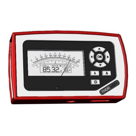
3.2 Physical Overview 3.2 Physical Overview 3.2.1 Front Panel Function Keys: Navigation: Enter/Edit: λ Wavelength: Δ Relative Measure: Backlight Key: Analog Meter Needle Zero Adjust Graphics Display (Switch off unit prior to adjusting!) Figure 1 Physical Overview Front Panel 3.2.2 Side Panel On/Off Switch USB Connector Sensor Connector (DB9 female) -
Page 12: Rear Panel
3.2 Physical Overview 3.2.3 Rear Panel Pull here to lift the support Removable Protective Rubber Boot Figure 3 Rear View 3.2.4 Bottom Mounting Thread 1/4“-20 Figure 4 Physical Overview Bottom View... -
Page 13: Display
3.2 Physical Overview 3.2.5 Display Power Scales Power Range Setting Delta Power Scale Power Scale Setting 4 digit Power Operating Wavelength Menu Items (Soft Buttons) Readout with units Information, Status and Warning Indicators Figure 5 Display Setup Operation Overview Standard Display: Function ... -
Page 14: Operating The Pm100A
2 seconds, and the unit is ready to operate with the new sensor. The PM100A also supports custom detectors, please refer to chapter 4.2.2 for the console measurement settings and chapter 7.4 for the connector pin-out. - Page 15 Sets the unit to the local line frequency 50Hz/60Hz to avoid aliasing effects () Adapter Type Sets the PM100A into the mode to measure photo current or thermal voltage. Please refer to the chapters 4.2.5.1.2, 4.2.5.2.2 and 7.4 for connecting custom sensors. () Page 2: Console Settings ...
-
Page 16: Power Measurement
„HIGH‟. λ 4.2.3.2 Wavelength Correction Most power and energy sensors show a dependent behaviour in their spectral response. For accurate measurements it is important to set the PM100A to the wavelength of the light to measure. λ Pressing the key leads to a wavelength menu with 8+1 individually configurable sensor independent settings. -
Page 17: Zeroing
4.2 Controlling the PM100A To preconfigure or edit a wavelength item, navigate to it and keep the OK key pressed until the last digit gets underlined. Set the desired wavelength with the keys and confirm with OK. When selecting a wavelength that is not applicable for the connected sensor a warning sound will appear and the unit will keep the previous wavelength setting. -
Page 18: Setting An Attenuation / Gain Factor
4.2 Controlling the PM100A After performing a zero adjustment, the detected zero value will be included in all power readings. The detected zero value may influence the wavelength corrected calculated full scale power range values in the lower power ranges. -
Page 19: Relative Power Measurement
Figure 9 Relative Measurement 4.2.4 Display Options The PM100A can toggle between the standard measurement screen and a statistics item and pressing one of the or keys. screen by navigating to the MENU The statistics screen shows the actual, minimum, maximum and average power level. -
Page 20: Sensor Dependent Functions
DB-9 sensor connector and downloaded to the PM100A when plugged to the unit. To perform an accurate measurement it is necessary to enter the operating wavelength of the light to measure so that the PM100A can calculate the laser power from the measured photo current and the right response value from the wavelength calibration table. -
Page 21: Thermal Power Sensors
4.2.5.1.2 Power Measurements with Photodiodes Common photodiodes can be used for power measurements with the PM100A. Therefore the PM100A needs to be set to the „Photodiode‟ default setting in the system menu. MENU \ Adapter Type \ Photo To perform measurements, a photodiode and an interlock must be connected to the sensor input (see chapter 7.4 for the connector pin out);... - Page 22 \ Accelerator On/Off 4.2.5.2.2 Custom Thermal Elements Custom thermal elements can be used for power measurements with the PM100A. Therefore the PM100A needs to be set to the „Thermopile‟ default setting in the system menu: MENU \ Adapter Type \ Thermo To perform measurements, a thermal element and an interlock must be connected to the sensor input (see chapter 7.4 for the connector pin out).
-
Page 23: Analog Output
4.3 Analog Output 4.3 Analog Output The analog output provides on its SMA connector the amplified and buffered photo- diode current or thermal sensor voltage. For photodiode sensors the bandwidth setting influences the output signal; with thermal sensors the analog output shows the direct amplified and accelerated voltage response from the sensor. -
Page 24: Battery Charging
6.3 for maintenance and repair. The AC adapter for charging the system battery that comes with the PM100A provides a wide range power input from 100VAC to 240VAC and an output voltage from 5VDC. -
Page 25: Measurement Considerations
5.1 Choosing the right Sensor 5 Measurement Considerations 5.1 Choosing the right Sensor The question of the right sensor depends on many factors starting with the light source to measure and the application. No sensor can cover all applications; the following table shows the main pros and contras of the different power sensor types. -
Page 26: Power Measurement Of Pulsed Signals
The temperature should be stable over the time of the measurement. 5.3 Power Measurement of Pulsed Signals The PM100A will read the average value of a pulsed signal when the following conditions apply: For a thermal sensor pulse length, repetition rate and peak power is uncritical as long as the peak power is lower than the damage threshold of the sensor. -
Page 27: Ambient And Stray Light
A second topic to follow are the maximum allowed power and energy densities of the sensor. The maximum ratings are given in the sensor spec-sheet. The PM100A can display the actual power or energy density for a known beam diameter. For high power or high energy beams a good efficiency can be reached to chose a detector that is about 20% - 30% larger than the beam diameter. -
Page 28: Fiber Based Measurements
Thorlabs offers fiber adapters with the most common connectors that are verified with the S12xC series optical sensors and with most thermal sensors. -
Page 29: Computer Interface
The connection between PC and PM100A is accomplished by a USB cable with a male type „A‟ connector at the PC side and a type „Mini B‟ connector on the instrument side. -
Page 30: Front Panel
6.1 PM100 Utility Software 6.1.1 Front Panel 6.1.2 Description of the Front Panel Elements: Header This indicator shows the device setup: - console type (PM100A, PM100D or PM100USB) - serial number of the console - sensor type - sensor serial number Main Display The display has a configurable display resolution. - Page 31 6.1 PM100 Utility Software Right Sub Display The display has the following configurable items, the possible choices depend on the connected sensor:: - no display - minimum value - sampling until reset - frequency or repetition rate - temperature - resistance of temperature sensor Bargraph indicator The bargraph indicator shows the incidence or the used measurement range.
- Page 32 6.1 PM100 Utility Software - configure unit of measure, depending on the connected sensor in W, J, dBm, V and A - configure the left sub display - configure the right sub display Shortcut: [Shift + F4] Logging configuration button Open dialog box to: - set averaging rate for logging - set interval between samples...
-
Page 33: Firmware Update
(This setting will be reset to „OFF‟ after the unit was shut off.) Connect the PM100A to an USB port of your PC, the PC will find a DFU device; when proceeding the DFU wizard the first time a new DFU device will be recognized, please allow installing. -
Page 34: Simple Labview Example Using Scpi Commands
6.3 Simple LabVIEW Example using SCPI Commands This example works with PM100D, PM100A and PM100USB PM100D Simple Example.vi This VI shows how to communicate with a PM100A optical power meter or PM100D optical power/energy meter with SCPI commands. The following steps are demonstrated within this application:... - Page 35 6.3 Simple LabVIEW Example using SCPI Commands - RES thermistor resistance measurement in Ohm - TEMP temperature measurement in °C Stop Stops application Timeout [ms] Sets a timeout value in ms that allows the instrument to sample. The timeout must be longer than it takes to perform a new measurement. This has especially to be considered when performing single shot energy measurements.
- Page 36 6.3 Simple LabVIEW Example using SCPI Commands Block diagram...
- Page 37 6.3 Simple LabVIEW Example using SCPI Commands PM100D_Initialize.vi This VI scans for connected devices, that can be selected in a dialog box. Next steps - setting timeout - performing identification query - configuring the operation register to '512'; flag gets to HI when a new measurement value is ready to fetch - clear operation register...
-
Page 38: Using The Instrument Drivers
Administrator privileges on the PC which you are perform- ing the install. Prior to connecting the PM100A with the PC, please insert the data carrier that shipped with the instrument and install the PM100 drivers. When the following... -
Page 39: Scpi Commands
6.5 SCPI Commands SCPI Commands 6.5.1 An Introduction to the SCPI language SCPI (Standard Commands for Programmable Instruments) is an ASCII-based instrument command language designed for test and measurement instruments. SCPI commands are based on a hierarchical structure, also known as a tree system. In this system, associated commands are grouped together under a common node or root, thus forming subsystems. - Page 40 6.5 SCPI Commands Braces ( { } ) enclose the parameter choices for a given command string. The braces are not sent with the command string. A vertical bar ( | ) separates multiple parameter choices for a given command string. Triangle brackets ( <...
- Page 41 6.5 SCPI Commands from the first response followed by the complete second response. To avoid this, do not send a query command without reading the response. When you cannot avoid this situation, send a device clear before sending the second query command. SCPI Command Terminators A command string sent to the power/energy meter must terminate with a <new line>...
-
Page 42: Ieee488.2 Common Commands
6.5 SCPI Commands 6.5.2 IEEE488.2 Common Commands Common commands are device commands that are common to all devices according to the IEEE488.2 standard. These commands are designed and defined by this standard. Most of the commands are described in detail in this section. The following common commands associated with the status structure are covered in the “Status Structure”... -
Page 43: Command Reference
THORLABS,MMM,SSS,X.X.X Where: MMM is the model code SSS is the serial number X.X.X is the instrument firmware revision level 6.5.2.2.2 *OPC – operation complete - set OPC bit 6.5.2.2.3 *OPC? – operation complete query – places a “1” in output queue When *OPC is sent, the OPC bit in the Standard Event Register will set after all pending command operations are complete. -
Page 44: Pm100D Specific Scpi Command Reference
6.5 SCPI Commands The *WAI command is a no operation command for the instrument and thus, does not need to be used. It is there for conformance to IEEE488.2. 6.5.2.3 PM100D specific SCPI Command Reference also SCPI Specification, Version 1999.0, May, 1999, . - Page 45 6.5 SCPI Commands :SENSor :IDN? Query information about the connected sensor. This is a query only command. The resopnse consists of the following fields: <name>,<sn>,<cal_msg>,<type>, <subtype>,<flags> <name>: Sensor name in string response format <sn>: Sensor serial number in string response format <cal_msg>: calibration message in string response format <type>: Sensor type in NR1 format...
- Page 46 6.5 SCPI Commands 6.5.2.3.2 STATus subsystem commands Command Description STATus Path to STATus subsystem. (SCPI Vol.2 §20) :MEASurement Path to control measurement event registers [:EVENt]? Read the event register :CONDition? Read the condition register :PTRansition <value> Program the positive transition filter :PTRansition? Read the positive transition filter :NTRansition <value>...
- Page 47 6.5 SCPI Commands :QUEStionable Path to control questionable event registers [:EVENt]? Read the event register :CONDition? Read the condition register :PTRansition <value> Program the positive transition filter :PTRansition? Read the positive transition filter :NTRansition <value> Program the negative transition filter :NTRansition? Read the negative transition filter :ENABle <value>...
- Page 48 6.5 SCPI Commands 6.5.2.3.5 SENSe subsystem commands Command Description [SENSe] Path to SENSe subsystem. (SCPI Vol.2 §18) AVERage [:COUNt] <value Sets the averaging rate (1 sample takes approx. 3ms) [:COUNt]? Queries the averaging rate CORRection [:LOSS[:INPut[:MAGNitude]]] Sets a user attenuation factor in dB {MINimum|MAXimum|DEFault| <numeric_value>} [:LOSS[:INPut[:MAGNitude]]]?
- Page 49 6.5 SCPI Commands POWer [:PDIOde] Sets the photodiode response value in A/W [:RESPonse] {MINimum| MAXimum|DEFault| <numeric_value>[A]} [:RESPonse]? Queries the photodiode response value [{MINimum|MAXimum| DEFault}] :THERmopile [:RESPonse] {MINimum| Sets the thermopile response value in V/W MAXimum|DEFault| <numeric_value>[V]} [:RESPonse]? Queries the thermopile response value [{MINimum|MAXimum| DEFault}] ENERgy...
- Page 50 6.5 SCPI Commands REFerence? [{MINimum| Queries the delta reference value MAXimum|DEFault}] STATe {OFF|0|ON|1} Switches to delta mode STATe? Queries the delta mode state ENERgy RANGe [:UPPer] {MINmum|MAXimum| Sets the energy range in J <numeric_valuje>[J]} [:UPPer]? [{MINimum| Queries the energy range MAXimum}] REFerence {MINimum| Sets a delta reference value in J...
- Page 51 6.5 SCPI Commands STATe? Queries the delta mode state UNIT {W|DBM} Sets the power unit W or dBm UNIT? Queries the power unit VOLTage[:DC] RANGe AUTO {OFF|0|ON|1} Switches the auto-ranging function on and off AUTO? Queries the auto-ranging function state [:UPPer] {MINmum|MAXimum| Sets the current range in V <numeric_valuje>[V]}...
- Page 52 6.5 SCPI Commands 6.5.2.4 INPut subsystem commands Command Description INPut [:PDIode] :FILTer [:LPASs] [STATe] {OFF|0|ON|1} Sets the bandwidth of the photodiode input stage [STATe]? Queries the bandwidth of the photodiode inut stage :THERmopile :ACCelerator [STATe] {OFF|0|ON|1} Sets the thermopile accelerator state [STATe]? Queries the thermopile accelerator state :TAU {MINimum|...
- Page 53 6.5 SCPI Commands 6.5.2.4.1 Measurement commands Command Description INITiate[:IMMediate] Start measurement ABORt Abort measurement CONFigure[:SCALar] [:POWer] Configure for power measurement :CURRent[:DC] Configure for current measurement :VOLTage[:DC] Configure for voltage measurement :ENERgy Configure for energy measurement :FREQuency Configure for frequency measurement :PDENsity Configure for power density measurement :EDENsity...
-
Page 54: Maintenance And Repair
The PM100A does not contain any modules that could be repaired by the user himself. If a malfunction occurs, the whole unit has to be sent back to Thorlabs. Do not remove covers! -
Page 55: Troubleshooting
There is a software supplied with the instrument to adjust the needle deflection to a higher accuracy (< ±1% f.s.) for a specific ambient tempera- ture. Therefore connect the PM100A via USB to a PC and run the „PM100A Needle-Wizard‟ software. -
Page 56: Appendix
7.1 Warranty 7 Appendix 7.1 Warranty Thorlabs warrants material and production of the PM100A for a period of 24 months starting with the date of shipment. During this warranty period Thorlabs will see to defaults by repair or by exchange if these are entitled to warranty. -
Page 57: Certifications And Compliances
7.2 Certifications and compliances 7.2 Certifications and compliances Certifications and compliances Category Standards or description EC Declaration Meets intent of Directive 2004/108/EEC for Electromagnetic Compatibility. of Conformity – Compliance was demonstrated to the following specifications as listed in the Official Journal of the European Communities: EN 61326:2006 Electrical equipment for measurement, control and laboratory... -
Page 58: Technical Data
7.3 Technical data 7.3 Technical data General Data Detector Compatibility Photodiode Sensors S100C Series Thermal Sensors S300C Series Photodiodes (max. 5mA) Thermopiles (max. 1V) Display Type Graphical LCD 132 x 32 pixels + Mechanical Analog Needle Viewing Area 48.2 x 13.2 mm + 90,0 x 42,0 mm Display Update Rate (max) 20 Hz Display Format... - Page 59 7.3 Technical data Sound Type Speaker 300Hz - 5kHz Function Laser tuning support, console function support Interface Type USB2.0 Connector Mini USB, left side Power Management Battery LiPo 3.7V 1300mAh Charger / DC Input 5V/1A Accessories Hardcase Instrument Drivers on USB Stick ...
-
Page 60: Pin Assignment Of The Sensor Connector
7.4 Pin Assignment of the Sensor Connector 7.4 Pin Assignment of the Sensor Connector The PM100A is capable to support custom made detectors. Please read carefully the following instruction prior to connecting a self made sensor. 5 -4 -3 -2 -1... -
Page 61: Thorlabs „End Of Life" Policy (Weee)
7.5.1 Waste treatment on your own responsibility If you do not return an „end of life” unit to Thorlabs, you must hand it to a company specialized in waste recovery. Do not dispose of the unit in a litter bin or at a public... -
Page 62: Ecological Background
7.5 Thorlabs ‘End of Life’ policy (WEEE) 7.5.2 Ecological background It is well known that WEEE pollutes the environment by releasing toxic products during decomposition. The aim of the European RoHS directive is to reduce the content of toxic substances in electronic products in the future. -
Page 63: List Of Figures
7.6 List of figures 7.6 List of figures Figure 1 Physical Overview Front Panel Figure 2 Physical Overview Side Panel Figure 3 Rear View Figure 4 Physical Overview Bottom View Figure 5 Display Setup Figure 6 Wavelength Correction Figure 7 Zeroing Figure 8 Attenuation... -
Page 64: Addresses
7.7 Addresses 7.7 Addresses Our Company is represented by several distributors and sales offices throughout the world. Europe Thorlabs GmbH Thorlabs, Inc. Hans-Boeckler-Str. 6 435 Route 206 North D-85221 Dachau Newton, NJ 07860 Germany Sales and Support Sales and Support...
Need help?
Do you have a question about the PM100A and is the answer not in the manual?
Questions and answers