Download Print this page
THORLABS PM101 Series Operation Manual

THORLABS PM101 Series Operation Manual

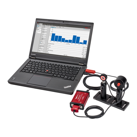
Optical power monitor
Hide thumbs Also See for PM101 Series:

Advertisement

Quick Links

Optical Power Monitor
Operation Manual
2023

Advertisement

loading
Need help?

Need help?

Do you have a question about the PM101 Series and is the answer not in the manual?

Questions and answers

Summary of Contents for THORLABS PM101 Series

  • Page 1 Optical Power Monitor Operation Manual 2023...
  • Page 2 Version: Date: 07-Jun-2023 Copyright © 2023 Thorlabs...
  • Page 3 Contents Foreword 1 General Information 2 Requirements 3 First Steps 4 Graphical User Interface (GUI) 4.1 File 4.2 Devices 4.2.1 Active Devices 4.2.1.1 Add Devices 4.2.1.2 Edit Devices 4.2.2 Settings 4.2.3 Information 4.2.3.1 User Calibration of Sensors 4.2.3.2 Firmware Update Tool for Power Meters 4.2.4 Measurement 4.2.5...
  • Page 4 5.2.5 Custom Sensors 5.3 Single Photon Counting Device 6 Version Information 7 Instrument Driver for Thorlabs Power Meters 7.1 Power Meter Driver Switcher 7.2 Adaptation of Customer Software 8 Troubleshooting 9 Write Your Own Application 9.1 32 bit Operating System 9.2 64 bit Operating System...
  • Page 5 Paragraphs preceded by this symbol explain hazards that could damage the instrument and the connected equipment or may cause loss of data. Note This manual also contains "NOTES" and "HINTS" written in this form. Please read this advice carefully! © 2023 Thorlabs...
  • Page 6 To control complex setups, the OPM can monitor up to 8 Thorlabs sensors on Thorlabs power meters connected in parallel via USB or Bluetooth also on your tablet computer.
  • Page 7 1 General Information Meter Monitor or if you are using Custom Made Software, please read the Instrument Driver for Thorlabs Power Meters section to revert to the driver PM100D.dll. © 2023 Thorlabs...
  • Page 8 Free USB 2.0 Port, USB Cable According to the USB 2.0 Specification Software Requirements The OPM software is compatible with the following operating systems: ® · Windows 8.1 (32 bit, 64 bit) ® · Windows 10 (32 bit, 64 bit) ® · Windows 11 (64 bit) © 2023 Thorlabs...
  • Page 9 3 First Steps 3 First Steps The Optical Power Monitor can be downloaded from the Thorlabs website: https://www.thorlabs.com/software_pages/ViewSoftwarePage.cfm?Code=OPM Note Do not connect a power meter to the PC during software installation! Please make sure that the installation is carried out completely, including the reboot requests.
  • Page 10 PM100USB with a Thorlabs Photodiode Power Sensor S122C, or a Thorlabs PM101 with a Thorlabs Photodiode Power Sensor S120C, connected to a PC running ® with OS Windows 10. Variations in the interface due to certain power meter consoles are...
  • Page 11 4.1 File The File menu provides the following options: Load Files Generated in Monitoring Load Files Generated by the Thorlabs PM400 Print a Screen Shot Generate a Screen Shot to be Saved as an Image Note PM400 files : The file structure of data saved by the Optical Power Monitor and the PM400 differ.
  • Page 12 If no power meters are connected to the PC or automatically recognized, the OPM starts with the Found Devices panel instead of the Measurement panel. Use Found Devices to scan for devices and connect them to the software. The OPM automatically connects the first recognized power meter. © 2023 Thorlabs...
  • Page 13 "Active Devices" list. · Click in the Active Devices table to add devices. · Click Rescan if no devices are detected to find all devices connected to the PC or reconnect devices to the PC. © 2023 Thorlabs...
  • Page 14 The status is shown in the field Active Devices next to the device name. Attention Instrument Driver Be aware that different instrument drivers may be used by your device. The OPM recognizes and runs with power meters using the new driver TLPM or a legacy driver PM100D. However, when © 2023 Thorlabs...
  • Page 15 In case the legacy driver PM100D is used, the information panel under devices will show a field USB driver, indication NI-VISA™. In this case, please use the driver switcher , that is automatically installed with the OPM to change to the new driver TLPM. © 2023 Thorlabs...
  • Page 16 Device: Adjust Device Settings Beam Parameters: Adjust Light Source Settings Display Parameter: Select the parameter that should be displayed as the main parameter in all 4 measurement monitors: Measurement, Tuning, Statistics, and Graph. Resolution: Set the desired measurement resolution. © 2023 Thorlabs...
  • Page 17 Bandwidth: Set the bandwidth of the photodiode to low or high, depending on the incoming signal and the properties of your photodiode sensor (please see the specification of your sensor and the Thorlabs Photodiode Tutorial).
  • Page 18 Power Meter Driver Switcher 4.2.3.1 User Calibration of Sensors The OPM provides a Calibration Wizard for the user to calibrate Thorlabs Photodiode and Thermopile Sensors in combination with a power meter. In principle, the Calibration Wizard uses a measured single point signal from a trusted reference sensor to calibrate the sensor connected to the power meter.
  • Page 19 The wizard leads the customer through the protocol. The start screen allows to choose between the factory calibration and a user calibration. Click "Perform User Calibration" to start a calibration or select and apply a previously saved calibration. © 2023 Thorlabs...
  • Page 20 To start a new calibration, define the user and click NEXT to adjust the background noise "Zero Adjust". Follow the instructions and click "START". The background is measured. This can be repeated. When the background measurement is finished, click "NEXT" to proceed to the calibration. © 2023 Thorlabs...
  • Page 21 When the calibration is done the following screen appears. To ensure that the calibration is within a reasonable range, the calibration is limited to values differing less that 20% from the reference values. An error message appears if the sensor that is calibrated is out of range. © 2023 Thorlabs...
  • Page 22 Click "NEXT" to write the calibration data in the internal memory of the power meter and save the results as a .pdf file on the PC. To take a second measurement at, for example, a different wavelength, click "Add Entry". © 2023 Thorlabs...
  • Page 23 Either have the OPM search the web for the latest firmware or download the firmware for your power meter from the Thorlabs software website. In case you download the firmware to your PC, choose the desired file and click "Next".
  • Page 24 In the measurement panel, the currently measured numerical values of selected parameters are displayed. Use the Tool Bar to add more parameters to the display, maximize the display screen, or reset the measurement. The display resets when a different device is selected. © 2023 Thorlabs...
  • Page 25 Reset min/max: Click the icon to reset the displayed minimum and maximum values and recalculate their ratio. Maximize the Screen: Switch to full screen mode. Only the main parameter and wavelength will be displayed. © 2023 Thorlabs...
  • Page 26 Shrink: Reduce size of the display to view all selected parameters. 4.2.5 Tuning This panel shows the analog needle simulation of the currently measured value along with the digital numerical value. © 2023 Thorlabs...
  • Page 27 The display can be adjusted using the Tool Bar. Enable/Disable Delta Mode The Delta Mode shows the fluctuation around the measured value at the moment of starting the delta mode. This value is reset to zero by clicking © 2023 Thorlabs...
  • Page 28 View the Delta Mode in % by selecting the tick-box: Delta Mode (% ) in the lower right display, marked red. Zoom in/out: The zoom-factor is determined by the current Min and Max-values. Reset min/max: Reset the displayed zero-, minimum and maximum values and recalculate their ratio. © 2023 Thorlabs...
  • Page 29 The number of data points used for statistics can be set as the duration of acquisition (Time) or number of data points (Sample). These settings are also applied in the Graph panel for the display of power meter signal over time. © 2023 Thorlabs...
  • Page 30 Highest Value Recorded During the Interval Used for the Statistics Calculation Mean: Mean Calculated Based on the Data Recorded During the Interval Set in Statistics/Graph Settings Standard Deviation: Standard Deviation Calculated Based on the Data Recorded During the Interval Set in Statistics/Graph Settings © 2023 Thorlabs...
  • Page 31 Zoom: To zoom into the chart, place the mouse cursor over the diagram and scroll. Tool Bar Settings: Set the displayed time interval of the measurement in time or sample number. These settings are also applied in the Statistics panel © 2023 Thorlabs...
  • Page 32 Most Recent Value: The value of the most recent data point collected in the time interval. Samples: Number of samples acquired for the time interval set in Statistics/Graph settings Time: Recording time acquired for the display of the time interval set in Statistics/Graph settings © 2023 Thorlabs...
  • Page 33 Select the devices and parameters to be monitored. Logging Settings and Select the settings for recording and saving of the measurement and Logging Information review settings in the panel Information. Start Logging. Logging Chart Select the displayed parameters. © 2023 Thorlabs...
  • Page 34 Logging Chart Add devices and parameters from the list of Deactivated Values to the Table Configuration. Remove Values by deselecting them in the left panel. Choose a custom name for the device in your setup. © 2023 Thorlabs...
  • Page 35 Configure the logging of a measurement and select the output file format, location and name and set the duration and resolution for logging in the Settings menu. Please read the section File Format to learn about the data saved in the log files. Review the Logging Settings prior to starting the measurement: © 2023 Thorlabs...
  • Page 36 Click this button to start logging of the measurement. If the file name was already used, a warning window appears. The Logging Settings panel will change to the Logging Information panel and show the status of the measurement. © 2023 Thorlabs...
  • Page 37 4 Graphical User Interface (GUI) © 2023 Thorlabs...
  • Page 38 To configure the chart display settings in the real-time measurement, choose any parameter and device (Displayed Devices) selected in the monitoring Table . Assign different colors to easily distinguish power meters and parameters in the display. Enable a second chart by moving the toggle switch in Chart 2 to Enabled. © 2023 Thorlabs...
  • Page 39 Data recorded in the Monitoring panel when choosing to save as single file only are also saved as .csv files. These data can be opened in the Data Viewer or in a text editor. 2) Large Data Volumes © 2023 Thorlabs...
  • Page 40 To load data into the Data Viewer, go to File and select Load to open the file of interest. The loaded data are displayed as a list of Devices, the Data Chart of data points over time and the Logging Information. © 2023 Thorlabs...
  • Page 41 Serial Number of the Sensor ® Wavelength Analyzed in the Optical Setup ® Second Device: Name as Set in Edit Device ® Go to the Data Chart and use the Tool Bar to configure the display of devices and parameters. © 2023 Thorlabs...
  • Page 42 The Data Chart displays the loaded data over time. The display optionally includes a legend for the monitored devices and a cursor to choose the display of a specific measurement value. Use the Tool Bar on top of the chart to edit the display and analyze the data set. © 2023 Thorlabs...
  • Page 43 Zoom Selection: Zoom into a ROI by selecting the area. The user can then move a window of the size of the ROI through the whole chart area. Zoom Selection: © 2023 Thorlabs...
  • Page 44 PM100D.dll to the newer TL.dll. While the PM100D.dll supports older software, generated with the older driver, the TL.dll supports all functions of all Thorlabs power meters. Visit the section Instrument Driver for Thorlabs Power Meters for more details.
  • Page 45 · NTC: With the PM102, the user can monitor the temperature with an attached NTC. For more information on this feature, please see the PM102x manual or the section Temperature Sensor TSP-TH on PM400, PM101, PM102, PM103, PM5020 © 2023 Thorlabs...
  • Page 46 PM102x manual for more details PM102x with Thermal Position Sensors S44xC All PM102x power meters are compatible with Thorlabs Thermal Position Sensors. When connected to a S44xC sensor, the OPM shows the interfaces described in the section Thermal Position Sensors in the chapter "Sensor Dependent Functions".
  • Page 47 In this setting, the display shows the default recorded signal as provided by the power meter. PEAK If a signal exceeds the set trigger threshold, as set on the PM5020, the peak value occurring after the trigger is displayed. © 2023 Thorlabs...
  • Page 48 Time base: Sets the time for 10.000 samples. o Horizontal Pos.: This allows to set the point in a periodically recurring signal event when to start the trigger. The vertical line can be moved along the horizontal axis. © 2023 Thorlabs...
  • Page 49 Find below the relevant changes in the OPM when using a pyroelectric energy sensor, described for a setup using a ES111C pyroelectric sensor connected to a PM400 power meter. The interface looks the following way: © 2023 Thorlabs...
  • Page 50 1-3 calculated from signal pulses 1-4. Since this is a rolling average, the second average power value is calculated using signal pulse 2 to 5 and so on. © 2023 Thorlabs...
  • Page 51 4. Monitoring Menu Table configuration For pyroelectric sensors, the Table Configuration now additionally lists the parameters Energy, Fluence and Average Power that can to be logged in the experiment and continuously displayed. © 2023 Thorlabs...
  • Page 52 For pulse intervals shorter than the saving interval, the displayed value is the last value sent by the power meter. For higher resolution measurements, please use the Graph mode. © 2023 Thorlabs...
  • Page 53 5.2.2 Temperature Sensor TSP-TH on PM400, PM101, PM102, PM103, PM5020 For PM400, PM101, PM102, PM103, and PM5020 the temperature can be recorded by the Optical Power Monitor if one or, for PM5020, two Thorlabs Temperature Sensors TSP-TH alternative NTCs are attached. Please see the PM400 Manual...
  • Page 54 When the sensor's natural response characteristic function is known, the final power reading can be modeled and predicted well before the sensor reading has stabilized. Thorlabs' power meter consoles calculate and display predictions of the stabilized power reading when Thorlabs sensors with sensor time constants larger or equal to 0.5 s (natural response time larger than 1s) are...
  • Page 55 Find below the relevant changes in the OPM when using a Thermal Position Sensor, described for a setup using a S440C thermal position sensor connected to a PM102 power meter. The Thorlabs Thermal Position Sensors S44xC can be run using the PM400, PM102, PM102A, or PM102U and the OPM interface will appear correspondingly.
  • Page 56 Optical Power Monitor When a Thorlabs Thermal Position Sensor is connected to a power meter and run via the OPM, the OPM menu for "Devices" gives the option to display either the power signal or the positional signal. When the "Power" is chosen in the section "Parameter", the OPM shows the standard interface.
  • Page 57 5 Optical Power Monitor with different Devices 2. Devices - Measurement Menu The Measurement interface displays the X and Y - position values and other values selected via the icon. Options are shown below. © 2023 Thorlabs...
  • Page 58 The interface "Tuning" shows a graphic display of the beam position in a target. Use the icon zoom into the target. Use the button to trace the position over time and the icon to refresh the trace. © 2023 Thorlabs...
  • Page 59 5 Optical Power Monitor with different Devices 4. Devices - Statistics Menu The interface "Statistics" shows the signal density on a particular position. © 2023 Thorlabs...
  • Page 60 5. Devices - Graph Menu The interface "Graph" shows the signal position over time as a two-dimensional plot for the X and Y position. The user can now change setting and zoom into the plot as for other graph displays. © 2023 Thorlabs...
  • Page 61 In addition to Thorlabs sensors, custom sensors can be used with the Optical Power Monitor. Note Please be aware that an adapter needs to be used to connect a custom sensor to a Thorlabs power meter. An adapter is not provided by Thorlabs. To build the adapter, please refer to the instructions in the manual of the respective power meter.
  • Page 62 Optical Power Monitor The custom sensor type can be changed under Settings in the Active Devices panel to either "Photodiode Adapter", "Thermopile Adapter", "Pyro Adapter", or "Four Quadrant" sensor for thermal position sensors. © 2023 Thorlabs...
  • Page 63 After connecting of the SPCNT counting device to the PC running the installed OPM software, open the software and select the SPCNT as the active device in the left panel. The OPM software will then show the following interface. This chapter describe the functions for the SPCNT in the OPM software. © 2023 Thorlabs...
  • Page 64 Display - Parameter: Select between display of Frequency or Counts in the main panel Measurement. b. Device: i. Measurement Mode: Choose between Internal Binning to set the binning from within the OPM software, or Gated to use a TTL start/stop signal from an external device to define the binning. © 2023 Thorlabs...
  • Page 65 Internal Binning With Dead Time Gated In Gated mode, an external device provides an Active High TTL Signal to define the binning. The OPM software in Gated mode provides adjustment via the following interface with the parameters described below: © 2023 Thorlabs...
  • Page 66 Threshold [%] defines the signal level above which signal is counted. This function can be used to eliminate afterpulsing. The default settings for the threshold are optimal for the Thorlabs SPDMA and SPDMHx single photon detectors. To compensate for afterpulsing in other detectors, first determine the afterpulsing characteristics of the connected single photon detector and then set the threshold level.
  • Page 67 5 Optical Power Monitor with different Devices As in other applications of the Optical Power Monitor software, click the icon to add display of more features. © 2023 Thorlabs...
  • Page 68 Optical Power Monitor 6 Version Information For information on the software version, please go to the Help menu. © 2023 Thorlabs...
  • Page 69 Be aware that the driver assignment of the power meters is changed upon installation of the OPM. If you created your own software for remote operation of Thorlabs power meters based on the PM100D.dll driver, the software needs to be modified to use the new TLPM.dll driver. Please read...
  • Page 70 Use the PM100D.dll for the Power Meter Monitor, Optical Power Meter Utility, or Multi Power Meter software. The OPM can operate with either driver. However, some functions of PM101x, PM102x, PM103x, and PM400 will not appear when using the PM100D.dll. © 2023 Thorlabs...
  • Page 71 7 Instrument Driver for Thorlabs Power Meters The Help panel guides you to the Thorlabs website, the license agreement, and the software version number. Close the Power Meter Driver Switcher after the driver exchange to prevent unintentional use. Note You can use the different drivers for different devices in parallel. Example: Power Meter PM100USB SerialNumber 1 and Power Meter PM100USB SerialNumber 2 are both connected to the PC.
  • Page 72 The driver assignment of the power meters is changed upon installation of the OPM. If you created your own software for remote operation of Thorlabs power meters based on the PM100D.dll driver, the software needs to be modified to use the new TLPM.dll driver.
  • Page 73 · I can not use the software Power Meter Monitor Ø Reason: The Thorlabs Optical Power Monitor (OPM) uses a different driver for the connected power meters than the Thorlabs Power Meter Monitor. The instrument driver of the power meters was changed to the new driver upon installation of the Optical Power Monitor.
  • Page 74 Instrument Driver for Thorlabs Power Meters · I can not use my Custom Made Software to steer Thorlabs power meters anymore Ø Reason: The Thorlabs Optical Power Monitor (OPM) uses a different driver for the connected power meters than former Thorlabs power meter software applications. The instrument driver of the power meters was changed to the new driver upon installation of the Optical Power Monitor.
  • Page 75 In other words, the 32 bit VXIpnp driver works with both 32 and 64 bit operating systems, while the 64 bit driver requires a 64 bit operating system. Note The Thorlabs Optical Power Meter software and drivers contains 32 bit and 64 bit applications. In 32 bit systems, only the 32 bit components are installed to C:\Program Files\...
  • Page 76 In case LabVIEW™ is not installed or if LabVIEW™ versions 2017 and higher are installed, the LabVIEW™ driver will be installed in: C:\Program Files\Thorlabs\PowerMeters\LabVIEW\LabVIEW 32bit\TLPM\TLPM.llb .net wrapper dll C:\Program Files\Microsoft.NET\Primary Interop Assemblies… …\ Thorlabs.TLPM_32.Interop.dll C:\Program Files\IVI Foundation\VISA\VisaCom\… …\Primary Interop Assemblies\ Thorlabs.TLPM_32.Interop.dll Python wrapper C:\Program Files (x86)\IVI Foundation\VISA\WinNT\TLPM\Example\Python\TLPM.py © 2023 Thorlabs...
  • Page 77 32 bit files - to “C:\Program Files (x86)” Below are listed both installation locations, so far applicable. VXIpnp Instrument Driver: C:\Program Files (x86)\IVI Foundation\VISA\WinNT\Bin\TLPM_32.dll C:\Program Files\IVI Foundation\VISA\Win64\Bin\TLPM_64.dll Note This instrument driver is required for all development environments! © 2023 Thorlabs...
  • Page 78 LabVIEW™ driver will be installed in: C:\Program Files\Thorlabs\PowerMeters\LabVIEW\LabVIEW 64bit\TLPM\TLPM.llb .net wrapper dll C:\Program Files (x86)\Microsoft.NET\Primary Interop Assemblies… …\ Thorlabs.TLPM_32.Interop.dll C:\Program Files (x86)\IVI Foundation\VISA\VisaCom\… …\Primary Interop Assemblies\ Thorlabs.TLPM_32.Interop.dll C:\Program Files\IVI Foundation\VISA\VisaCom64\… …\Primary Interop Assemblies\ Thorlabs.TLPM_64.Interop.dll Python wrapper C:\Program Files (x86)\IVI Foundation\VISA\WinNT\TLPM\Example\Python\TLPM.py Example for C Source file: C:\Program Files (x86)\IVI Foundation\VISA\WinNT\TLPM\Example\C\…...
  • Page 79 Thorlabs.TLPM.Interop.Sample.csproj Example for LabVIEWä C:\Program Files (x86)\National Instruments\LabVIEW xxxx\Instr.lib\TLPM… …\TLPM.llb (LabVIEWä container file with driver vi's and an example. "LabVIEW xxxx" stands for actual LabVIEWä installation folder.) Example for Python Solution file: C:\Program Files (x86)\IVI Foundation\VISA\WinNT\TLPM\Example… …\Python\PowermeterSample.py © 2023 Thorlabs...
  • Page 80 Further claims will not be consented to and will not be acknowledged. Thorlabs does explicitly not warrant the usability or the economical use for certain cases of application.
  • Page 81 Thorlabs, Inc. Thorlabs Ltd. sales@thorlabs.com sales.uk@thorlabs.com techsupport@thorlabs.com techsupport.uk@thorlabs.com Europe Scandinavia Thorlabs GmbH Thorlabs Sweden AB europe@thorlabs.com scandinavia@thorlabs.com France Brazil Thorlabs SAS Thorlabs Vendas de Fotônicos Ltda. sales.fr@thorlabs.com brasil@thorlabs.com Japan China Thorlabs Japan, Inc. Thorlabs China sales@thorlabs.jp chinasales@thorlabs.com © 2023 Thorlabs...
  • Page 82 www.thorlabs.com...