Table of Contents
Advertisement
Quick Links
Advertisement
Table of Contents

Related Manuals for THORLABS PM102


Summary of Contents for THORLABS PM102
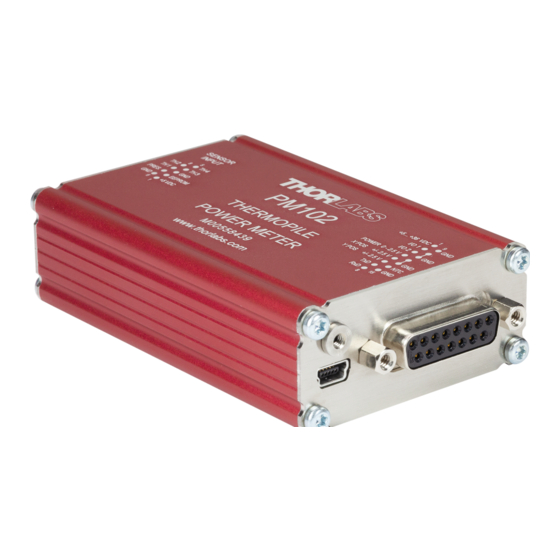
- Page 1 Optical Power Meter Interfaces PM102, PM102A, PM102U Operation Manual 2019...
- Page 2 Version: Date: 11-Dec-2019 Copyright © 2019 Thorlabs...
-
Page 3: Table Of Contents
3.2.15 Power Supply 3.3 Software 3.3.1 Software Requirements 3.3.2 PM102x Specific Software Functions 3.3.2.1 PM102 Specific Software Functions 3.3.2.2 PM102A Specific Software Functions 3.4 Maintenance and Service 4 Appendix 4.1 Technical Data 4.2 Pin Assignment Output Connector 4.3 Pin Assignment of the Sensor Connector... - Page 4 4.5 Return of Devices 4.6 Manufacturers Address 4.7 Certifications and Compliances 4.8 Warranty 4.9 Copyright and Exclusion of Reliability 4.10 Thorlabs Worldwide Contacts and WEEE Policy...
- Page 5 Paragraphs preceded by this symbol explain hazards that could damage the instrument and the connected equipment or may cause loss of data. Note This manual also contains "NOTES" and "HINTS" written in this form. Please read this advice carefully! © 2019 Thorlabs...
-
Page 6: General Information
USB port. The PM102 can alternatively use the DA-15 interface for instrument con- trol and to connect a power supply. Further, the PM102 can even be controlled via an external micro-controller, supplied by the customer. For more information on the special features of the... -
Page 7: Pm102X Model Comparison
Analog Output Operation Ö Ö Autonomous Operation to Ö Ö Analog Output Sensitivity Configurable Ö Ö Analog Output UART Operation Ö 2 Auxiliary I/O ports Ö NTC Input Ö Power Supply +5V to +36V Ö Table 1 © 2019 Thorlabs... -
Page 8: Ordering Codes And Accessories
To run the PM102x power meter, additional cables or mounting devices may be required. Cables · PM102: Cable to attach to the provided DA-15 connector housing. · PM102A: SMA cable: Please provide a cable with a SMA connector to operate the PM102A. -
Page 9: Requirements
PM102: Please provide an appropriate cable to be attached to the DA-15 connector. PM102A: Please provide appropriate cables to connect to the SMA ports. Software Requirements All models of the PM102x can be run with the Thorlabs' OPM software. Please see the require- ments for the OPM on the website. Sensor Requirements Thorlabs C-Series Sensors The PM102x supports all Thorlabs C-Series thermal power and position sensors. -
Page 10: Getting Started
Verify that you have received the following items within the package: 2.1 Parts List 1. PM102x Optical Power Meter Interface 2. USB Cable, Type A to Mini B, with Locking Screw, 1.5 m 3. PM102: DA-15 Connector and Connector Housing 4. Quick Reference 5. Certificate of Calibration © 2019 Thorlabs... -
Page 11: Operating Instructions
· Connect the PM102x to a PC or other power source via the USB port. o The PM102 accepts external power supplies with 5 V to 36 V via the DA-15 interface. When connecting the USB port while using an external power supply via the DA-15 port, connecting the USB port will automatically switch to the 5 V power supply via USB. - Page 12 Older Thorlabs Sensors without a DE-9 connector The PM102x will NOT automatically recognize sensors lacking a DE-9 connector, as for the case of the 'A' and 'B' series. Please contact Thorlabs for an upgrade of old sensors with DE-9 connectors.
-
Page 13: Power Meter Interface Features
, described in the following chapters. 3.2.1 PM102x Sensor Connector All models of the PM102x have the same connector shown here to the left side. The Pin as- signment is engraved on the front of the PM102x. © 2019 Thorlabs... -
Page 14: Pm102
The PM102 features a number of additional options, due to the DA-15 output connector. The PM102 is per default configured to RS232 configuration (+/- 5 V voltage level). This can be changed to a UART configuration (0/5 V voltage level) so that the PM102 can be accessed by external micro-controllers for instrument control and data export. -
Page 15: Pm102A
2. Three Analog Output Ports: POWER for the sensor signal, X POS and Y POS for the posi- tion of the signal in X and Y on thermal position sensors. Configurable Analog Output 4. Power Meter Control and Output via USB © 2019 Thorlabs... -
Page 16: Pm102U
PM102x 3.2.4 PM102U PM102U Special Features · Power Meter Control and Output via USB © 2019 Thorlabs... -
Page 17: Usb Operation
Termination Character LF (x0A; \n). The termination character needs to be enabled. Note PM102: To operate the PM102 via RS232, RxD, TxD, and GND need to be wired from the DA-15 con- nector to a 9 Pin female connector to perform the connections. PM102 DA-15 Pin... -
Page 18: Uart Operation
PM102 control. In RS232 operation the PM102 uses voltage levels of +/-5 V, while in UART mode the voltage level is shifted to 0/5 V. The PM102 can also be adjusted to accommodate micro-controllers using 3.3 V. When switched to 3.3 V, UART operation is toler- ant for 5 V input signal. -
Page 19: Analog Output
POS). 3.2.14 NTC Input To monitor the temperature in a test environment, the PM102 has an NTC Input (DA-15 Pin 14) which allows connection of an NTC thermistor. The measurement range is 0.1 – 100 kW. The set range R0 and the bandwidth B for the NTC thermistor can be adjusted in the OPM software or through SCPI commands. -
Page 20: Power Supply
Please find the requirements for the PC intended to be used for operation of the PM102x on website. 3.3.2 PM102x Specific Software Functions When using a PM102 power meter interface, the latest version of the OPM software shows several power meter specific functions. To see details, please also visit the manual. -
Page 21: Pm102A Specific Software Functions
3 Operating Instructions 2. When a PM102 is connected, it is possible to configure the analog ports POWER, X POS , and Y POS. There are two configuration options for these three ports: One for the port POWER and one for the two ports X POS and Y POS to configure the position in X and Y. -
Page 22: Appendix
Up to 200/s Analog Output, Configurable Number of Analog Outputs Connector DA-15 Pin 4, 5, 6 Power (configurable in V/W), Power (configurable in V/W), Signal X-Position & Y-Position X-Position & Y-Position (configurable in V/µm) (configurable in V/µm) © 2019 Thorlabs... - Page 23 0.16 kg (0.35 lb) The PM102x features an amplifier after each Thermal Sensor Input port TH1, TH2, TH3, and TH4 (Pins 4, 5, 8, and 9). They vary the measurement range. All 4 amplifiers are always on the same range. © 2019 Thorlabs...
-
Page 24: Pin Assignment Output Connector
Note: The PM102 features an amplifier after each Thermal Sensor Input port TH1, TH2, TH3, and TH4 (Pins 4, 5, 8, and 9). All 4 amplifiers are always on the same range. -
Page 25: Safety
The PM102x must not be operated in explosion endangered environments! Only with written consent from Thorlabs may changes to single components be made or com- ponents not supplied by Thorlabs be used. - Page 26 Thorlabs GmbH. The correction of interference caused by such unau- thorized modification, substitution or attachment will be the responsibility of the user.
- Page 27 4 Appendix 4.7 Certifications and Compliances © 2019 Thorlabs...
- Page 28 Thorlabs warrants material and production of the PM102x for a period of 24 months starting with the date of shipment. During this warranty period Thorlabs will see to defaults by repair or by exchange if these are entitled to warranty.
- Page 29 Contact Thorlabs for more information. Waste treat- ment is your own responsibility. “End of life” units must be returned to Thorlabs or handed to a company specializing in waste recovery. Do not dispose of the unit in a litter bin or at a public waste disposal site.
- Page 30 www.thorlabs.com...
Need help?
Do you have a question about the PM102 and is the answer not in the manual?
Questions and answers